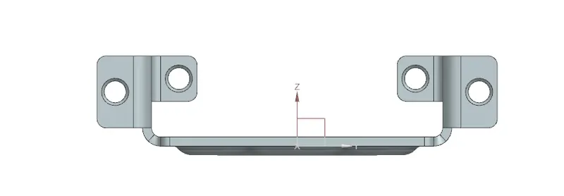
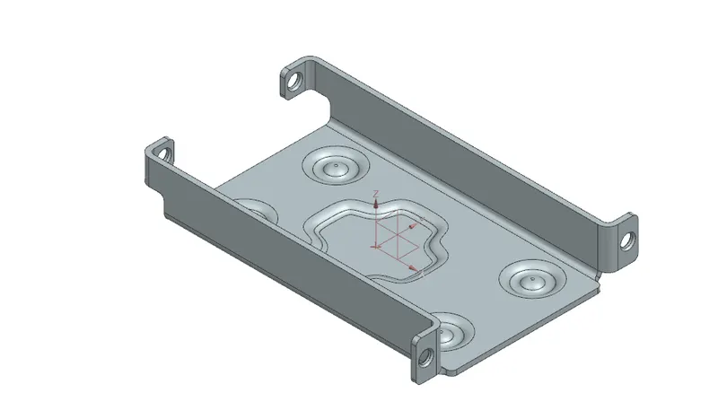
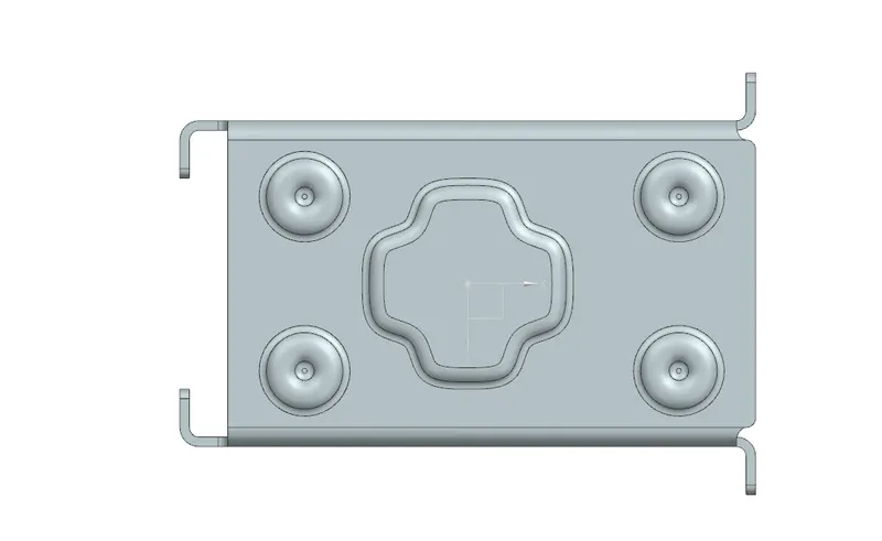
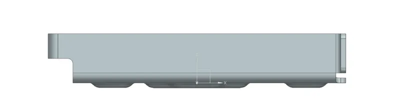
Advanced Sheet Metal Design Using NX Cad Challenge_1_Casing Design
OBJECTIVE:-
To design a sheet metal casting using NX Cad software with suitable commands to achieve the final product as per the inputs.
INTRODUCTION :
In Sheet metal Application we can create uniform thickness Sheetmetal parts using basic features Such as Tabs, flanges,s and jogs, we can also bend corners, cut out, bead, etc…features.
The Sheetmetal application provides an environment for the design of metal parts used in machinery, Automotive and Aerospace Enclosures, Brackets, and other parts that are normally manufactured with a brake press.
The complex sheet metal part can be designed in the Solid model work Bench and then we convert it to a Sheet metal part. We can also import, clean up and convert a non Sheet metal part into a valid Sheet metal part. Flat pattern Sheetmetal data can be used for the manufacturing process. The material parameters such as thickness, bend radii, and bend relief can be easily set as default settings.
DESIGN METHODOLOGY:
Design methodology can be explained by the following flow chart.
|
Start casing design |
|
Create a rectangular sketch of dimension 60X50 in XY plane(P) and a metal sheet of thickness mm was created using TAB |
|
A rectangular metal sheet of 5X40 was removed using a Normal Cut out. |
|
A horizontal line was drawn at a distance of 10mm from the upper left corner of the metal sheet and the metal sheet was bent at the line. |
|
Again horizontal line was drawn at a distance of 10mm from the lower-left corner of metal sheet and bending was done as the above |
|
Flanges of length 5mm were added at an angle of 90 degrees at the extreme position of bend portions using the feature flange |
|
Corners were broken at the flange extreme position of radius 1mmby using the feature Break Corner |
|
Faces were unbent to make 2D sheets by using the feature Unbend |
|
Holes were added in plane P on the extra portions of the flange by using the feature Hole |
|
The required sketch was drawn which is centered at (0,0,0) and of each half size of 5mm and by using the studio spline feature required shape was created and the dimple was created by using the feature Dimple |
|
4 Beads were created around the Dimple by using the feature Bead |
|
Rebend the bent portion by using the feature Rebend |
|
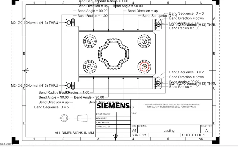
Drafting was using the feature Flat pattern |
|
end |
DESCRIPTION:
Using the tab option, the desired sketch was then created on to the base tab was created .later that desired sketch was then created on the surface of the tab to further cut a section out from the tab using the normal cutout option. the required surface was bent to make the perfect shape of the casing, after sketching the line was created and it should be bent to the angle of bend required.
Flanges are added by 'flange command' to the corner for the gripment of the previously bent surfaces. Break corner options are useful so that they make us view neatly and smoothly they help to radius the sharp corner.
unbend is done through unbend option will make the bent sheet metal unflap to the size and shape of the sheet to manageable requirement. the sketch is added to the surface to make the threaded holes on it using the hole option.
to add the dimple firstly we need to sketch the surface a shape using studio spline and later on the depth is added, and the sketch has to be rotated to the desired angle.
a single bead was added using a bead dialogue box, the bead was then mirrored multiple times using the mirror feature option. after having desired design the model was unbent using the command.
IMAGES:-