Advanced Sheet Metal Design Using NX Cad Challenge_1_Casing Design
CASING DESIGN
OBJECTIVE:- Casing Design using Sheet Metal features in NX CAD.
INTRODUCTION:- NX Sheet Metal provides a set of tools within the NX design environment that allows for simple and fast design of sheet metal parts, dependent on their material and manufacturing process, the most common of which is straight brake sheet metal forming.
DESIGN METHODOLOGY:- There are some step ot stages follows as shown as....
- Create a new sheet metal model as .prt file.
- Changing the parameters preferences accordingly.
- Create a sketch on certain plane.
- Use Tab tool for creating sheet metal of certain thickness.
- Use Normal cutout Tool for making a rectanglar hole in the sheet accoding to the sketch.
- Modify the model by bending material on one side of a sketch line by using Bend command.
- Add a flat flange at an angle to a planar face by using Flange command.
- Round or chamfer a sharp corner of a tab and flange face by using Bend Corner command.
- Flatten the bend and the material adjacent to the bend face by using Unbend command.
- Add a hole to one or more solid bodies in a part with counterbored, countersunk and threaded by using Hole command.
- Lift an area of the model inside the sketch that simulates the stamping tool by using Dimple command.
- Lift material along the contour of the sketch that simulates the stamping tool by using Bead command.
- Rebend command using to restores an unbend features to its previous bent state, along with any features addad after the unbend features.
- Drafting
Descrption:-
- Sketch:Creat a sketch in XY plane and draw a rectangle centred at the origin with an certain dimesions.
- Adding a Solid Sheet:Exit the sketch mode, use the tap button for creating first rectanglar metal sheet of 1mm.
- Cutout: In that sketch, draw a rectangle symmetrical with respect to the x-axis which is coincide with the left edge of the rectangular sheet of certain dimesions for making rectangular hole.
- Bending: Again draw a sketch in the plane consisting in two symmetrical horizontal lines w.r.t. the x-axis from the upper egde of the sheet. and Exit the sketch mode and click the bend button.
- Flange: Click the flange button, use a length of certain value and apply the flanges on the edge of the metal sheet as correponding symmetrical egde.
- Breaking Corner: click the break corner button and create the round corner on edges where required.
- Unbending the Face: click the unbend button, select as stationary face of the metal sheet for bending face one of its adjacent faces.
- Adding Holes: create a point on the center of hole. use the hole button.
- Adding Dimple
- Adding bead
- Use Mirror Feature for thier correspoding sketches.
- Rebending
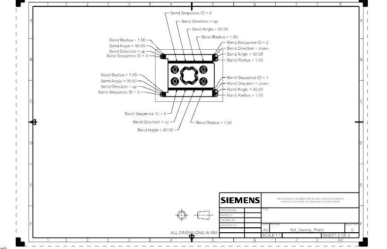
- Drafting: Click on flat pattern button for creating drafting file using base view features.
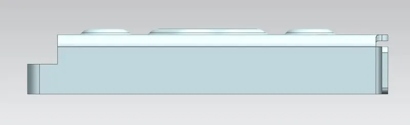
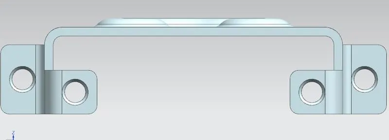
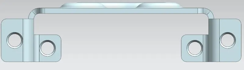
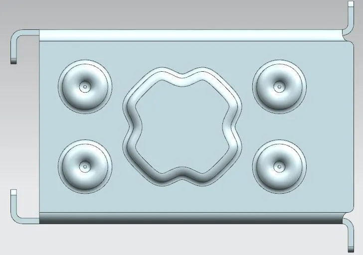
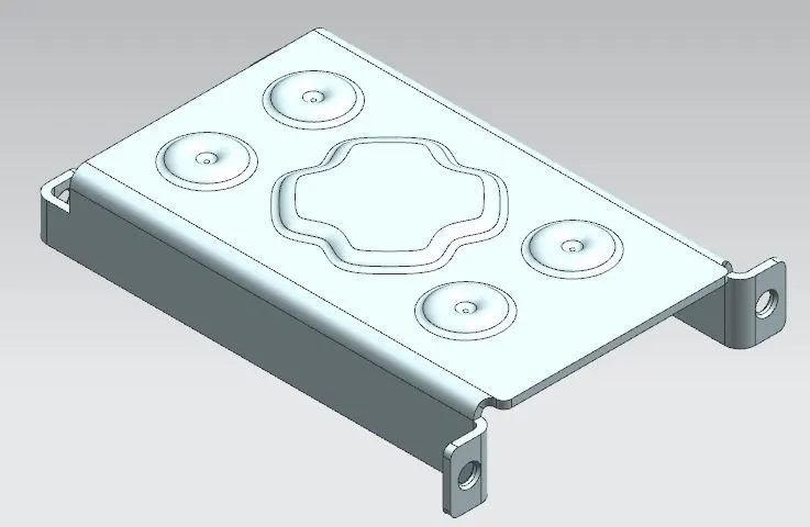
SCREENSHOT OF VIEWS of MODEL
- Front View
- Left View
- Right View
- Top View
- Isometric View
DETAIL DRWAING SHEET IMAGE OF MODEL
CONCLUSION:-NX sheet metal design software incorporates material and process information in sheet metalspecific modeling features: bends, flanges, tabs, cutouts, beads, dimples, louvers, corner and edge treatments, patterns and other formable features. You can also quickly convert solid models to sheet metal components, and create sheet metal parts that enclose other components.