Advanced Sheet Metal Design Using NX Cad Challenge_1_Casing Design
CASING
INTRODUCTION
A shell that protects or encloses something or an outer layer of metal, rubber etc that covers and protects something, such as a wire. It can be any shape like rectangle or circular shell.
OBJECTIVES
- Understanding user interference in NX SheetMetal.
- Draw the sketches with fully defined and Understanding and implementing features to complete the model in NX SheetMetal
- Application of relations to the entities.
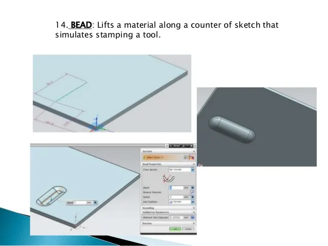
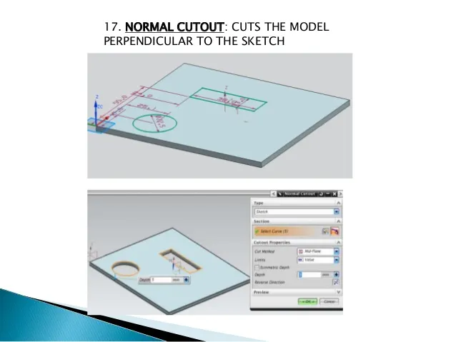
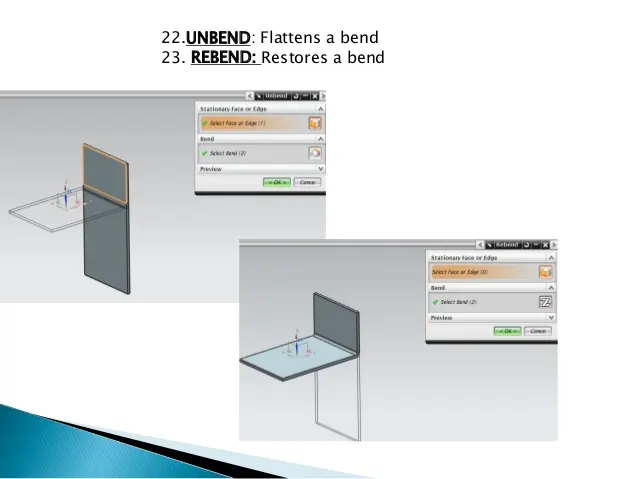
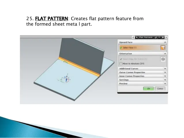
- Understanding the utility of NX SheetMetal tools like Tab, Flanges, Hole, Mirroring of sketch and features, Blend, Flat Pattern, Bend, Studio Spline, Bead, Dimple, Unbend, Rebend etc.
- Using the above tools to complete the casing with mechanical knowledge as well.
SHEETMETAL
Sheet metalis metal formed by an industrial process into thin, flat pieces. Sheet metal is one of the fundamental forms used in metalworking, and it can be cut and bent into a variety of shapes. Countless everyday objects are fabricated from sheet metal. Thicknesses can vary significantly; extremely thin sheets are considered foil or leaf, and pieces thicker than 6 mm (0.25 in) are considered plate steel or "structural steel".
Sheet metal is available in flat pieces or coiled strips. The coils are formed by running a continuous sheet of metal through a roll slitter.
In most of the world, sheet metal thickness is consistently specified in millimeters. In the US, the thickness of sheet metal is commonly specified by a traditional, non-linear measure known as its gauge. The larger the gauge number, the thinner the metal. Commonly used steel sheet metal ranges from 30 gauge to about 7 gauge. Gauge differs between ferrous (iron-based) metals and nonferrous metals such as aluminum or copper. Copper thickness, for example, is measured in ounces, representing the weight of copper contained in an area of one square foot. Parts manufactured from sheet metal must maintain a uniform thickness for ideal results.
There are many different metals that can be made into sheet metal, such as aluminium, brass, copper, steel, tin, nickel, and titanium. For decorative uses, some important sheet metals include silver, gold, and platinum (platinum sheet metal is also utilized as a catalyst).
Sheet metal is used in automobile and truck (lorry) bodies, airplane fuselages and wings, medical tables, roofs for buildings (architecture), and many other applications. Sheet metal of iron and other materials with high magnetic permeability, also known as laminated steel cores, has applications in transformers and electric machines. Historically, an important use of sheet metal was in plate armor worn by cavalry, and sheet metal continues to have many decorative uses, including in horse tack. Sheet metal workers are also known as "tin bashers" (or "tin knockers"), a name derived from the hammering of panel seams when installing tin roofs.
SHEETMETAL DESIGN
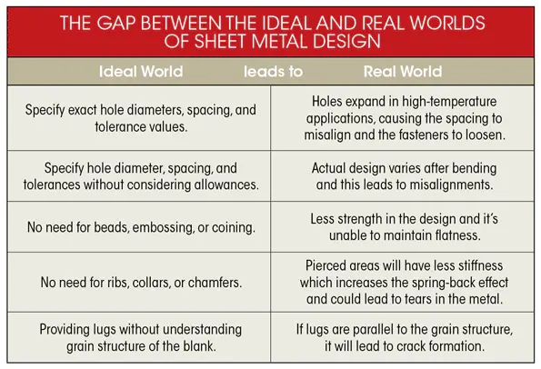
Engineers designing sheet-metal enclosures and assemblies often end up redesigning them so they can be manufactured. In fact, research suggests that manufacturers spend 30% to 50% of their time fixing errors and almost 24% of those errors are related to manufacturability. The reason behind these preventable engineering errors is usually the wide gap between how sheet-metal parts are designed in CAD systems and how they are actually fabricated on the shop floor. Many engineers developing 3D models for sheet-metal products are unaware of the fabrication tools used to form the part or product, and instead design models for an “ideal” world.
In the ideal world, everything is perfect. Tolerances and allowances are exact, and there’s no need to add any feature or change the design to accommodate the shop floor or real-world material behavior. But the truth is, numerous factors including chamfers at the edges, collars near hole, and spaces between drilled holes matter in the sheet metal world.
This gap between the ideal and real-world sheet-metal design usually proves costly. The overflowing engineering change orders (ECOs), fixing the design errors, and sending revisions back to the shop floor turns into a vicious cycle, one that is often difficult to break.
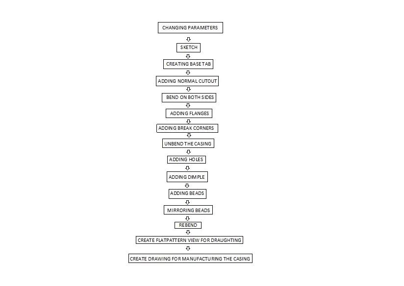
DESIGN PROCESS FLOWCHART FOR CASING
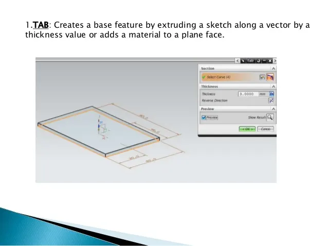
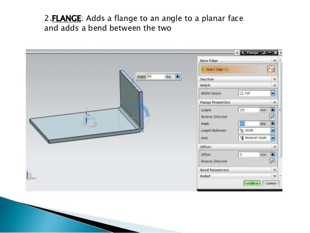
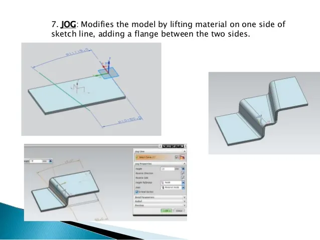
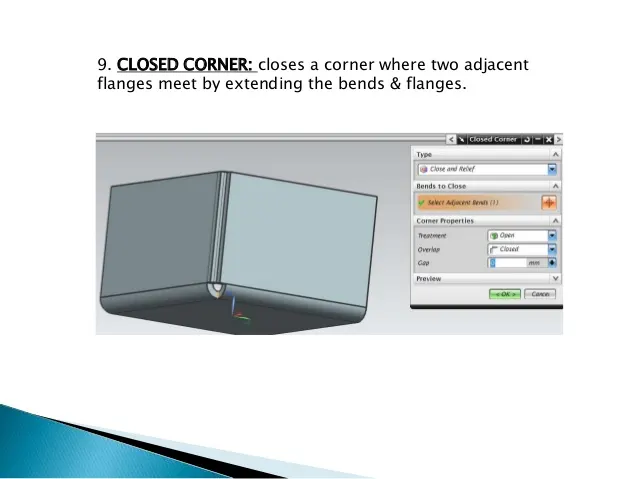
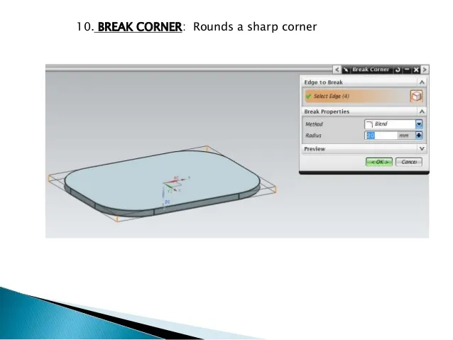
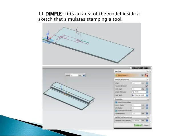
EXPLANATIONS OF TOOLS
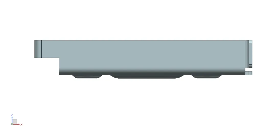
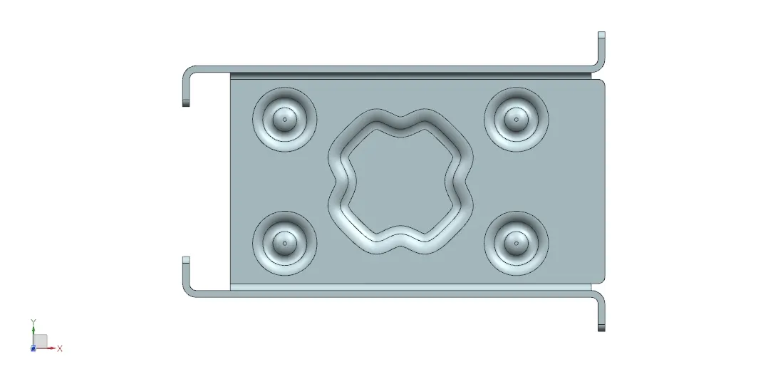
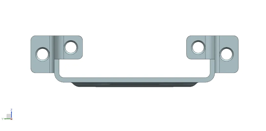
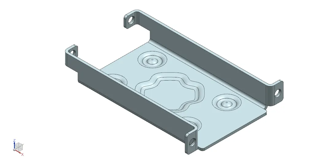
IMAGES OF CASING
FRONT VIEW
TOP VIEW
SIDE VIEW
ISO
ADDITION OF DRAUGHTING IMAGE
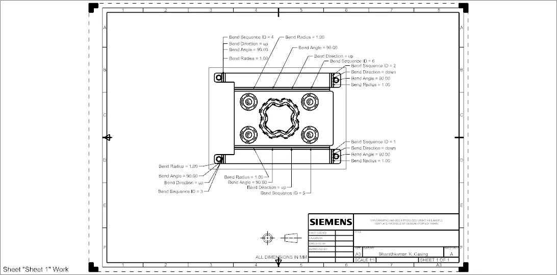
CONCLUSION
These are the tools, methods are used to design a casing using NX sheetmetal software. Thankyou