Advanced Sheet Metal Design Using NX Cad Challenge_1_Casing Design
Design of Casing using NX workbench
OBJECTIVE
The main objective of this project is to understand the various basic features of sheetmetal workbench in NX software by making use of them in order to build the casing.
INTRODUCTION
Sheet Metal Fabrication is the process of forming parts from a metal sheet by punching, cutting, stamping, and bending.
3D CAD files are converted into machine code, which controls a machine to precisely cut and form the sheets into the final part.
Sheet metal parts are known for their durability, which makes them great for end use applications. Parts used for low volume prototypes, and high volume production runs are most cost-effective due to large initial setup and material costs.
In this project a casing designed using different features present in Nx sheetmetal workbench. Casing is generally used to protect the component present inside this.
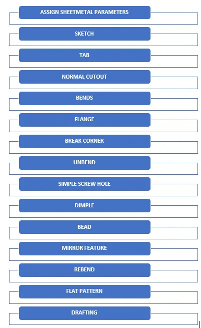
Design methodology for designing Casing
PROCEDURE
1. The first step in designing the sheetmetal is to assign the global parameters of the sheetmetal that needs to be created, in the global parameters material thickness, bend radius, relief depth and relief width is assigned. This input will remain constant throughout the designing of the sheetmetal features.
Steps to go to Sheet Metal Preference - Menu -> Preference -> Sheetmetal
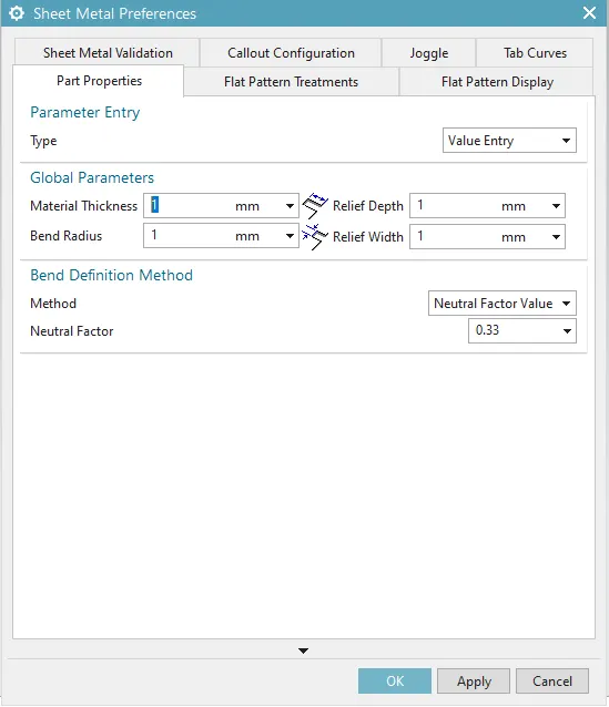
The above image shows the value assigned to the sheetmetal parameters that will be used to design the casing.
2. The next step in designing the component is to make the sketch for using the Tab feature.
Tab- This feature is used to give thickness to the required sketch which is drawn. It is the generally the first command which is used to make the base of the sheetmetal.
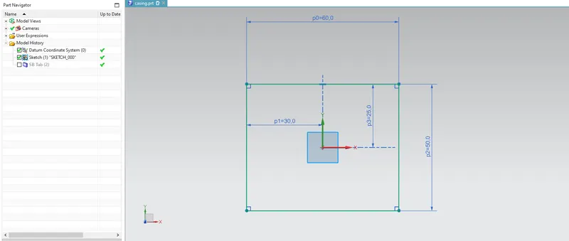
The above image shows the sketch used to make the base of the casing.
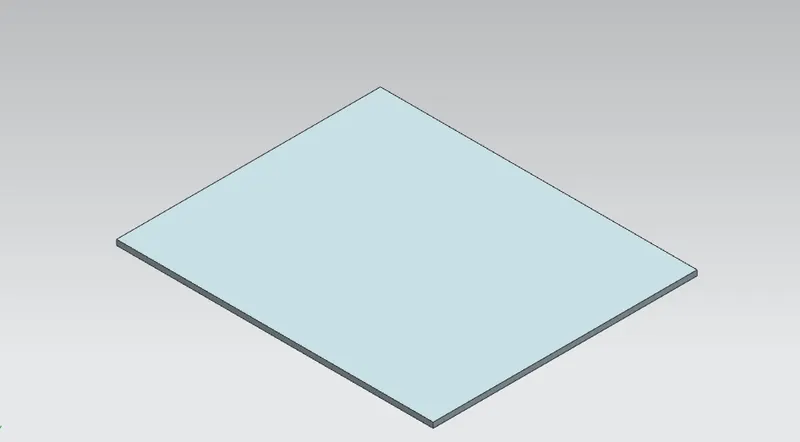
The tab created from the sketch is shown above with 1 mm thickness assigned in the global parameters earlier.
3. Normal cutout is the next feature used to give desired shape of the cutout that is needed.
Normal Cutout- This feature is used to remove the material from the sheetmetal material. A profile is first drawn using the sketch feature and the material will be removed inside the sketched profile.
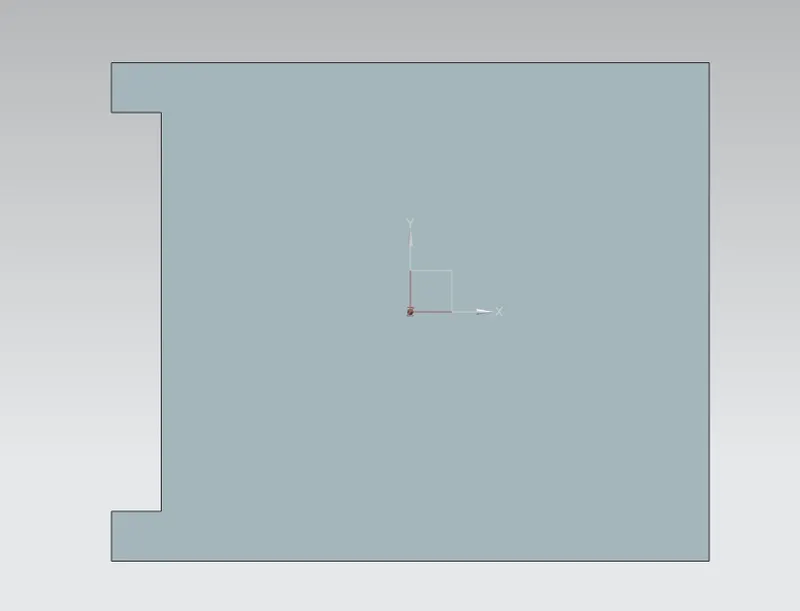
The above image shows that a profile was sketched in the left side of the material and then the required material was removed using the normal cutout feature.
4. The next step in designing the casing is to make bends near the ends of the above designed sheetmetal.
Bend- This feature is used to make bends in the sheetmetal along the sketched profile. The bends can be made throughout the material by making a small sketch by selecting Extend Section and also it can be only on the sketched profile by deselecting the extend Section.
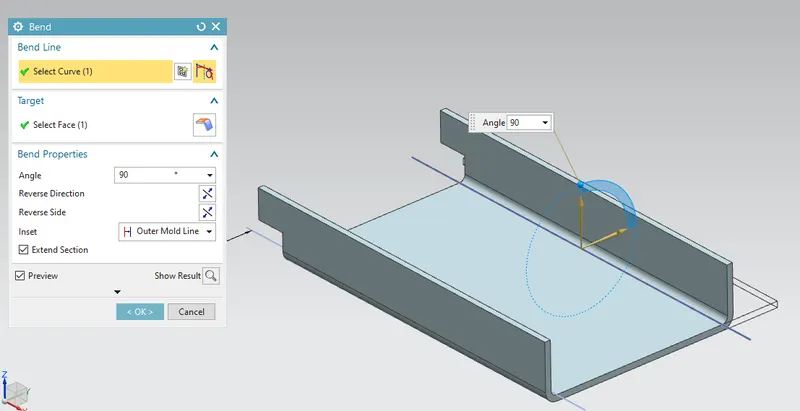
The above image shows the bends made by selecting the extend section so that the bend is made throughout the material horizontally near both the ends.
5. Flanges are made on some selected edges of the sheetmetal.
Flange- This feature is used to add a flat web at an angle to the planar surface. Flanges consists of web and bending radius which is already defined in the global parameters.
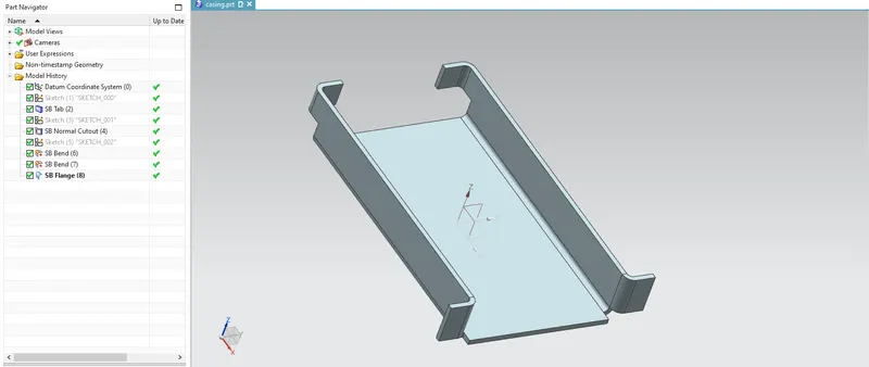
The above image shows the edges at which the flanges are made.
6. The most important characteristic of sheetmetal designing is that it should not have any sharp edges, in order to remove the sharp edges Break corner feature is used.
Break Corner - This feature is used to provide to convert the sharp edge into rounded edges.
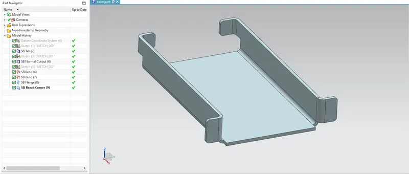
In the above image we can observe that the sharp edges are rounded at the required positions using the Break corner feature.
7. The next step in designing the casing is to unbend all the angled flanges.
Unbend - This feature is used to convert all the angled flanges into flat sheetmetal by selecting the base face along which all the other flanges need to be straightened.
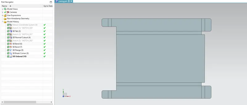
The above image shows that all the flanges that were created at an angle are unbened and then changed to straight surface using the unbend feature.
8. Holes are created at the required positions of the casing.
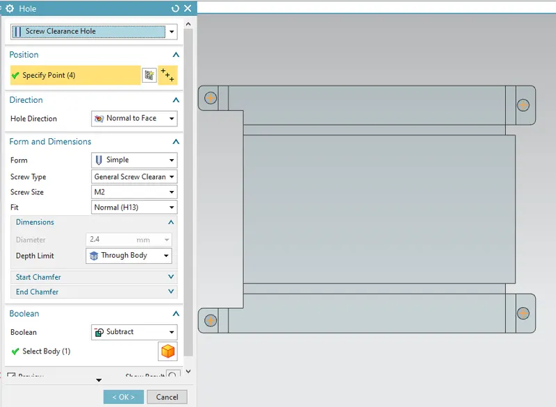
The above image shows that simple screw hole is seleced as form type with a size of M2 screws.
9. A sketch is drawn at the centre of the sheetmetal to form dimple on the sheetmetal.
Dimple - this feature is used to lift an area of the model by selecting a sketch with reference to which the area needs to be lifted. Dimple operation are done with the help of stamping tool in the manufacturing industry.
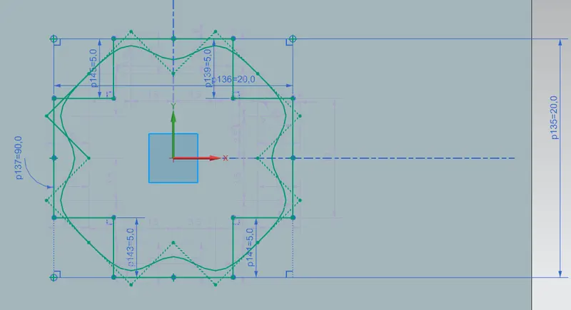
The above image shows the sketch which will be used to desing the dimple.
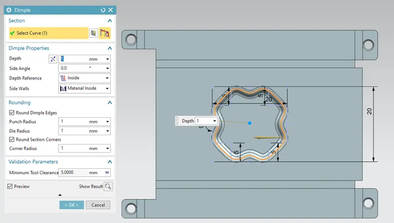
The above image shows the values of the depth, punch radius, die radius and the corner radius which is given to make the dimple.
10. Bead is the next feature which is used to make circular lifts at the required places. This operation is also performed with the help of stamping tool in the manufacturing industry.
Bead - this feature is used to lift material along the contour a sketch.
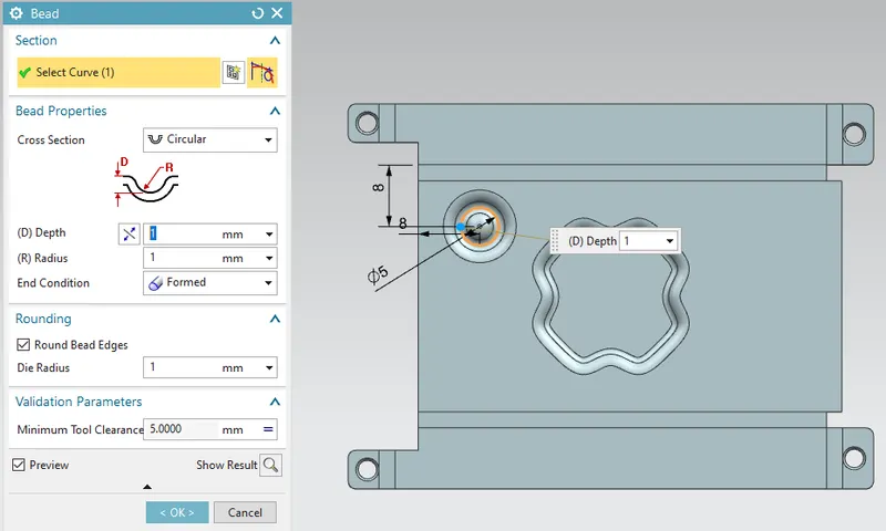
The above image shows the circular profile which is used to build the bead. Circular cross section was selected to give required shape to the bead. A 1 mm depth, radius and die radius was given as value with end condition as formed.
11. In order to create the same shape of the bead along the X and Y axis symmetrically mirror feature command is used.
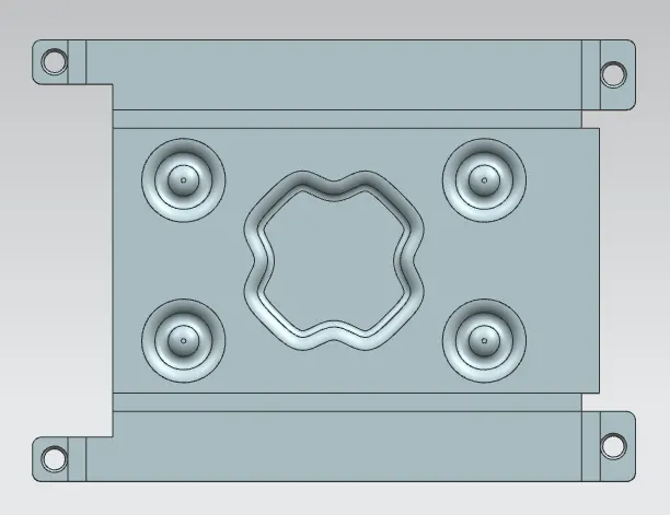
The above image shows the beads at required positions.
12. In order to bring the casing to its original shape along with bendings of the flanges rebend feature is used by selecting all the bending faces.
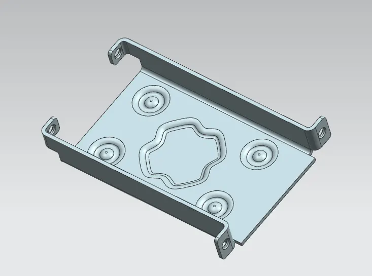
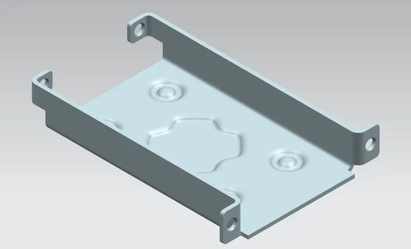
The above image shows the final casing which is designed using all the above features.
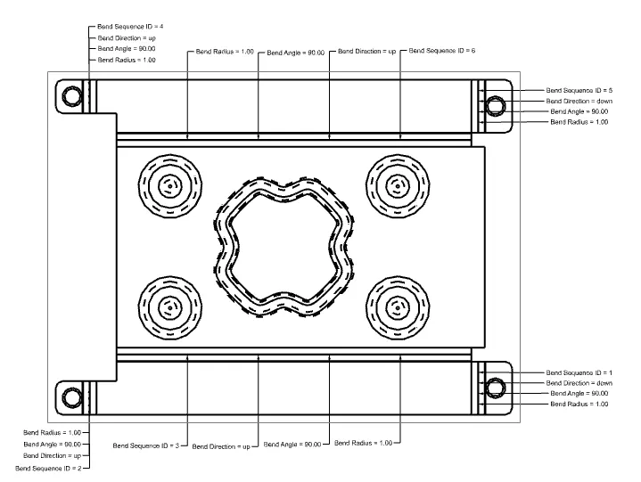
13. As the casing is fully designed, a 2D representation of the above model is made with the help of the Flat Pattern feature.
To view the flat pattern these steps need to be followed - In Part Navigation go to Model View -> Flat Pattern
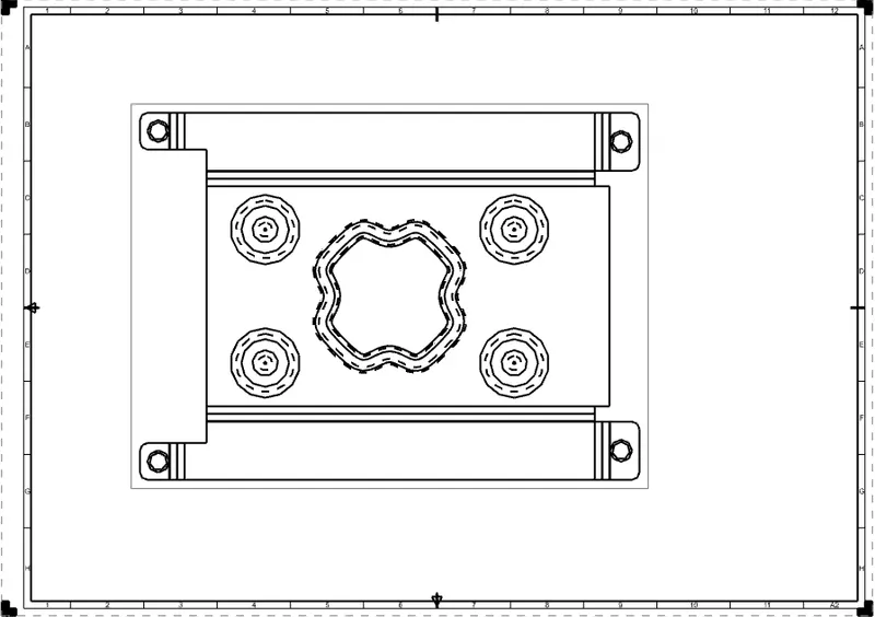
The above image shows the flat pattern view of the casing on the drafting sheet.
The different views of the casing model is shown below:
1. Top view
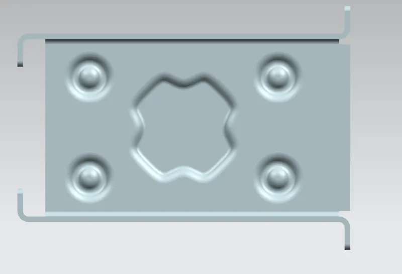
2. Front view
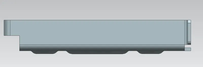
3. Side view
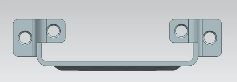
4. Isometric View
The detailed drawing of the casing is shown below:
CONCLUSION
1. The casing was successfully designed as per the requirements.
2. Flat pattern feature was used to show all the specifications of the casing that was modelled which is represented on the drawing sheet.