Adams Assignments – Problem 5 – Compliance
I opened the multilink suspension system.
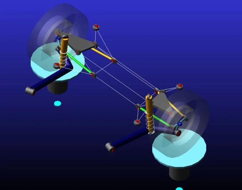
These parameters must be determine;
1-Brake Steer: Because of the braking force, wheels will create an Moment which causes to steer. Since the braking force is more in front wheel, the wheel will steer more than the rear wheel and this will cause an understeer or oversteer effect.
2-Traction Steer: Because of the traction force, wheels will create an Moment which causes to steer.
3-Longitudinal wheel center recession under traction: Wheel centre recession is a measure of the longitudinal motion of the wheel centre when the suspension travels into bump.
4-Longitudinal wheel center recession under braking: İt is the same as above but under braking condition.
5-Lateral force compliance steer: Because of the Lateral force, wheels will create an Moment which causes to steer.
6-Lateral force compliance camber: Because of the Lateral force, wheels will create an Moment which causes to tend the wheels.
7-Bumb Steer: During wheel travel, it is possible that the steering wheel rotates without any response from the driver because of the error that occurs in steering geometry.
Now let's start with the simulation. For the braking condition I give 4000 N braking Force as an input and runned the simulation.
1-Brake Steer
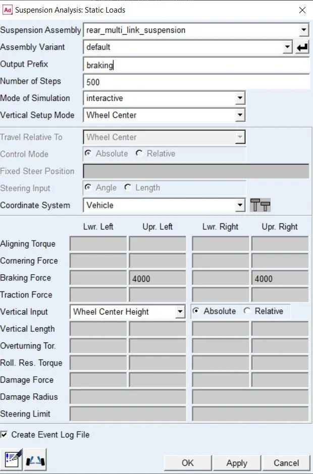
To determine the brake steer, the X data was chosen as wheel_base_travel and for the Y data it was chosen the toe angle (or steer angle since it the same in rear suspension system).
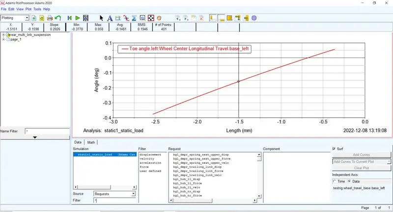
As it can be seen the Brake steer is euqal to 0.202 deg/mm=202 deg/m. The sign is pozitif that's it' toes out.
2-Traction Steer
For the Traciton steer same X and Y data were chosen but the simulationw as runned for the traction force condition.
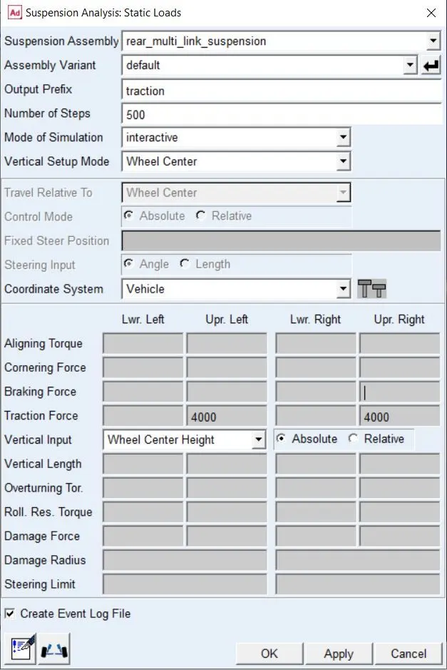
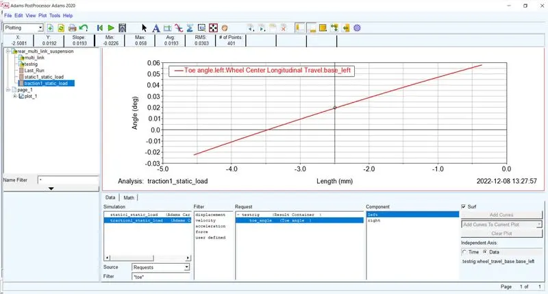
İt can be senn that the Traction Steer is equal to 19.3 deg/m. The sign is pozitif that's it' toes out.
3-Longitudinal wheel center recession under traction
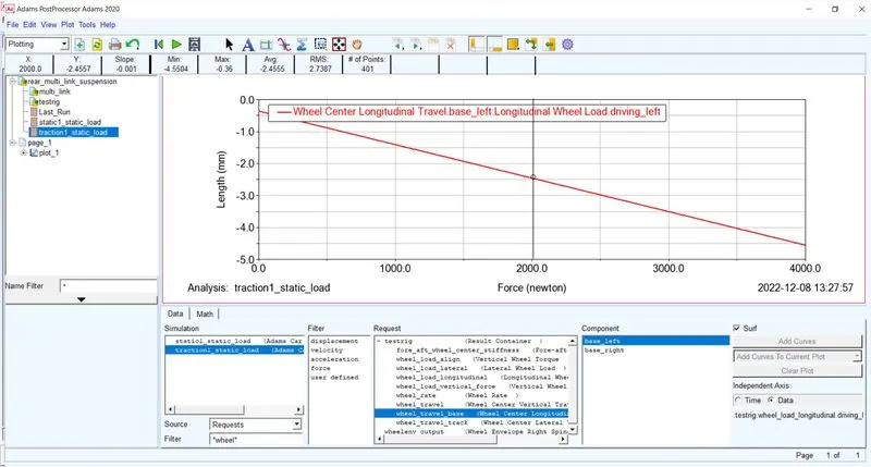
For the X data the Wheel_Travel_Long. for driven was chosse. This value must be very small since the Long. travel causes because of the Long. suspension compliance.
For the Y data wheel_travel_base was chosen.
The Longitudinal wheel center recession under traction is equal to 1 mm/KN.
4-Longitudinal wheel center recession under braking
The X data was chosen as wheel_travel_long for braking and Y data is the same as above.
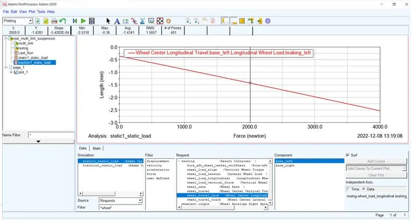
The Longitudinal wheel center recession under braking is equal to 0.542 mm/KN.
why the two are different ?
The reason why these two values are different is because the application of these forces applied on a different point. The traction fore is applied to the wheel center (because the drive shaft is connected to the wheel center) and the braking force is applied to the contatc patch.
5-Lateral force compliance steer
The simulation is runned again under cornering condition.
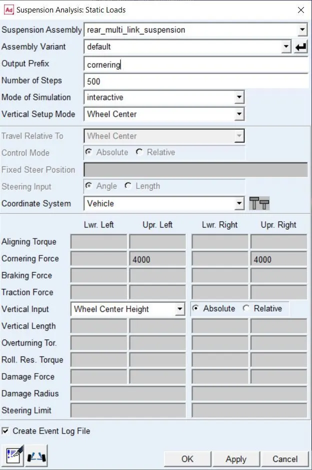
For the X data the wheel_load_lateral was chosen and for the Y axis steer angle (or toe angle) was chosen.
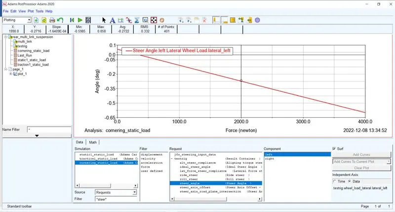
The Lateral force compliance steer is equal to 0.164 deg/KN and it will causes to toes out the wheel which produces oversteer.
6-Lateral force compliance camber
Same condition as above is performed but for the Y data the camber angle was chosen.
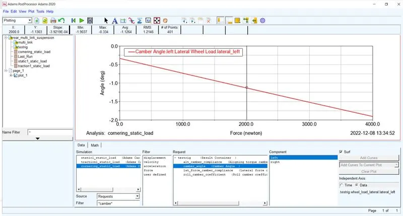
The Lateral force compliance camber is equal to 0.392 deg/KN and causes negative camber on wheel which causes understeer effect.
7-Bumb Steer
For the Bumb steer we will run a parallel wheel travel simulaiton.
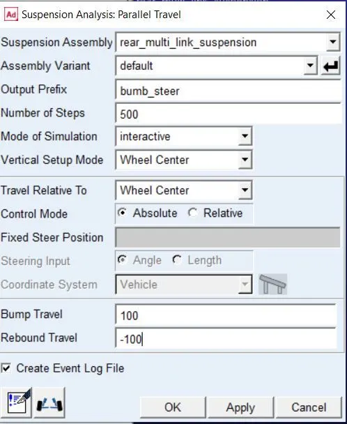
Then for the X data wheel travel was chosen and for the Y data toe angle (or steer angle).
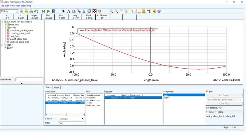
The Bumb steer is equal to -3.3 deg/m. İt will cause to toes out the wheel and it's increase the oversteer effect.
Optimize the hardpoints to achieve a bump steer of +2.6 deg/m
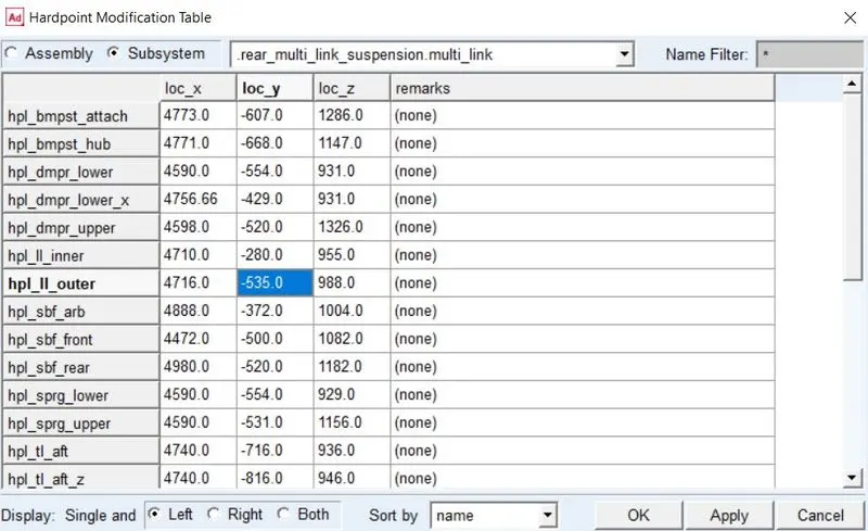
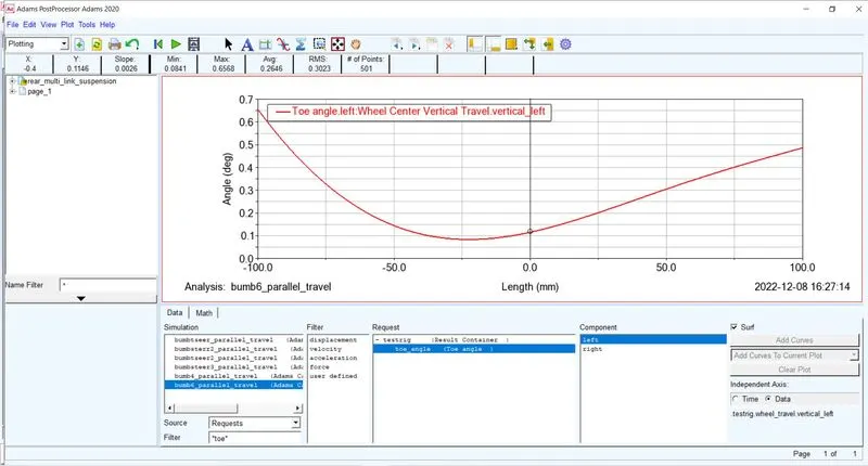
Bumb Steer is now +2.6 deg/m. As it can be seen the bumb steer value is now positive and that will makes the rear wheels toe in which causes understeer effect.
Optimizing Bushings to get Traction wheel center recession – stiffness of ~500 N/mm
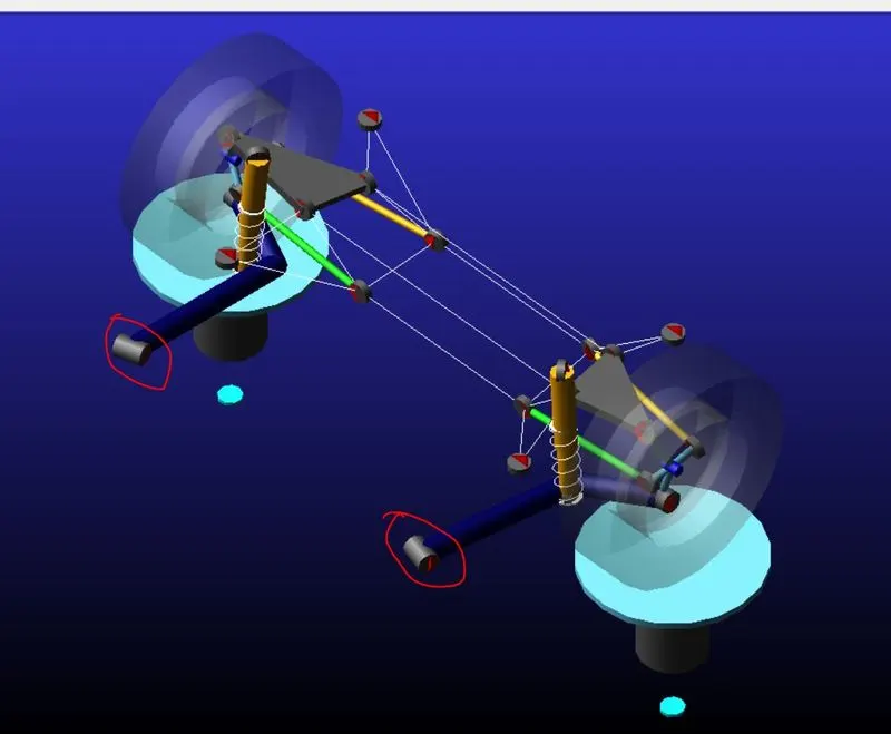
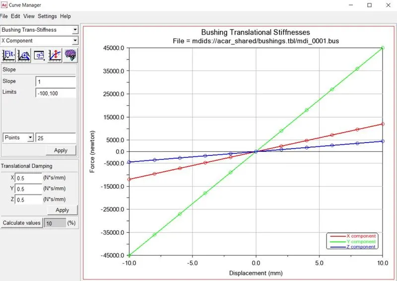
The wheel recession stiffness is depended on the moment arm. The largest moment arm in this suspension geometry has the trailing arm. That why we change the stiffness of hte trailim arm bushing to get our desired stiffness value.
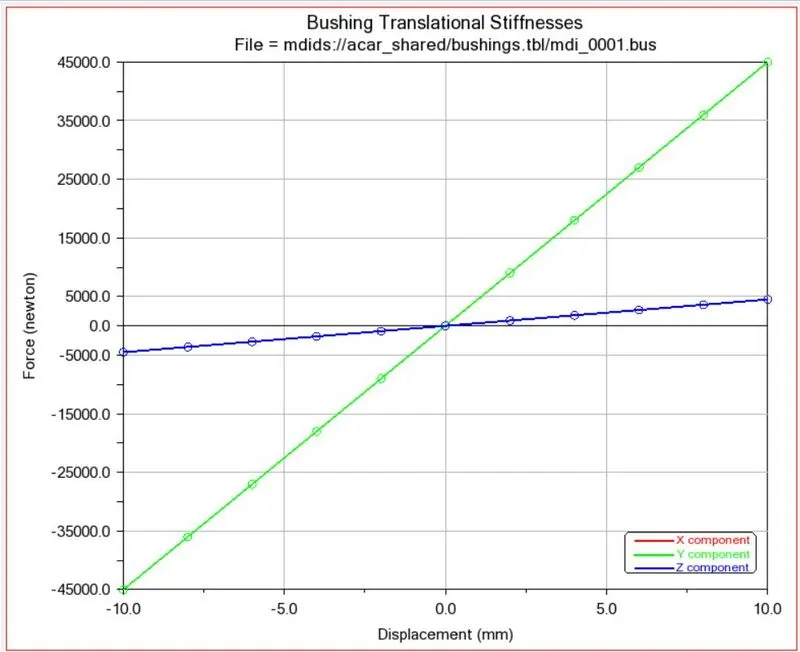
Orginal Bushing Stiffness Graph
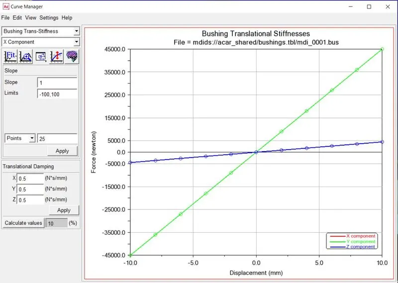
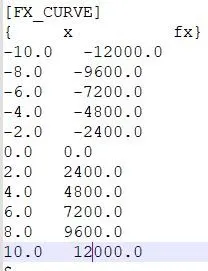
Modified Bushing Stiffnes Graph
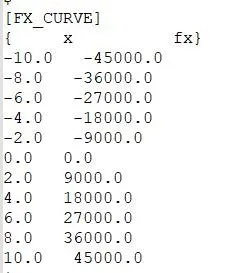
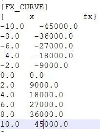
Orginal Bushin Stiffness Data
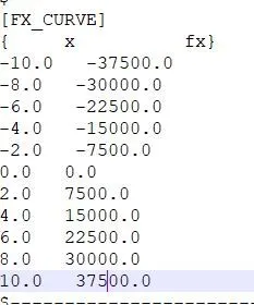
Modified Bushing Stiffness Data
Then static load simulation for 4000 N traciton for was rerunned again.
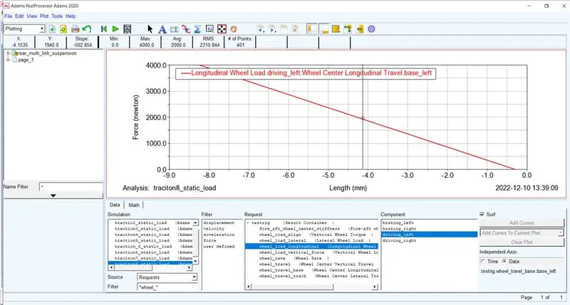
As it can be seen the new value is now 500 mm/N for Wheel Reccesion in traction.
Before achieve the camber compliance target, I change the bushing stiffness to his orgijinal value back since we can tune only one parameter at a time.
Optimizing Bushings to get Camber Compliance of 0.45 deg/KN
To optimize the Camber compliance, the bushing of upper control will be change.
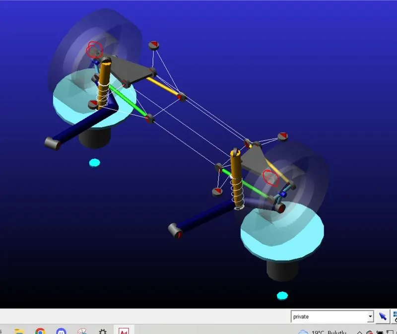
Orginal Bushing Stiffness Graph
Modified Bushing Stiffnes Graph
Orginal Bushin Stiffness Data
Modified Bushin Stiffness Data
Results
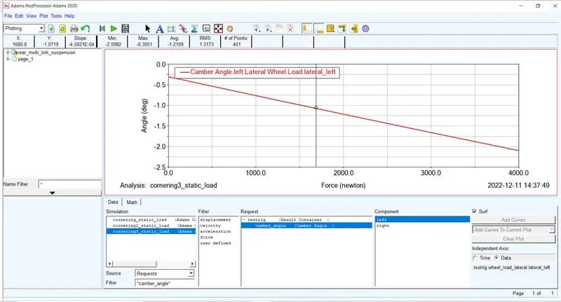
As it can be seen the new Camber Compliance is now 0.45 deg/KN.