Adams Assignments – Problem 5 – Compliance
Part 1
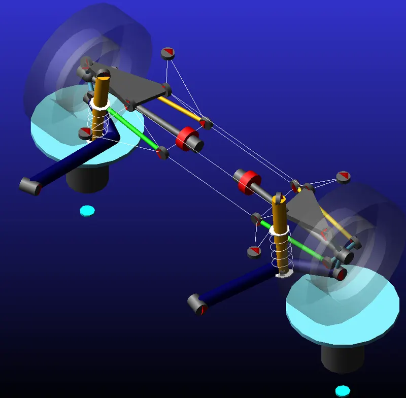
The rear multi-link assembly:
Brake Steer
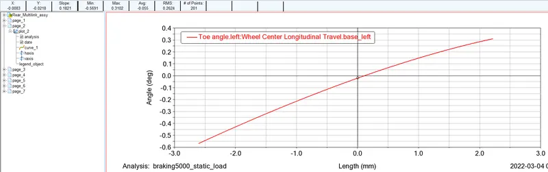
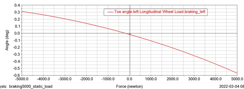
Brake force of -5000N to 5000N was applied for the analysis.
The slope of the toe angle vs brake force at zero braking force is 0.1821deg/mm. Thus, the brake steer is 182.1deg/m.
Toe angle is decreasing towards negative value with increase in braking force as can be seen in the figure below i.e. the suspension toes out during braking.
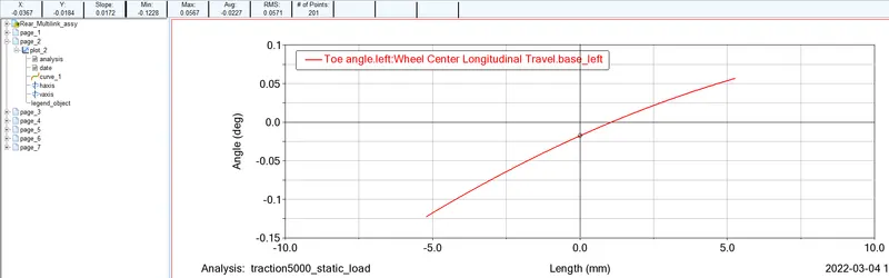
Traction Steer
Traction force of -5000N to 5000N was applied for the analysis.
The slope of the toe angle vs traction force at zero traction force is 0.0172deg/mm. Thus, the brake steer is 17.2deg/m. From the anslysis, we get toe out under traction.
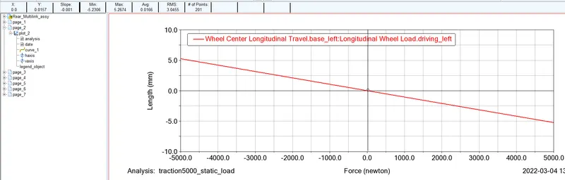
Longitudinal wheel center recession during traction
It is 0.001mm/N (slope of the graph for longitudinal wheel travel vs traction force, see below) i.e. 1mm/kN.
Longitudinal wheel center recession during braking
It is 0.0004808 mm/N (slope of the graph for longitudinal wheel travel vs braking force, see below) i.e. 0.48mm/kN.
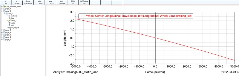
Wheel recession during traction and braking is different because traction is applied at the wheel center however braking force is applied at the wheel contact patch.
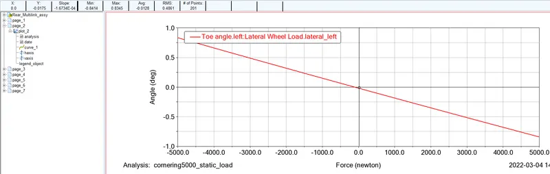
Lateral force compliance steer
From the slope of the following graph, lateral force compliance steer = 1.6734E-04 deg/N i.e. 0.164 deg/kN. The rear wheels are in toe out for positive lateral force. This causes oversteer effect.
Lateral force compliance camber
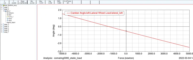
From the slope of the following graph, lateral force compliance camber = 4.0275E-04 deg/N i.e. 0.403 deg/kN. Camber is getting more negative with increasing lateral load . This causes understeer effect.
Bump Steer
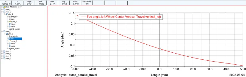
For obtaining bump steer, a parallel wheel travel is done and slope of the graph for toe angle vs wheel vertical travel is taken. From the graph below, bump steer = 0.0024 deg/mm = 2.4 deg/m. Wheel is toeing out (-ve toe angle) during jounce which gives an oversteer effect.
Part 2
Hardpoint modification for bump steer of _2.6 deg/m
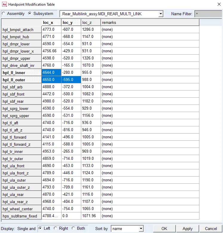
The hardpoints for the lateral links are modified as shown below to achieve the desired bump steer of 2.6 deg/m.
Suspension after hardpoint modification:
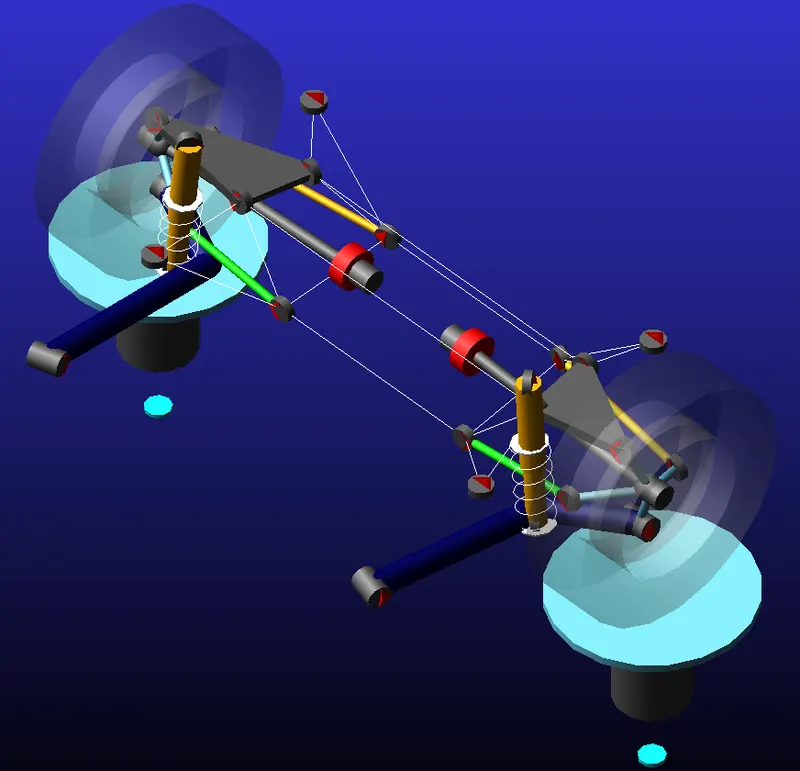
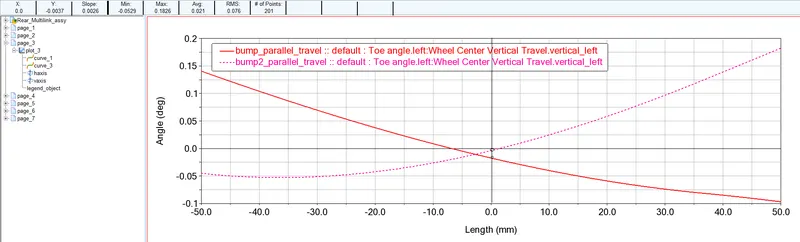
Figure below shows the toe angle variation before and after the hardpoint modification. Bump steer has changed from -2.4 deg/m to +2.6 deg/m.
Traction wheel center recession – stiffness of ~500 N/mm
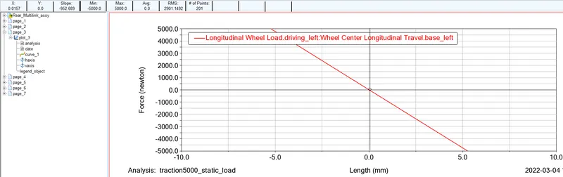
Initially, we have stiffness of about 952 N/mm (see the slope for the graph below)
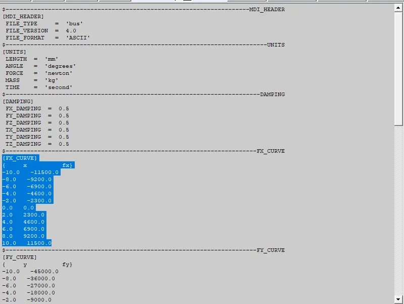
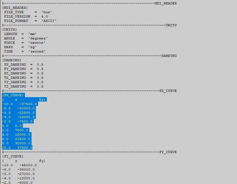
After the earlier hardpoint modification and then the change in the x-axis translational rate of the trailing link bushing from 4500N/mm t0 1150 N/mm as shown below, we achive the traction wheel center recession stiffness of 496 N/mm. The trailing link bushing property is modified because it has high impact on the wheel travel.
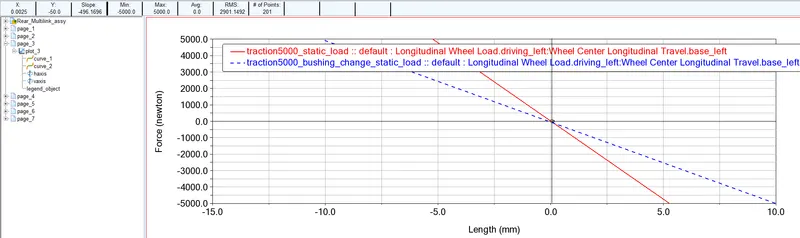
The graph below shows the traction wheel center recssion stiffness of 496 N/mm (slope of blue line).
Camber compliance of 0.45 deg/kN
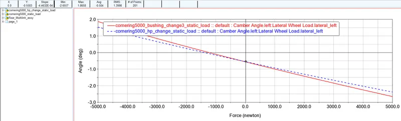
After the hardpoints modification, we had the camber compliance of 0.387 deg/kN. In order to change it to a higher value of 0.45 deg/kN, the x-axis translational stiffness of the upper control arm front bushing was lowered from 4500 N/mm to 3750 N/mm as below.
The graph below shows the camber compliance of 0.45 deg/kN (slope of red line).