YACHT
INTRODCTION:
A yacht is a watercraft used for pleasure or sports. The term originates from the Dutch word jacht (which means "hunt"), and originally referenced light, fast sailing vessels that the Dutch republic navy used to pursue pirates and other transgressors around and into the shallow waters of the Low countries. The yacht was popularized by charles of england as a pleasure or recreation vessel following his restoration in 1660.
Introduction of solid works:
Soildworks is a soild modeling computer-aided design and computer-aided engineering computer program that runs primarily on Microsoft windows. Soild works is published by dassault systemes.
Parts in yacht:
- Hull
- Garage door
- Rear seat
- Front seat
- Middle seat
- Superstructure
- Radar mast
- Propeller
DESIGN PROCEDURE
Propeller:
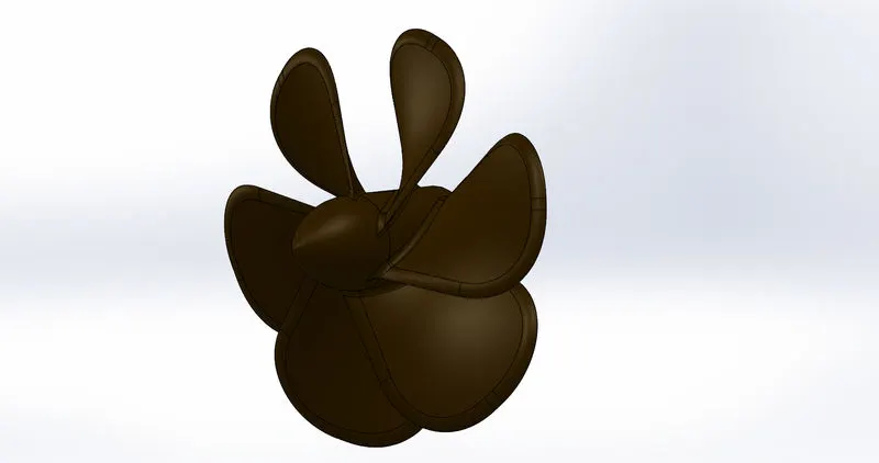
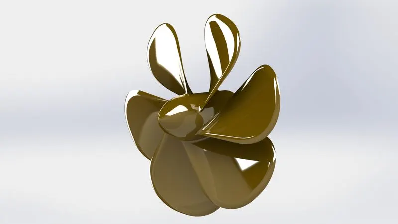
A propeller is a rotating fan like structure which is used to propel the ship by using the power generated and transmitted by the main engine of the ship. The transmitted power is converted from rotation motion to generate a thrust which imparts momentum to the water, resulting in a force that acts on the ship and pushes it forward.
Rendering image:
Rader:
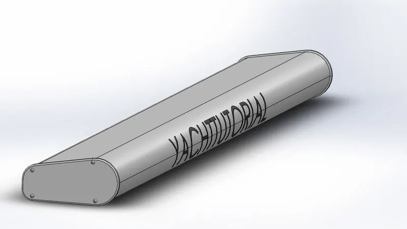
radars are X band or S band radars on ships, used to detect other ships and land obstacles, to provide bearing and distance for collision avoidance and navigation at sea. They are electronic navigation instruments that use a rotating antenna to sweep a narrow beam of microwaves around the water surface surrounding the ship to the horizon, detecting targets by microwaves reflected from them, generating a picture of the ship's surroundings on a display screen.
Rendering image:
Rader Mast:
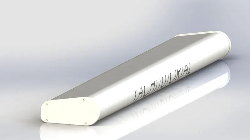
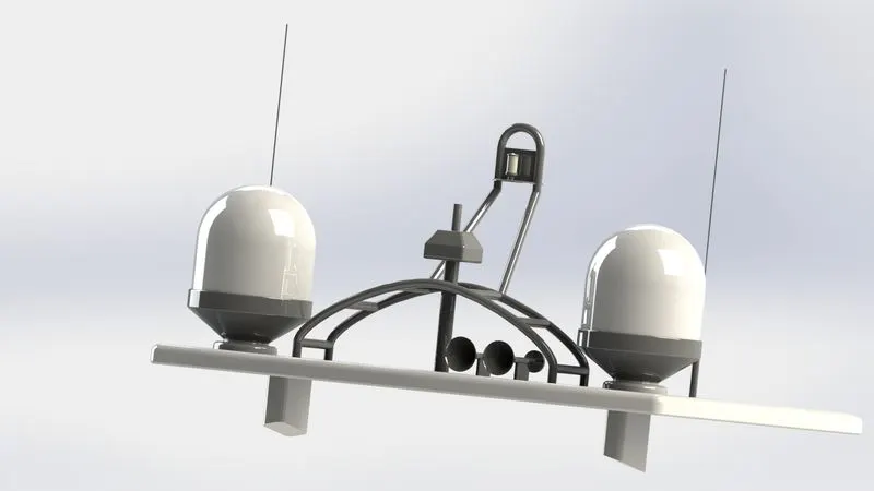
Marine radar mast has performance adjustment controls for brightness and contrast, also manual or automatic adjustment of gain, tuning, sea clutter and rain clutter suppression, and interference reduction. Other common controls consist of range scale, bearing cursor, fix/variable range marker (VRM) or bearing/distance cursor (EBL).
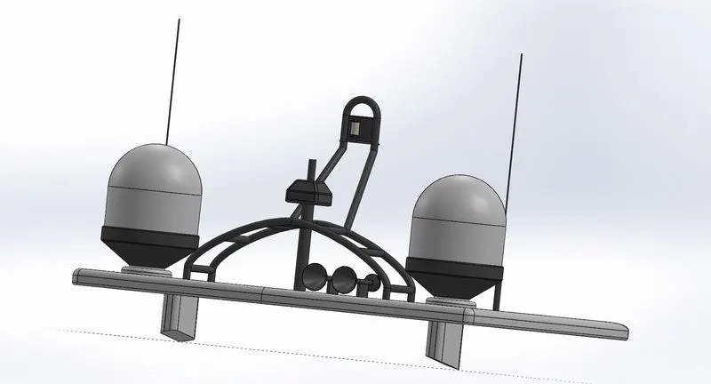
Rendering image:
Garage door:
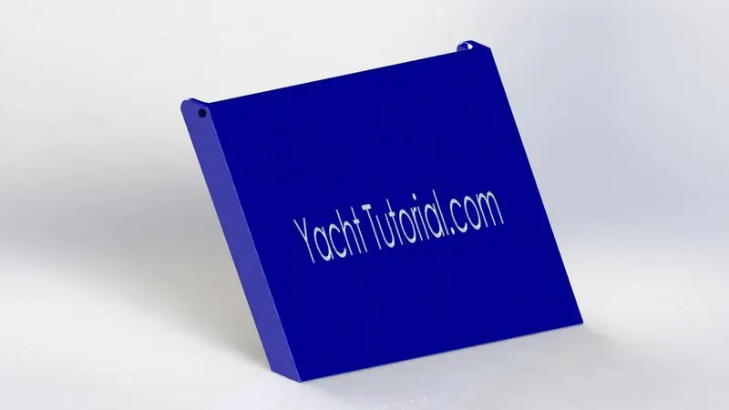
In the garage, there are two door types; there is the door that goes from the inside of the garage to the outside yard, this is just a regular exterior door you can buy easily. Then you have the door that goes from inside the garage to inside the house, this door is special, and it's called a fire door.
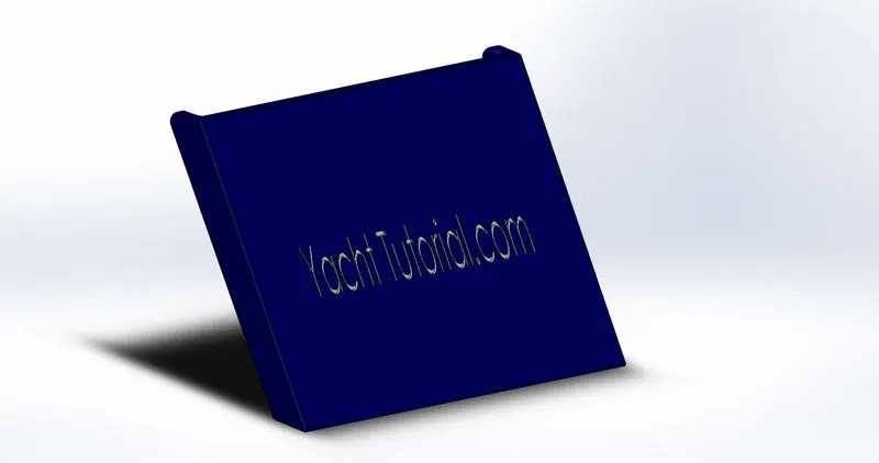
Rendering image:
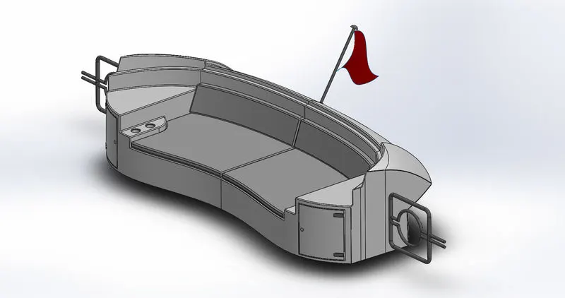
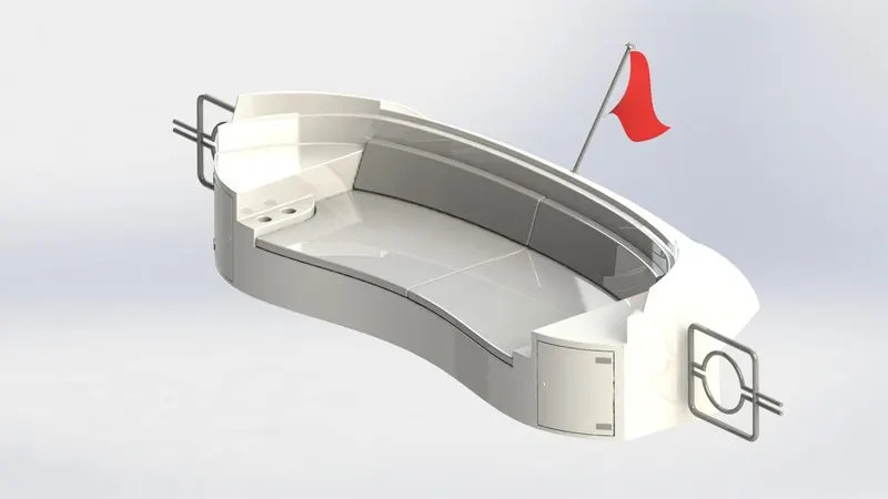
Rear seat:
This is the area where the operator and passengers sit.This seat at the rear of yatch.It has beeen designed compartively simply using soild modeling features of solidworks.
Rendering image:
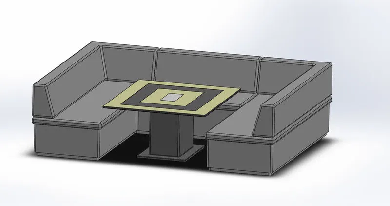
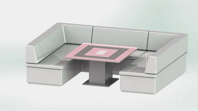
Middel seat:
This is the seat at the middel of yatch. It has been designed comparitively simply using soild modelling features of solidworks.
Rendering image:
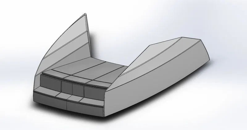
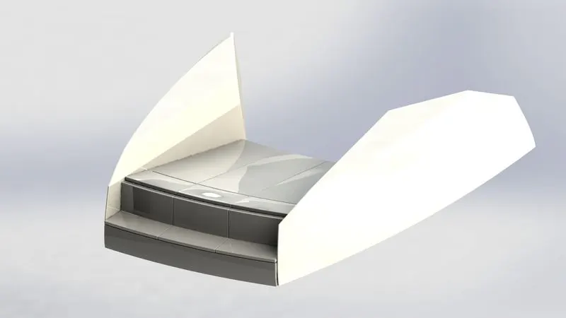
Front seat:
This is the seat at the front end of yatch.It has been designed comparitively simply using solid modelling features of solidworks.
Rendering image:
Hull:
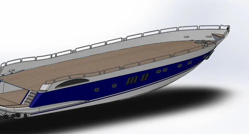
A hull is the watertight body of a ship or boat.The hull may open at top (such as a dinghy) or it may be fully or partially covered with a deck. Atop the deck may be a deckhouse and other superstructure, such as a funnel, derrick, or mast. The line where the water the hull meets the water surface is called the waterline.
Its design is also complex similar to superstructure, where many features of surface, curves and solid modelling are used to completely design the part.
Rendering image:
Superstructure:
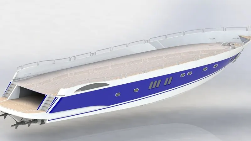
A superstructure is an upward extension of an existing structure above a baseline. This term is applied to various kinds of physical structures such as buildings, bridges, or ships having the degree of freedom zero (in the terms of terms of theory of machines).
Its is the upper portion of the yatch, inside which driver and yatch members can be seats. It has been designed by adding surfaces patch by refering to its blueprint. Finally the surfaces are solid further features are designed considering the aeerodynamic designed and stability of yatch.
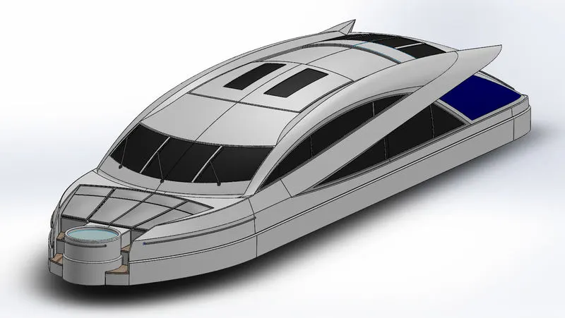
Rendering image:
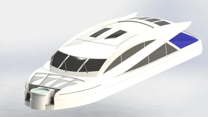
FEATURES USED
2D sketch:
Two dimensional drawings to be created with respect to a plane of view.
3D sketch:
Sketches of the model to be created in the three dimensional space.
Line:
Creates a straight line or a construction line in a sketch.
Circle:
Creates a circle in a sketch.
Rectangle:
Creates a rectangle in a sketch.
Spline:
Creates a curved line in a sketch which can be controlled using midpoints and spline direction vectors.
Arc:
Creates an arc in a sketch.
Slot:
Creates various slot shapes in a sketch.
Projection curve:
Creates a 3D curve which is projected on the basis of two 2D curves.
Offset:
Creates an offset sketch at a specified distance.
Extruded Boss:
Creates three dimensional models from two dimentional.
Extruded cut:
Removes material from a solid according to shapes given by a two dimensional sketch. It is the opposite of extrude boss.
Revolved Boss:
Creates axis-symmetric three dimentional parts from.
Fillet:
Creates a rounded edge on a part.
Chamfer:
A chamfer is an angal slope that's added along edages to make them less sharp.
Extruded surface:
Creates surface by moving a sketch along a straight path.
Swept surface:
Creates surface by moving a sketch along a curves path.
Lofted surface:
Creates a surface between multiple curves with least.
Extend surface:
Extend a surface from an edge along its direction.
Trim surface:
Trims a surface wherever required.
Knit surface:
Knit together multiple surface to form single surface.
Convert entities:
Converts projection of edges and points on to a sketch.
Swept cut:
Removes material along a curve in a specified 2D shape.
Appearance:
Gives a part the appearance of the material it is made of or of custom paints and decals.
Mirror:
Mirrors the selected parts across a specified plane.
Sweep:
Creates a 3D shape by moving a 2D shape along a sketch path.
Combine:
Uesd to combine multiple bodies to from a singal body.
Split:
Creates mutliple parts from an existing part.
ASSEMBLY:
Part modeled are assembled with respect to each other and fixed. Hull is the first part to be added. Every other part is fixed with respect to hull.
Mates feature is used to create geometric relationship between parts to fix their position and motion with respect to each other.
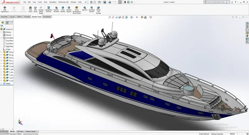
ISOMETRIC VIEW
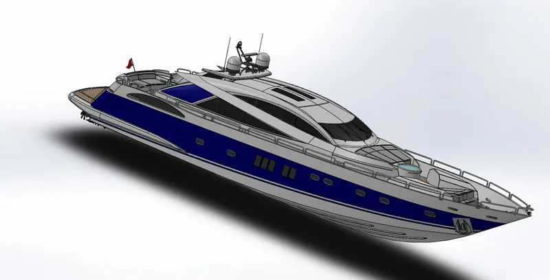
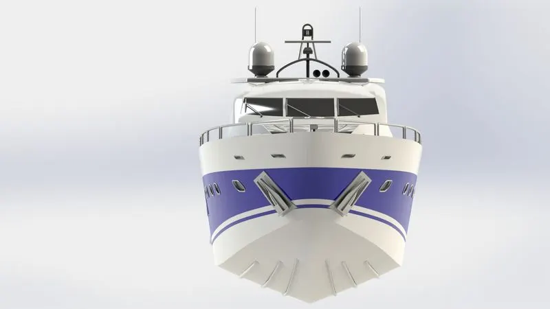
Front view
RENDERING WITH PHOTO VIEW 360
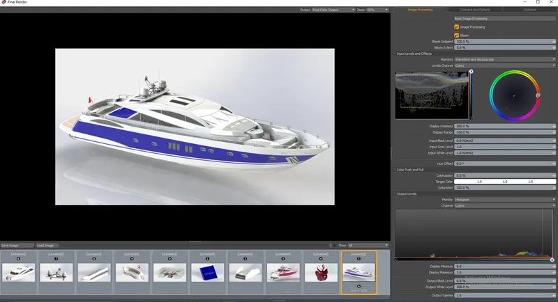
Rendering is the process in which photo realistic images are created for the model designed. The environment can be set up accroding to the needs.Background images, camere direction, enviroment settings lighting and shadows etc. can be tweaked to create the best image possible.
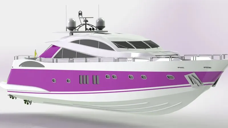
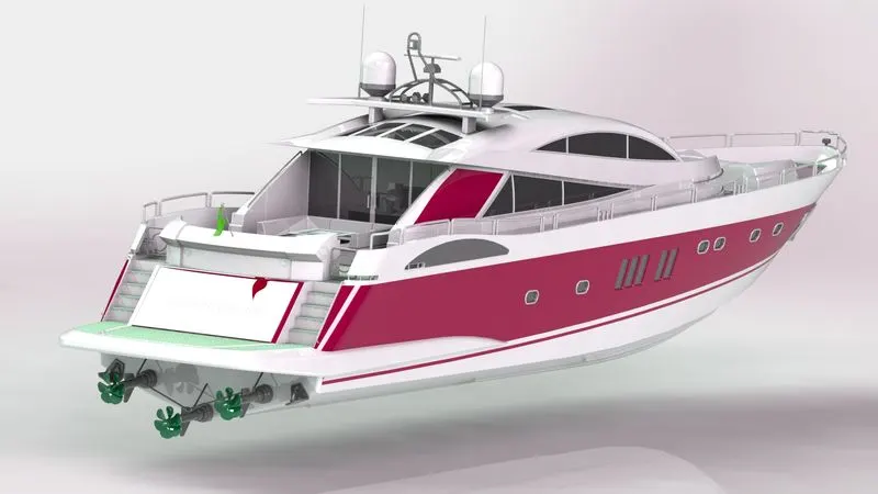
ISOMETRIC VIEW

Here is the link to access my yacht design project:
https://drive.google.com/drive/folders/16F5Ke_03jyO3zOMCF5BItLflyKOEzVFd?usp=sharing
CONCLUSION:
- Parts of a sunseeker predator yacht are designed and modeled using solidworks.
- Assembled the parts modeled using solidworks.
- Photo realistic rendering created useing solidworks photoview 360 and solidworks visulize.