SOLIDWORKS BOEING 747-8 DESIGN
AIM AND OBJECTIVE:
- To sketch and model every exterior part of the Boeing 747-8 Aircraft under the part modelling and surface modelling environment using the Solidworks.
- To assemble the modelled parts in the assembly environment.
- To create a photo-realistic rendering of the Boeing 747-8 Aircraft using Photoview 360.
WHAT IS PART MODELLING?
- Modelling in general means to create a virtual prototype of an item. It can be used for various purposes. Consider the engine of a car. Each part can be modelled separately and then can be assembled to get the engine's final form. This type of modelling is called part modelling.
PARTS TO BE MODELLED IN BOEING 747-8 AIRCRAFT:
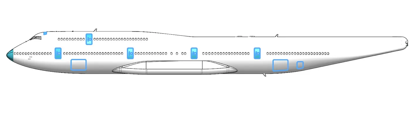
- Fuselage
- Belly Fairing
- Nose Cone
- Pitot Tubes
- Cockpit Windows
- Windshield Wipers
- Passenger Windows
- Doors and Hatches
- Lights and Antennas
- Auxiliary Power Unit
- Vertical Stabilizer
- Horizontal Stabilizer
- Wings
- Flaps and Ailerons
- Flap Track fairings
- Landing Gear Hatches Closed
- Landing Gear Hatches Open
- Wheel
- Nose Gear Base
- Nose Gear Suspension Arms
- Nose Gear Assembly
- Main Gear Base
- Main Gear Suspension Arms
- Main Gear Assembly
- Engine
- Livery
- Assembly
COMMAND USED TO CREATE THE WHOLE ASSEMBLY:
- Sketch:
- The sketch is a 2d representation of a particular from different views such as front view, side view, top view etc. The sketch comprises of commands like lines, arcs, circle etc.
- Revolve:
- Revolve is the process of creating a revolved profile about the sketch and the axis of rotation. The profile can be created with the revolution up to 360 axis rotation.
- Lofted Base:
- Creates a 3D solid or surface by specifying a series of cross-sections. The cross-sections define the shape of the resulting solid or surface. You must specify at least two cross-sections. Loft cross-sections can be open or closed, planar or non-planar, and can also be edge subobjects.
- Cut Extrude:
- The extrude cut feature is used to remove the unwanted material as per the modelled sketch. Based on the design of the sketch the material is removed.
- Fillet:
- In mechanical engineering, a fillet is a rounding of the interior or exterior corner of a part. The fillet is mainly done to uniformly distribute the stress in a specific area.
- Circular Pattern:
- The circular pattern is used to create a similar solid surface in a circular direction up to user-defined instances.
- Boss Extrude:
- The extrude command is used to create a solid extrusion based on the selected sketch or contours. The extrusion can be made in either a positive or negative direction.
- Mirror:
- The mirror command is used to create a replica of the body, feature in the specific direction up to the user-defined number of instances.
- Sketch pattern:
- The sketch driven pattern is used to create the replica of the feature, body concerning some sketch points which are created while creating the sketch itself.
- Split line:
- The Split Line tool projects an entity (sketch, solid, surface, face, plane, or surface spline) to surfaces, or curved or planar faces. It divides a selected face into multiple separate faces. You can split curves on multiple bodies with one command.
- Project curve:
- The projected curve will be available under the features tab, the project curves command can be used to create a 3d curve. The 3D curve can be created by using the reference of two 2D curves.
- Fill surface:
- Creates a surface patch within the boundary defined by existing model edges, sketches or curves.
- Surface Extrude:
- Creates an extruded surface based on some reference sketch.
- Surface Trim:
- The surface trim is used to trim the surface where one surface interacts with another surface, plane or a sketch.
- Surface extends:
- Extend the edge, multiple edge or face on a surface based on end condition and extension type.
- Shell:
- The shell feature is used to create a thickened surface. It can be done either in the interior or exterior surface.
- Chamfer:
- The chamfer command creates a bevelled feature on the selected edge, face and vertex etc.
- Sweep:
- The Sweep command is used to create solid features by sweeping a closed profile along an open or closed path.
- Dome:
- Dome, in architecture, the hemispherical structure evolved from the arch, usually forming a ceiling or roof over the surface/face being selected.
- Helix/Spiral:
- This command is present under the curves in the features tab.
- This command creates a spiral or helix based on some reference sketch.
- Delete face:
- This command is used to delete unnecessary faces and this feature comes with some options like, delete a face, delete and patch, delete and fill.
- Combine:
- The combine feature is used to create a single solid body from several existing individual solid bodies.
- Surface sweep:
- Creates a surface feature by sweeping an open or closed profile along an open or closed path.
- Surface Offset:
- Creates offset surfaces using one or more contiguous faces.
- Ruled Surface:
- The ruled surface is built by creating a swept surface using selected edges as guide curves.
- Knit Surface:
- Connecting two or more adjacent non intersecting surfaces.
PART EXPLANATION :
BLUEPRINTS:
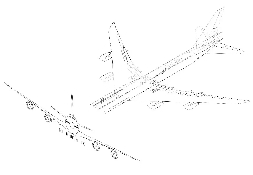
There are three different views (Front, Side & Top) used in the Blueprint Setup. By using The Sketch Picture option the images are inserted and the required dimensions are given to the images.
1.FUSELAGE:
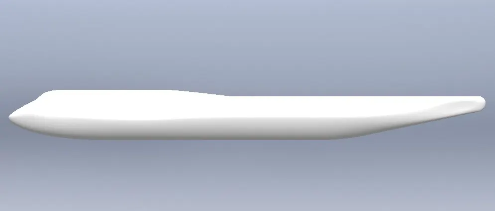
The fuselage, the central portion of the body of an Aircraft, designed to accommodate the crew, passengers, and cargo. It varies greatly in design and size according to the function of the aircraft. In a jet Fighter, the fuselage consists of a cockpit large enough only for the controls and pilot, but in a jet airliner, it includes a much larger cockpit as well as a cabin that has separate decks for passengers and cargo. The predominant types of fuselage structures are the monocoque (i.e., kind of construction in which the outer skin bears a major part or all of the stresses) and semi-monocoque. These structures provide better strength-to-weight ratios for the fuselage covering than the truss-type construction used in earlier planes.
2.BELLY FAIRING:
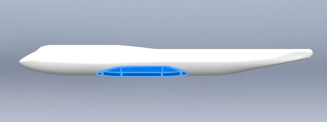
On aircraft, fairings are commonly found on Belly fairing. Also called a "ventral fairing", it is located on the underside of the fuselage between the main wings. It can also cover additional cargo storage or fuel tanks.
3.NOSE CONE:
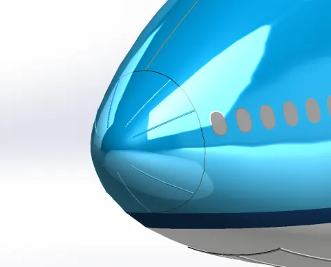
A nose cone is the forwardmost section of a rocket, guided missile or aircraft. The cone is shaped to minimize aerodynamic drag. Nose cones are also designed for travel in and underwater and in high-speed land vehicles.
4.PITOT TUBES:
A pitot tube is used in wind tunnel experiments and on aeroplanes to measure flow speed. It's a slender tube that has two holes on it. The front hole is placed in the airstream to measure what's called the stagnation pressure. The side hole measures the static pressure. By measuring the difference between these pressures, you get the dynamic pressure, which can be used to calculate airspeed.
5.COCKPIT WINDOWS:
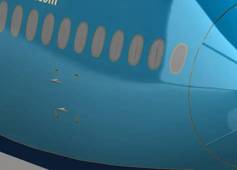
Cockpit windows may be equipped with a sun shield. Most cockpits have windows that can be opened when the aircraft is on the ground. Nearly all glass windows in large aircraft have an anti-reflective coating, and an internal heating element to melt ice.
6.WINDSHIELD WIPERS:
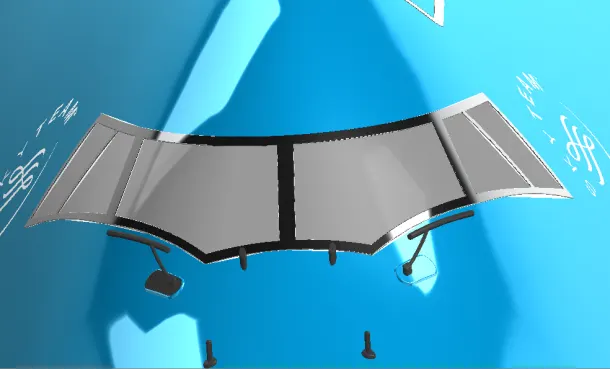
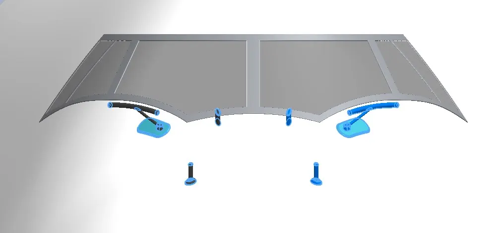
Windshield wipers, still in use even on the Boeing 747, are highly effective at sweeping rain and snow away from aircraft windshields, but with the higher speeds of jets, other innovative methods were employed to maintain good pilot visibility during approaches and departures in bad weather.
7.PASSENGER WINDOWS:
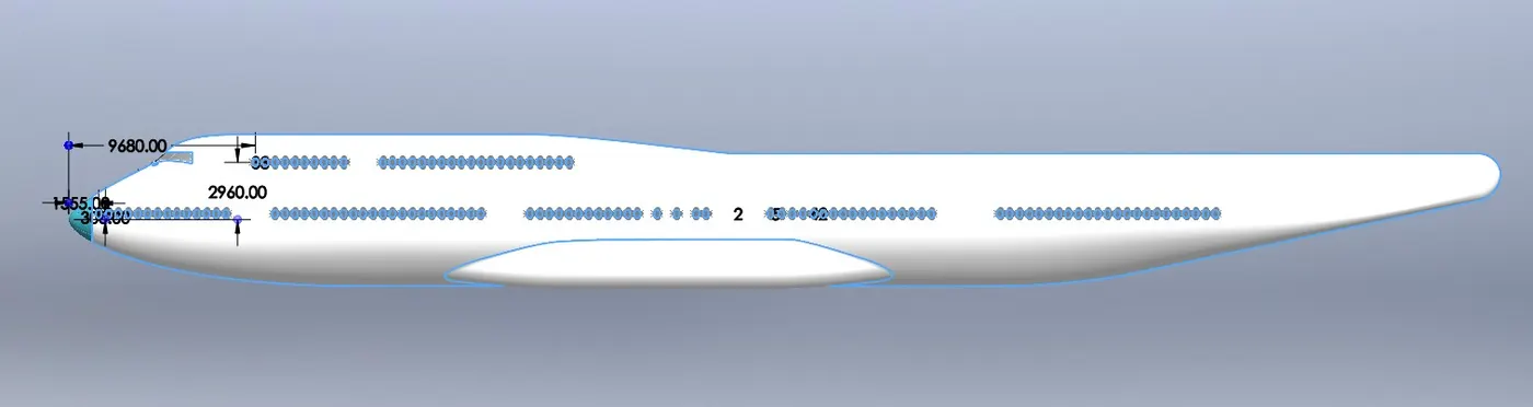
Aeroplane cabin windows consist of three layers of the window, designed to equalize the low outside pressure of the aeroplane with the high inside cabin pressure of the aeroplane.
8.DOORS AND HATCHES:
A hatch, an opening which may also be in a wall and need not be flush with the surface, is similar; in some cases either name is applicable. A small door in a wall, floor or ceiling used to gain access to equipment is called an access hatch or access door.
9.LIGHTS AND ANTENNAS:
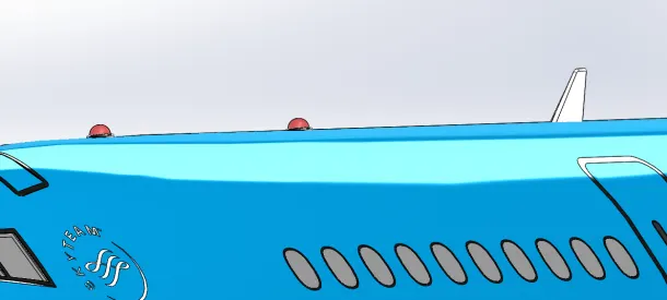
- Aircraft warning lights are high-intensity lighting devices attached to tall structures as collision avoidance measures. Such devices make structures more visible to aircraft and are usually used at night, although they may be used during the day.
- Aircraft antennas can have many different shapes and sizes, which are largely determined by the manufacturer itself. Antennas, however, are formed more for their function than anything else, and their shape and placement are usually determined by their directional qualities and the frequencies they use to operate. Essentially, these antennas need to be certain shapes and placed in certain spots to operate correctly.
10.AUXILIARY POWER UNIT:
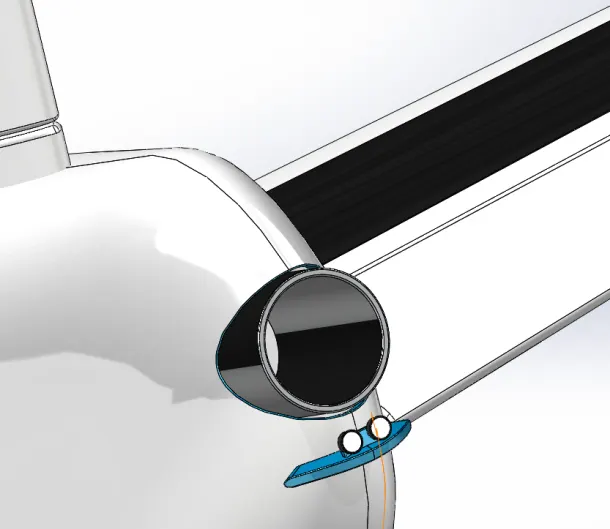
The auxiliary power unit is usually run on the ground during passenger boarding and deplaning. The APU turns an electric generator that powers the electrical system on the aircraft when the main engines are off. It also provides pneumatic pressure for air conditioning and, more importantly, starting the main engines.
11.VERTICAL STABILIZER:
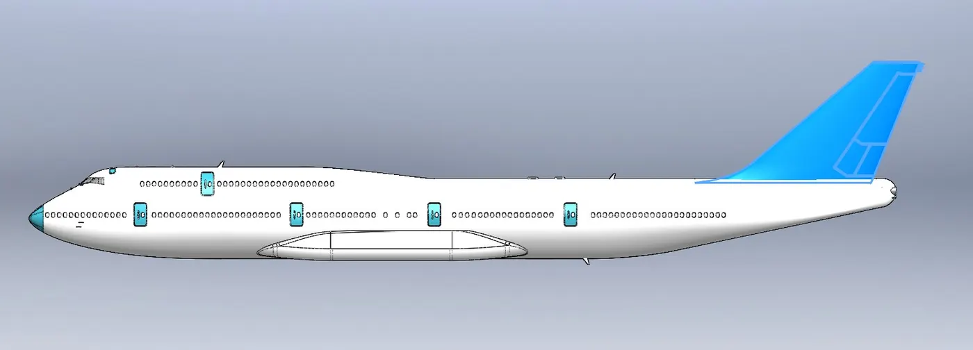
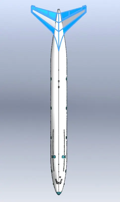
The stabilizers' job is to provide stability for the aircraft, to keep it flying straight. The vertical stabilizer keeps the nose of the plane from swinging from side to side, which is called yaw.
12.HORIZONTAL STABILIZER:
The stabilizers' job is to provide stability for the aircraft, to keep it flying straight. The horizontal stabilizer prevents an up-and-down motion of the nose, which is called pitch.
13.WING:
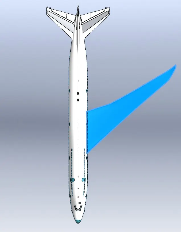
- The wings generate most of the lift to hold the plane in the air. To generate lift, the aeroplane must be pushed through the air. The air resists the motion in the form of aerodynamic drag. Modern airliners use winglets on the tips of the wings to reduce drag.
- A wing is a type of fin that produces lift while moving through air or some other fluid. As such, wings have streamlined cross-sections that are subject to aerodynamic forces and act as airfoils. ... A high lift-to-drag ratio requires a significantly smaller thrust to propel the wings through the air at sufficient lift.
14.FLAPS AND AILERONS:
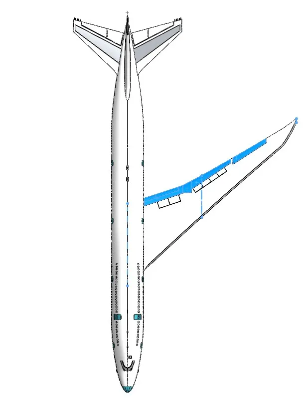
- Flaps are a kind of high-lift device used to reduce the stalling speed of an aircraft wing at a given weight. Flaps are usually mounted on the wing trailing edges of a fixed-wing aircraft. Flaps are used to reduce the take-off distance and the landing distance
- Ailerons can be used to generate a rolling motion for an aircraft. Ailerons are small hinged sections on the outboard portion of a wing. Ailerons usually work in opposition: as the right aileron is deflected upward, the left is deflected downward, and vice versa.
15.FLAP TRACK FAIRINGS:
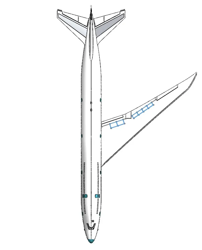
- They protect the flap retraction and extension mechanisms from elements and make the aircraft more aerodynamic by reducing the amount of interference drag acting upon the aircraft. This increases the performance and makes the aircraft efficient
- Flap Track Fairings (FTF) An aircraft fairing is a secondary structure whose primary function is to provide a cover to non-aerodynamic externally mounted mechanisms to produce a smooth outline and reduce drag.
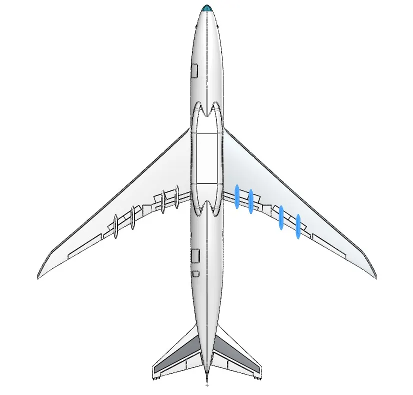
16.LANDING GEAR HATCHES:
Landing gear hatches are used to incorporate the landing gear assembly within the main body of the aircraft.
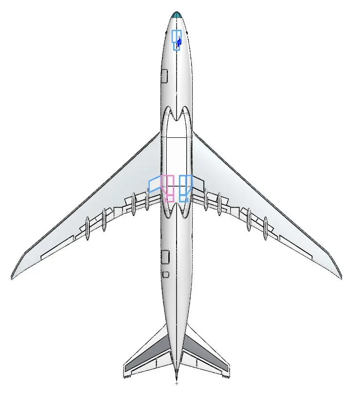
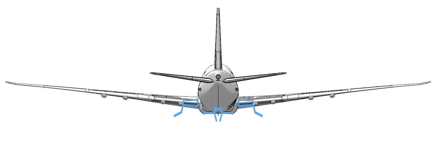
17.WHEEL :
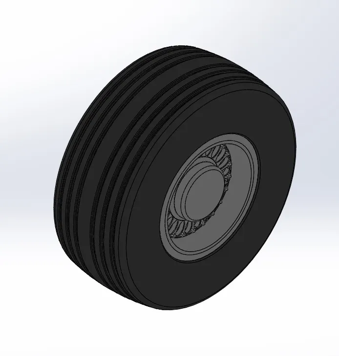
Aircraft wheels are an important component of a landing gear system. With tires mounted upon them, they support the entire weight of the aircraft during taxi, takeoff, and landing. The typical aircraft wheel is lightweight, strong, and made from aluminium alloy.
18.NOSE GEAR ASSEMBLY AND MAIN GEAR ASSEMBLY:
The landing gear is the undercarriage of an aircraft or spacecraft and may be used for either takeoff OR landing. where there are two main wheels (or wheel assemblies) under the wings and a third smaller wheel in the nose. These assemblies are used to incorporate the wheels, suspension arms inside the main body.
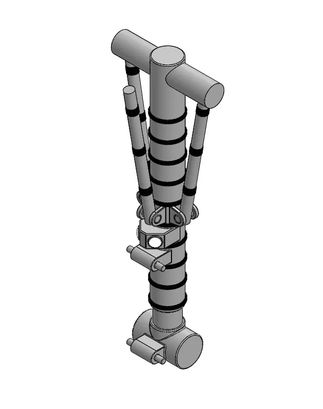
NOSE GEAR BASE
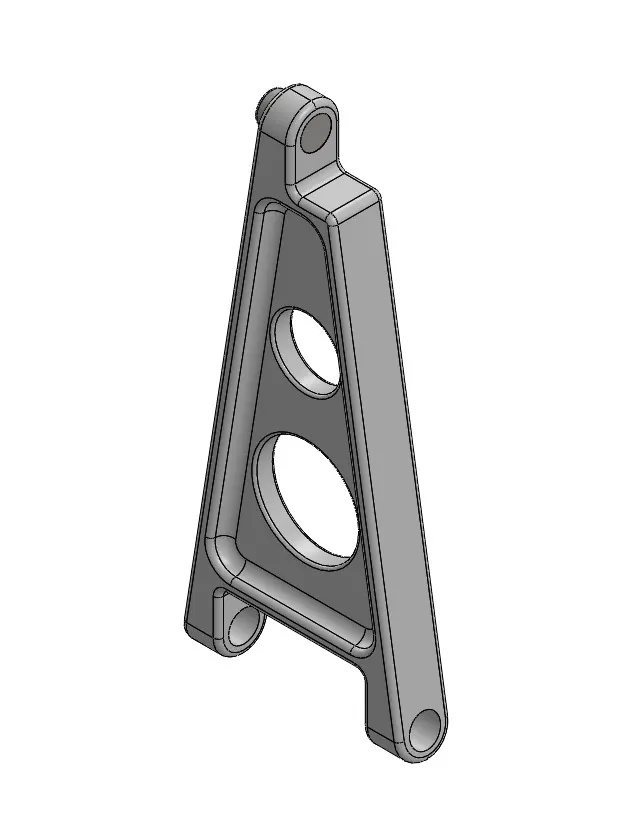
NOSE GEAR SUSPENSION ARM
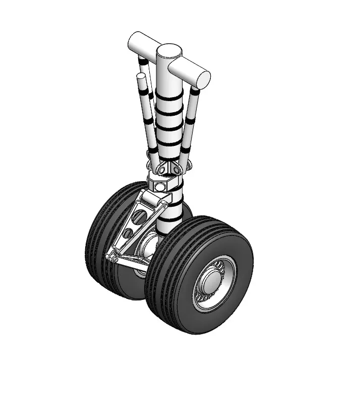
NOSE GEAR ASSEMBLY
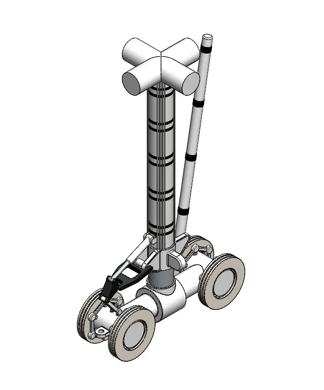
MAIN GEAR BASE
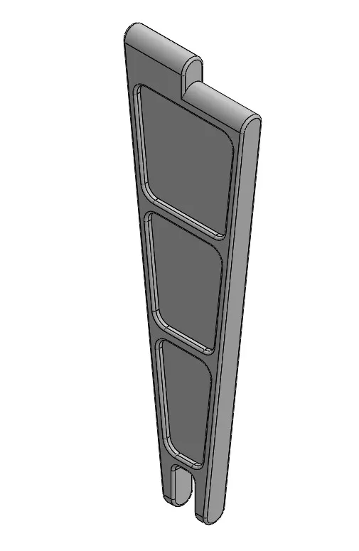
MAIN GEAR SUSPENSION ARM
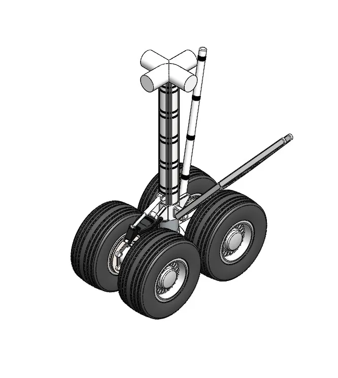
MAIN GEAR ASSEMBLY
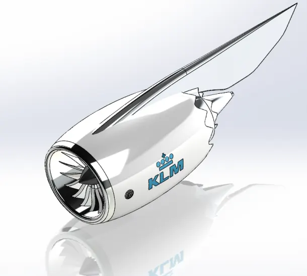
19.ENGINE:
So, the purpose of the engine is to produce two forces (thrust and lift) to overcome two other forces (weight and drag). When thrust not only exceeds drag but produces enough airflow over the wings to generate lift, you are up, up and away!
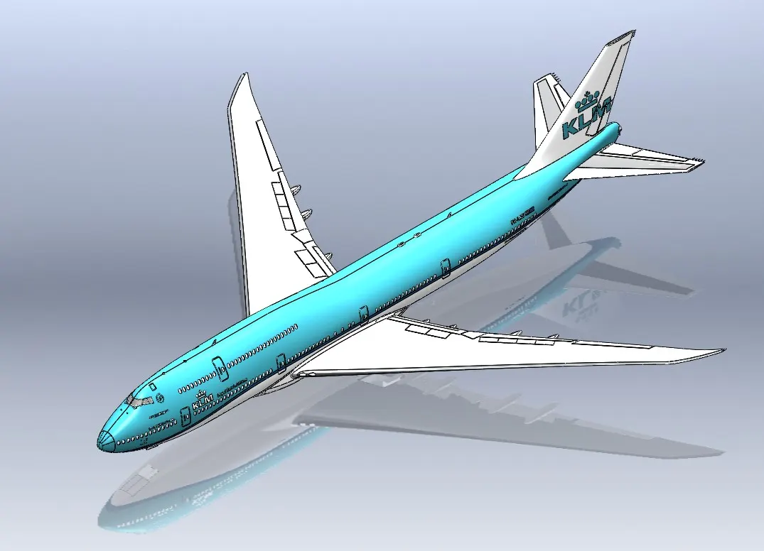
20.LIVERY:
An aircraft livery is a set of comprehensive insignia comprising colour, graphic, and typographical identifiers which operators (airlines, governments, air forces and occasionally private and corporate owners) apply to their aircraft.
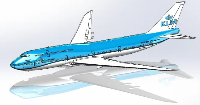
21.ASSEMBLY:
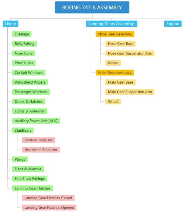
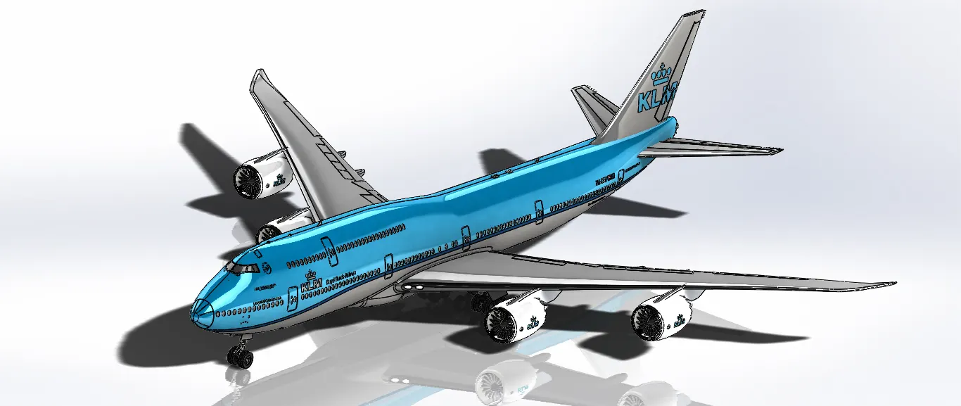
ASSEMBLY MODELED IN BOEING 747-8 :
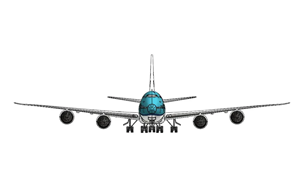
The Assembly of all the exterior parts modelled is assembled in an assembly environment.
- Nose Gear Assembly
- Main Gear Assembly
- Boeing 747-8 Assembly
CONCLUSION:
- Thus the various exterior parts of the yacht are modelled and assembled using the Solidworks software.
The outcome of course:
- Proper use of various surface and solid modelling tools in the 3D modelling environment.
- Learned how to surface model a thing and assemble its various parts in the assembly environment.