BASICS OF BIW FIXTURES - part 1
Question No.1 - What is the process of project execuion activity?
PROCESS OF PROJECT EXECUTION ACTIVITY:
Figure1. Project Activities
- The above figure shows the process involved in process execution activities.
- It is a general activities which is involved in BIW fixture & Tooling.
- It is a starting phase of every project.
- It starts with basic requirement/RFQ we received from customer.
- As shown in the figure there are various steps involved in project activities,They will be exaplained in detail below.
1. RFQ:
- RFQ - Request For Quotation.
- In this where customer gives the requirement/specifications in detail for the given projects in the form of data or documents.
- Also customer specifies its technical offer,commercial offer,etc.,how the project will be excecuted & the timeline of the project also will be mentioned.
2. FIRST SPEC. DISCUSSION MEETING:
- After RFQ received, Technical offer,commercial offer,timeline of the project,etc.,will be discussed and prepared from ourside .
- In this time required for Data study,3D design concept,simulation validation,quality check,2d drawing release,Bought outs,manufacturing,Assembly,installation & commissioning will be discussed and prepared in the technical offer.
- Based on technical offer,commercial offer will be finalized.
Figure 2. Basic example of technical offer for Manual welding fixture
Figure 3. Technical Offer for design & manufacturing of a Robotic Cell
3. OFFER SUBMISSION:
- After the finalization in the meeting,the offers will be submitted to customer end.
- Customer will arrange to get offer from other suppliers too.
- Based on the Technical,cost,quality,standard and name in the industries the customer will be finalizing the offer.
4. LOI/PO RECEIPT:
- After offer has been finalized customer will be releasing the LOI/PO (Purchase order).
- Once PO is released we have to start the work.
- After PO from the customer we have to prepare the schedule.
5. SCHEDULE PREPARATION:
- Once the PO released from customer we will be working on Preparation of schedule which should be matched our palnned committment in the technical offer/customer required time.
- Schedule preparation is nothig but dividing the different activities like Kick offmeeting, design data study,DAP,Simulate,Quality check.2D detailing,Drawing check,Release of BOM, Manufacturing,Bought outs of electrical & mechanical components,Assembly of fixture,paint,trial run out,installation and comissioning at customer end etc.,
- Thses activities will be traced in the schedule preparation chart.
- The date wise schedule should be matched the committed date. Otherwise have to revised the schedule and prepare accordingly by discussing in the meetings.
Figure 4. Example of Schedule preparation chart
6. BOM PREPARATION:
- Bill of materials like cylinders,motors,etc.,which is required for the project are prepared.
7. DESIGN CONCEPT PREPARATION:
- Before design concept, we have to study the data of constumer requirement throughly which is carried out in Design data study activities.
- During design data study ,we will be proceed with rough sketches to get a flow while designing concepts.
- The concept preparation would include the process like load act on panels,clamping process,which spot should be welded first,travel of the gun.
- In this concept preparation we should conceptualize the basic data like spot plan,cycle time etc,.
- The weld gun should not collapse while traveling,so by considering this have to make a concept preparation.
- To avoid collapses of weldgun or robots during travelling, Spot plan will be done at initial stage.
- In design concept preparation, the design of the layout are been prepared at very initial level which gives the information of placements of robots and fixtures.
Figure 5. Spot Plan
The red spot marks are the area to be welded & R1 & R2 are the robots
- Spot plan should be take in consider during concept design preparation.
- Spot plan clears us that how much robots are to be used and the sequence of the spot will be decided along with which robot will be cover certain spot places.
- Also cycle time should be considered while preparing concept design.
- To calculate the cycle time we should go to cycle time study.
- Cycle time study includes : Min. per shifts,No.of shifts,No.of days per year,No. of component per year,Total number of minutes,Efficiency,Total no. of seconds,Takt time seconds,Avg. time per spot,total no.of spot,no.of robots placed.
- From the cycle time study we can get time taken per spot,Time taken for single component,Efficiency of producion.
- If the efficiency is not satisfied we have to do some reconsideration in the design.
8. CUSTOMER APPROVAL:
- It is also known as Design Approval Process (DAP).
- After design concepts the customer will review the design concepts.
- If the design need to be made simple or some other coreection needs to be done in cocept design will be discussed and after meeting the requirement of customer,they will give approval to the design to go on with furthur activities.
9. DETAILING & DRAWING RELEASE:
- Once the customer approved the process, the detailing of the fixture parts which is to be manufactured has been done with giving appropriate dimensions and GD&T symbols.
- All the dimensions which is necessity for manufacturing should be included with GD&T in the drawings before releasing the drawing to the manufacturing team.
10. MANUFACTURING / BOP ORDERING:
- The mechanical & electrical parts like sensors,cylinders,etc.,which needs for fixture are ordered as per design specifications.
11. MECHANICAL / ELECTRICAL ASSEMBLY:
- After the materials ordered received to our end.The quality will check the working conditions and technical specs. which meets our requirement.
- After the quality check the mechanical & the electrical parts are assembled as per design.
12. QUALITY INSPECTION:
After the assembly again the quality check is done .
- In this all dimensions,positional accuracy,coordinates are checked using CMM.
13. INTERNAL TRIAL:
- After QC check internal trials are made to check the operation of the fixture.
- It is a first trial taken inhouse,So we will see by putting the assembly in the fixture whether the seating of assembly/panel suited correctly,whether the clamping operation are done properly,also whether the pins are getting intothe holes,etc,.
14. ONLINE TRIAL:
- The trail will done in automatic made through control panel.
- The process sequence of operations is checked as by the designed way.
15. PACKAGING:
- To avoid damage occur in fixtures while transportaion which may also leads to affect the Aestheic look & proper function of fixture packaging has been done.
- After the trials taken have to get the QC confirmation whether the panels met the standards/specs. given by customer also whether the fixture meets the customer standards.
- After approval of QC, Packaging is been done as per standards.Certain companies follow certain packaging standards,So the packaging should be one as per customer standards.
16. DESPATCH:
- After the fixture has been packed for delivery as per standards.
- Its been despatched to the customer.
17. INSTALLATION AS PER LAYOUT:
- As we discussed in design concept preparation, the design of the layout are been prepared at very initial level which gives the information of placements of robots and fixtures.
- According to the design the installation & commissioning team will install the fixtures.
18. TRAILS & TRAINING AT CUSTOMER:
- Production trials will be taken at customer end.
- During technical offer we will be confirmed that n-number of assemblies will be produced within 8hrs/12hrs shifts.
- So in customer trial we have to achieve the confirmed quantity of assemblies.
- Once it is achieved,trainng will be given to the operator,staffs,engineers who involved in this process.
- The sequence of working process by the fixture will be explained in detail.
- The check points which has to be done after placing the panels into the fixture will be made clear to them.
19. BUYOFF MEETING:
- After trials and training at customers end,buyoff meeting will be held.
- In this meeting customer will give reviews about the fixtures,Sometimes customer may need/feels better to do some addition work also.It will be discussed and finalize in the meeting.
20. FINAL HANDOVER:
- The fixture and the documents supports the fixtures/production will be haded over.
- Documents like poka yoke documents,clamp validation document,ergo sheets,BOMs,Charts will be delivered and handedover to customers.
- Documents will play a vital role in industry,We should always have a proof for our work done.The sequenec of qulaity of work will be seen through the documents.
- Every automobile industries will follow some standards to maintain documents as per ISO,IATF.
- Now every automobile Industries/vendors/suppliers are maintaining the documents as per IATF (International Automotive Task Force).
- IATF -The International Automotive Task Force is a group of automotive manufacturers which aims at providing improved quality products to automotive customers worldwide.
Hence, The process of project execution activities are detailed above.
Question NO. 2 - What are the types of joining process ?
Answer:
JOINING PROCESS:
- JOINING COMPRISES a large number of processes used to assemble individual parts into a larger, more complex component or assembly.
- The individual parts of a component meet at the joints.
- Joints transmit or distribute forces generated during service from one part to the other parts of the assembly.
Figure 1. Classification of joining process
TYPES OF JOINING PROCESS:
- The durability & performance of any structure is largely depend on the quality & the design of the component joints.
- Whole structure cannot be made in one piece.
- Two fundamental options for joining materials & components are,
- Metalurgical joining.
- Mechanical joining.
- Chemical joining.
A. METALURGICAL JOINING:
Metallurgical joining are classified into,
- Welding.
- Brazing.
- Soldering.
1. WELDING: The process of joining similar metals by the application of heat is called Welding.Welding can be obtained with or without application of pressure and with or without addition of filler metal,which is known as electrode.During welding, the edges of these metal pieces are either melted or brought to plastic condition.The welding process is used for making permanent joints,which is obtained by homogeneous mixture of two materials.
Classification of Welding Process: The types of welding process classified into,
- Fusion Welding.
- Electric Resistance Welding.
- Solid - state welding.
a. Fusion welding:
- In fusion welding,the metal at the joint is heated to a molten state and then it is allowed allowed to solidify.
- Pressure is not applied during the welding process and hence itis also called as 'non - pressure welding'.
- Filler materials may be required during this type of welding.
- Classification of fusion welding are,
- Thermit welding.
- Arc Welding.
- Gas Welding.
Figure 2. Fusion weld joint
1.Thermit Welding:
- Welding the parts by using liquid thermit steel around the portions to be welded is called thermit welding.Since it is a fusion welding process,neither arc is produced to heat parts nor flames are used.For getting high temperature,the exothermic reaction is used.
- Welding principle is the heat of the thermit reaction used for welding in plastic state & mechanical pressure is applied for the joint.
- It is depending on the chemical reaction between iron oxide & aluminium.
- The reaction in thermit welding is 8Al + Fe3O4 = 9Fe + 4Al2O3. This reaction takes place about 30 sec only and the heat liberation temperature is about 2800 degree celcius.It is twice the melting temperature of steel.
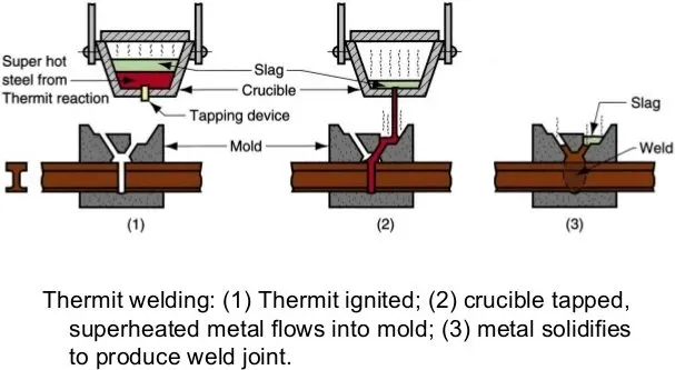
Figure 3. Thermit welding process
2.Arc Welding:
- In arc welding process,the heat is developed by an electricarc.The arc is produced between anelectrode and the work.This is a process of joining two metal pieces by melting their edges by an electric arc.In arcwelding the electrical energy is converted into heat energy.
- The electrode & the work piece are brought nearer with similar a small air gap of 3mm approximately.Then the current is passed through the work piece and the electrode toproduce an electric arc.
- The work piece is melted by an arc,The electrode is also melted and hence both the workpieces become a single piece without applying any external pressure.The temperature of arcis about 5000°C to 6000°C.The electrode supplies additional filler metal into the joints and is deposited along the joint.A transformer or generator is used to supply a current.The depth to which the metal is melted and deposited is called depth of fussion.To obtain better depth of fussion,the electrode is kept at 70° inclination to the vertical.
- Electrode used in arc welding are generally coated with a flux.The flux is used to prevent the reaction ofthe molten metal with atmospheric air.Also it removes the impurities of the molten metal and forms a slag.This slag gets deposited over the weld metal.This slag protects the weld seam from rapid cooling.
- The molten metal is forced out of the pool by electric arc.Hence a small depression is formed in the parent metal where the molten meal is oiled up.This is known as "arc carter".The distcance between the tip of the electrode and the bottom of the arc crater is called "arc length".
- The types of arc welding are,
- Manual Metal Arc welding.
- MIG Welding.
- TIG Welding.
- Submerged Arc Welding.
- Plasma Arc welding.
- Atomic hydrogen arc welding.
- Carbon Arc welding.
- Electroslag Welding.
Here I have detailed the first three types of Arc welding.
I. Manual Metal Arc Welding:
- Manual metal arc welding (MMA or MMAW) also known as shielded metal arc welding(SMAW) orinformally known as stick welding.
- Stick welding is a process where the arc is struck between the metal rod (electrode flux coated) & work piece,both the rod & the work piece surface melt to create a weld.
Figure 4. Manual Metal Arc Welding
II. MIG Welding:
- MIG Welding - Metal Inert Gas Welding.
- It is an arc welding tecnique in which a consumable electrode is used to weld two or more work piece.
- MIG welding makes use of the following components: Consumable electrode,Inert gas supply,welding head,AC or DC Supply.
Figure 5. MIG Welding
III. TIG WeLding:
- TIG Welding - Tungsten Inert Gas welding.
- It is an arc welding method that uses a non-consumeable tungsten electrode to weld two or more work pieces.
- It is very much similar to MIG Welding.
- The following components are required to perform TIG welding .They are : Power supply,Non - consumeable tungsten electrodes,Inert gas supply,Filler rod(depends on nature of work piece),welding head.
Picture 6. TIG Welding
Gas Welding:
- Gas welding is one type of welding process in which the edges of the metals to be welded are melted by using gasflame.
- No pressur is applied during welding except pressure gas welding.
- The flame is produced at the tip of the welding torch.
- The gases commonly employed for gas welding are acetylene, hydrogen, propane & butane.
- Metal 2mm to 50mm thick are welded by gas welding.
- There are three types of welding process used in industries such as,
- Oxy - acetylene welding.
- Oxy - hydrogen welding.
- Air - acetylene welding.
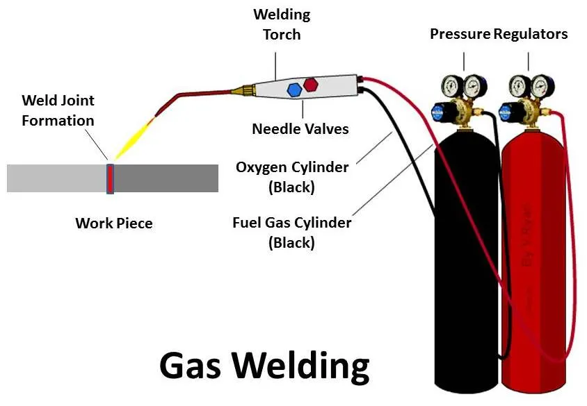
Figure 7. Gas Welding
Here I have detailed about the most commonly used gas welding
I. Oxy - acetylene welding:
- In this welding the heat is obtined by burning a mixture of oxygen & combustible gas. The gases are mixed in the required proportion in a welding torch which provides control for the welding flame. The most common form of gas welding is Oxy-acetylene welding.
- The flame only willmelt the metal. So,additional metal to the weld is supplied by the filler rod. A flux is used during weldingto prevent oxidation and to remove impurities.
- The temperature of oxy - acetylene flame in its hottest region is about 3200°C.
- The cost of acetylene is low. The gases O2,C2 & H2 can be stored at high pressure in separate steel cylinders.But the acetylene is very harmful if it is not handled carefully.
- There are two types of xy - acetylene systems employed depending upon the manner in which acetylene is supplied for welding.They are, High pressure system & Low pressure system.
- In High pressure system, both oxygen & acetylene are supplied from high pressure cylinders.
- In Low pressure system, the acetylene produced at the place of welding by interaction of calcium carbide & water in acetylene generator.
b. Electric Resistance Welding: Resistance welding is a welding technique widely used in manufacturing industry for joining metal sheets & components. This type of welding is very much used in BIW assemblies most common. The weld is made by conducting strong current through the metal combination to heat up & finally melt the metals at localized points predetermined by design of the electrodes or the work piece to be welded. A force is always applied before, during and after the application of the current to confine the contact area at the weld interfaces and in some application to forge the work piecees. Types of Resistance welding are,
- Resistance Spot welding
- Resistance Seam welding.
- Resistance Projection welding.
- Butt welding.
- Precursion welding.
Here I will discussing about only the three important types of resistance welding in detailed.
I. Resistance spot Welding:
- The process is used for joining sheet materials & uses shaped copper - chromium or zinc conium alloy electrodes to apply pressure and convey the electrical current through the work piece.
- Heat is developed mainly at the interface between two sheets, eventually causing the material being welded to melt, forming a moltel pool, the weld nugget.
- The molten pool is contained by the pressure applied by electrode tip & the surrounding solid metal.
Figure 8. Resistance Spot Welding
II. Resistance Seam Welding:
- Seam welding is a resistance welding process for joining metal sheets in continuous,often leak tight,seam joints by directly applying opposing forces with electrodes consisting of rotary wheels.
- The current & the heat generation are localized by the peripheral shapes of electrode wheels.
Figure 9. Resistance Seam Welding
III. Resistance Projection Welding:
- Projection welding is a resistance welding process for joining metal components or sheets with embossments by directly applying opposing forces with electrodes specially designed to fit the shapes of the work pieces.
- The ccurrent & the heat generation are localized by the shape of the work piece either with their natural shapes or witth specially designed projection .
- Large deformation or collapse will occurs in the projection part of the work pieces implying high.
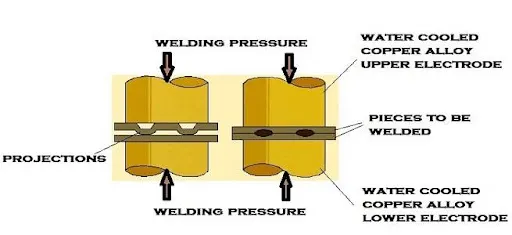
Figure 10. Resistance Projection Welding
c. Solid - State Welding: Solid State Welding is a welding process, in which two work pieces are joined under a pressure providing an intimate contact between them and at a temperature essentially below the melting point of the parent material. Bonding of the materials is a result of diffusion of their interface atoms.
The following processes are related to Solid State welding:
-
Forge welding
-
Cold welding
-
Friction welding
-
Explosive welding
- Diffusion welding
- Ultrasonic Welding
I. Forge Welding:
- Forge Welding is a Solid state welding process, in which low carbon steel parts are heated to about 1800°F (1000°C) and then forged (hammered).
Prior to Forge Welding, the parts are scarfed in order to prevent entrapment of oxides in the joint. - Forge Welding is used in general blacksmith shops and for manufacturing metal art pieces and welded tubes.
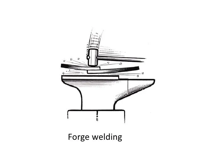
Figure 11. Forge Welding
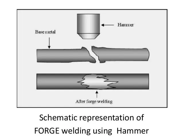
Figure 12. Forge welding
II. Cold Welding (CW):
- Cold Welding is a Solid state welding process, in which two work pieces are joined together at room temperature and under a pressure, causing a substantial deformation of the welded parts and providing an intimate contact between the welded surfaces.
- As a result of the deformation, the oxide film covering the welded parts breaks up, and clean metal surfaces reveal. Intimate contact between these pure surfaces provide a strong and defectless bonding.
- Aluminium Alloys,Copper Alloys, low carbon steels, Nickel Alloys, and other ductile metals may be welded by Cold Welding.Cold Welding is widely used for manufacturing bi-metal steel - aluminum alloy strips, for cladding of aluminum alloy strips by other aluminum alloys or pure aluminum (Corrosion protection coating). Bi-metal strips are produced by Rolling technology. Presses are also used for Cold Welding.
- Cold Welding may be easily automated.
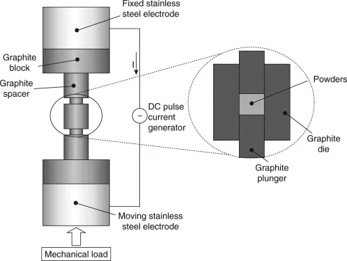
Figure 13. Cold Welding
III. Friction Welding (FRW):
- Friction Welding is a Solid state welding process, in which two cylindrical parts are brought in contact by a friction pressure when one of them rotates. Friction between the parts results in heating their ends. Forge pressure is then applied to the pieces providing formation of the joint.
- Carbon steels, alloy steels, Tool & die steels, adequate steels, aluminium alloys, copper alloys, magnesium alloys, Nickel alloys, Titanuim alloys may be joined by Friction Welding.
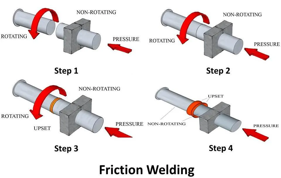
Figure 14. Friction Welding
IV. Explosive Welding (EXW):
- Explosive Welding is a Solid state welding process, in which welded parts (plates) are metallurgically bonded as a result of oblique impact pressure exerted on them by a controlled detonation of an explosive charge.
- One of the welded parts (base plate) is rested on an anvil, the second part (flyer plate) is located above the base plate with an angled or constant interface clearance.
- Explosive charge is placed on the flyer plate. Detonation starts at an edge of the plate and propagates at high velocity along the plate.
- The maximum detonation velocity is about 120% of the material sonic velocity.
- The slags (oxides, nitrides and other contaminants) are expelled by the jet created just ahead of the bonding front.
- Most of the commercial metals and alloys may be bonded (welded) by Explosive Welding.
- Dissimilar metals may be joined by Explosive Welding:Copper to steel;Nickel to steel;Aluminium to steel;Tungsten to steel;Titanium to steel;Copper to aluminum.
- Explosive Welding is used for manufacturing clad tubes and pipes, pressure vessels, aerospace structures, heat exchangers, bi-metal sliding bearings, ship structures, weld transitions, corrosion resistant chemical process tanks.
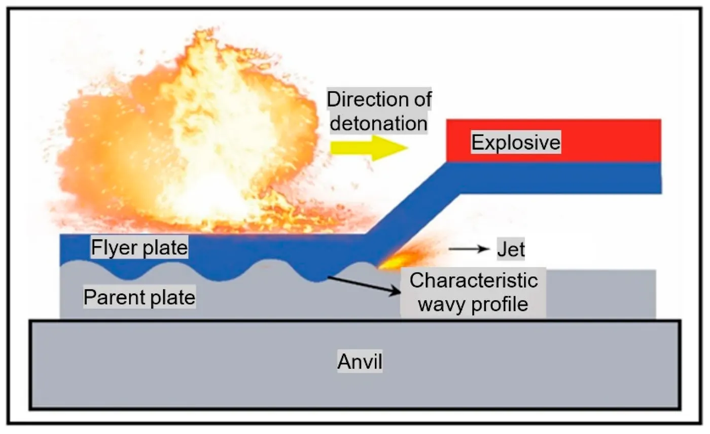
Figure 15. Explosive Welding
V. Diffusion Welding (DFW):
- Diffusion Welding is a Solid state welding process, in which pressure applied to two work pieces with carefully cleaned surfaces and at an elevated temperature below the melting point of the metals. Bonding of the materials is a result of mutual diffusion of their interface atoms.
- In order to keep the bonded surfaces clean from oxides and other air contaminations, the process is often conducted in vacuum.
- No appreciable deformation of the work pieces occurs in Diffusion Welding.
- Diffusion Welding is often referred more commonly as Solid state welding.
- Diffusion Welding is able to bond dissimilar metals, which are difficult to weld by other welding processes:Steel to tungsten;Steel to niobium;Stainless steel to titanium;Gold to copper alloys.
- Diffusion Welding is used in aerospace and rocketry industries, electronics, nuclear applications, manufacturing composite materials.
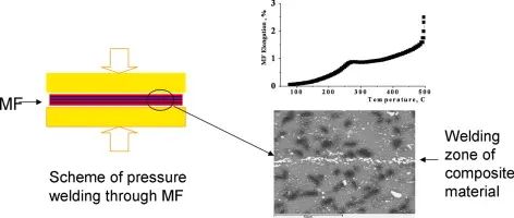
Figure 16. Diffusion Welding
VI. Ultrasonic Welding (USW):
- Ultrasonic Welding is a Solid state welding process, in which two work pieces are bonded as a result of a pressure exerted to the welded parts combined with application of high frequency acoustic vibration (ultrasonic).
- Ultrasonic vibration causes friction between the parts, which results in a closer contact between the two surfaces with simultaneous local heating of the contact area. Interatomic bonds, formed under these conditions, provide strong joint.
- Ultrasonic cycle takes about 1 sec. The frequency of acoustic vibrations is in the range 20 to 70 KHz.
- Thickness of the welded parts is limited by the power of the ultrasonic generator.
- Ultrasonic Welding is used mainly for bonding small work pieces in electronics, for manufacturing communication devices, medical tools, watches, in automotive industry.
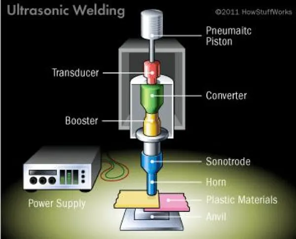
Figure 17. Ultra sonic welding
2. Brazing:
Brazing is a metal-joining process in which two or more metal items are joined together by melting and flowing a filler metal into the joint, the filler metal having a lower melting point than the adjoining metal.
Brazing differs from welding in that it does not involve melting the work pieces and from soldering in using higher temperatures for a similar process, while also requiring much more closely fitted parts than when soldering. The filler metal flows into the gap between close-fitting parts by capillary. The filler metal is brought slightly above its melting temperature while protected by a suitable atmosphere, usually a flux. It then flows over the base metal (known as wetting) and is then cooled to join the work pieces together. A major advantage of brazing is the ability to join the same or different metals with considerable strength.
There are different methos/techniques in brazing.They are:
- Torch Brazing: In this method, the acetylene, natural gas & butane or propane are combined with air or oxygen is used to supply the required heat to melt the filler rod and diffuse the base metal. It is not used for mass production and flues is used in the form of Paste or powder.
- Furnace Brazing: In this process, the heat is supplied by gas or electric heating coils. The furnace can be either box type or continuous type. The preformed shap of filler metal is placed on the parts to be joined before entering the furnace. The use of flux can be can be avoided if an inert atmosphere is maintained in the furnace. It is used for mass production and the fluxis used inthe form of paste.
- Induction Brazing: In this process also,the filler metal is used in the form of preformed shape. The parts are heated by placing within the field of high frequency induction coil. The electric and magnetic resistances of the changing induction field are used to produce the eddy current. This eddy current is used to heat the metal. It is also used for mass production and the flux is used in the form of paste.
- Dip Brazing: The dip brazing is of two types.They are: i) Chemical dip brazing: In chemical dip brazing, the parts with preformed filler metal are placed into a molten bath or flux. This method is mainly used for joining large parts. ii) Molten metal bath process: In this process, the assembled parts are first prefluxed & then immersed into a molten bath or filler metal. It is used only for joining smaller parts.
- Resistance Brazing: In this process, the filler metal is placed in the joint, Rapid heating minimizes oxidation and the heat affected zone is small.
- Laser Brazing & Electron Beam Brazing: The laser & electron beam brazing methos are costly process. In the laser brazing, the laser beam is used to join the metal and the beam produced by the heat source is used to join the metals in electron beam brazing. It is used only in precesion work of high value & relating high temperature materials.
Figure 18. Different methods of Brazing
Figure 19. Different methods of Brazing
3. Soldering:
Soldering is a process in which two or more items are joined together by melting and putting a filler metal (solder) into the joint, the filler metal having a lower melting point than the adjoining metal. Unlike welding, soldering does not involve melting the work pieces. In brazing, the work piece metal also does not melt, but the filler metal is one that melts at a higher temperature than in soldering. In the past, nearly all solders contained lead, but environmental and health concerns have increasingly dictated use of lead free alloy for electronics and plumbing purposes.
There are different types of soldering methods. They are:
- Hard soldering: In hard soldering,the filler metalis silver. It is also known as silver soldering. This method is more expensive than plain brazing because the filler metal is more expensive. This hard soldering method is used for joining electrical & refrigiration parts.
- Soft Soldering: This is the most commonly used method. In this method soldering iron is a copper rod with a thin tip which is used for flattering the soldering material. The soldering iron can be heated by keeping in a furnace or by means of an electrical resistance. The filler material used in soft soldering is called as soft solder.
- Dip soldering: In this method, a large amount of solder is melted in a closed tank. Then the parts to be soldered are cleaned & properly dipped in a flux bath as per the requirement. It is then dipped into the molten solder pool and lifted after completing soldering.
- Wave Soldering: It is a different method in which the parts to be soldered is not dipped into the solder tank but wave is generated into the tank. So the solder comes up & the joint is made. It is used for mass production of electronic equipments.
- The other methods of soldering are Oven soldering,Resistance soldering,Induction soldering & Infrared soldering.
- Resistance & Induction soldering: In this method, the electric energy is used to join the metal.
- Infrared soldering: In this method, the ultrasonic waves are used to join the metals.
Figure 20. Soldering
Figure 21. Different types of soldering methods
B. MECHANICAL JOINING: Mechanical joining includes bolting, riveting, caulking, shrink fitting, Hemming,Seaming and folding, all of which join workpieces by using mechanical energy.
I.Self Piercing Riveting:
- It is a high speed mechanical fastening process for point joining sheet material, typically steels & aluminium alloys.
- It is a single step technique generally using a semitubular rivet to clinch the sheets in a mechanical joint.
- As the name suggests pre-drilled holes are not required, allowing the joint to be made rapidly in one operation.
Figure 22. Self Piercing Revit
II. Hemming & seaming process:
- Hemming & seaming are two similar metal working process in which a sheet metal edge is rolled over onto itself.
- Hemming is a process in which the edge is rolled flush to itself, while a seam joins the edges of two materials.
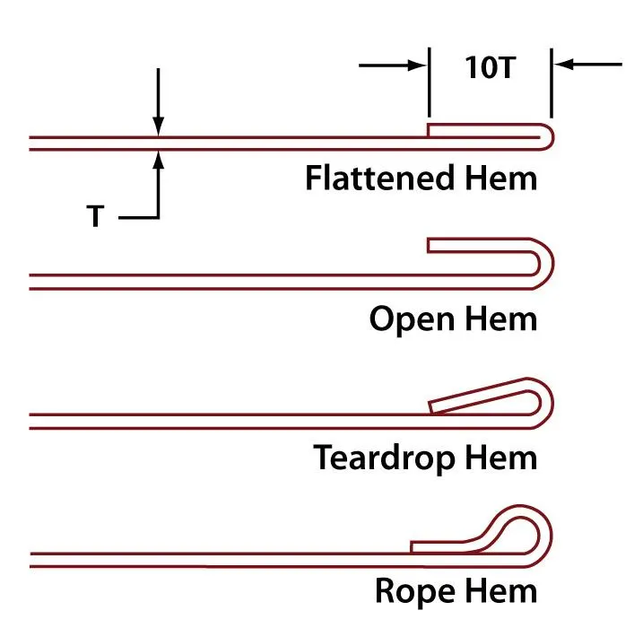
Figure 23. Hemming Process
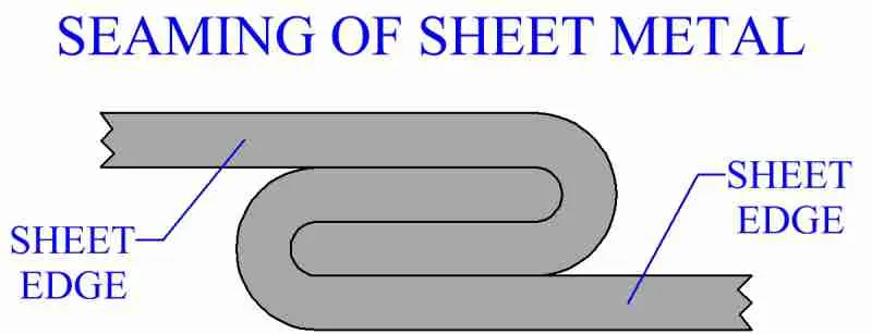
Figure 24. Seaming
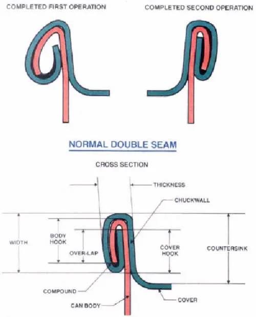
Figure 25. Seaming Process
III. Bolting:
- Bolted joints are one of the most common elements in construction and machine design. They consist of fasteners that capture and join other parts, and are secured with the mating of screw threads.
- There are two main types of bolted joint designs: tension joints and shear joints.
- In the tension joint, the bolt and clamped components of the joint are designed to transfer an applied tension load through the joint by way of the clamped components by the design of a proper balance of joint and bolt stiffness. The joint should be designed such that the clamp load is never overcome by the external tension forces acting to separate the joint. If the external tension forces overcome the clamp load (bolt preload) the clamped joint components will separate, allowing relative motion of the components.
- The second type of bolted joint transfers the applied load in shear of the bolt shank and relies on the shear strength of the bolt. Tension loads on such a joint are only incidental. A preload is still applied but consideration of joint flexibility is not as critical as in the case where loads are transmitted through the joint in tension. Other such shear joints do not employ a preload on the bolt as they are designed to allow rotation of the joint about the bolt, but use other methods of maintaining bolt/joint integrity. Joints that allow rotation include clevis linkages, and rely on a locking mechanism (like lock washer, thread adhesives, and lock nuts).
Proper joint design and bolt preload provides useful properties:
- For cyclic tension loads, the fastener is not subjected to the full amplitude of the load; as a result, the fastener's fatigue life is increased or—if the material exhibits an endurance limit its life extends indefinitely.
- As long as the external tension loads on a joint do not exceed the clamp load, the fastener is not subjected to motion that would loosen it, obviating the need for locking mechanisms. (Questionable under Vibration Inputs.)
- For the shear joint, a proper clamping force on the joint components prevents relative motion of those components and the fretting wear of those that could result in the development of fatigue cracks.
In both the tension and shear joint design cases, some level of tension preload in the bolt and resulting compression preload in the clamped components is essential to the joint integrity. The preload target can be achieved by a variety of methods: applying a measured torque to the bolt, measuring bolt extension, heating to expand the bolt then turning the nut down, torquing the bolt to the yield point, testing ultrasonically, or by applying a certain number of degrees of relative rotation of the threaded components. Each method has a range of uncertainties associated with it, some of which are very substantial.
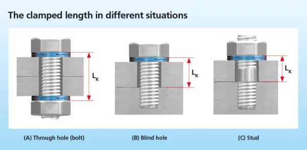
Figure 26. Bolting
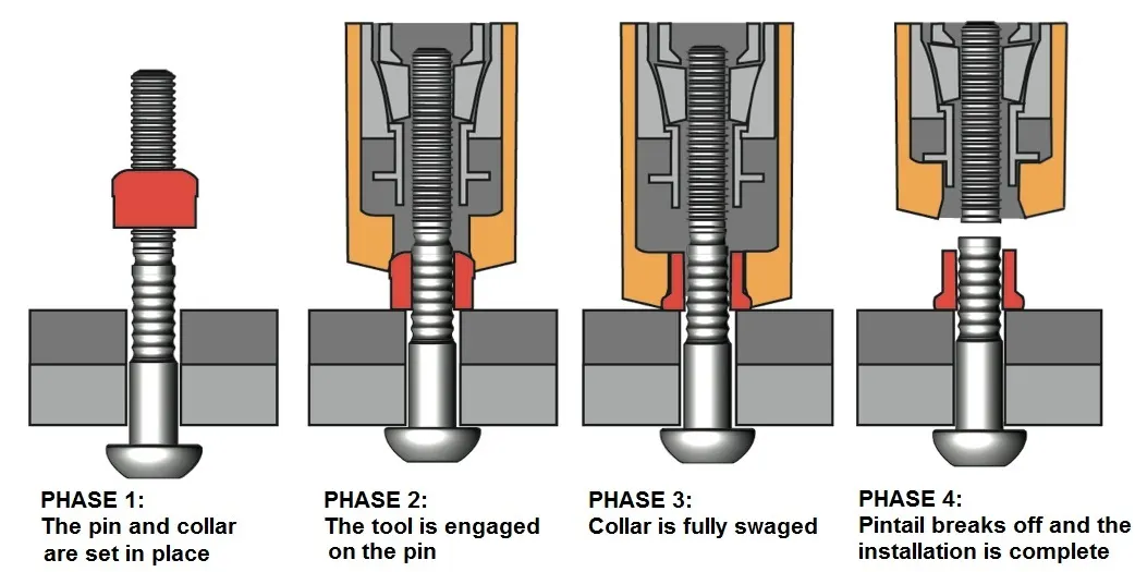
Figure 27. lock bolt
Figure 28. section view of bolt in assembly condition
IV. shrink fitting:
Shrink-fitting is a technique in which an interference fit is achieved by a relative size change after assembly. This is usually achieved by heating or cooling one component before assembly and allowing it to return to the ambient temperature after assembly, employing the phenomenon of thermal expansion to make a joint. For example, the thermal expansion of a piece of a metallic drainpipe allows a builder to fit the cooler piece to it. As the adjoined pieces reach the same temperature, the joint becomes strained and stronger.
Other examples are the fitting of a wrought iron tyre around the rim of a wooden cart wheel by a wheel wright, or of a steel tyre to the wheel of a railway engine or rolling stock. In both cases the tyre will be heated and expands to slightly greater than the wheel's diameter, and is fitted around it. After cooling, the tyre contracts, binding tightly in place. A common method used in industry is the use of induction shrink fitting which refers to the use of induction heating technology to pre-heat metal components between 150˚C and 300˚C thereby causing them to expand and allow for the insertion or removal of another component. Other methods of shrink-fitting include compression shrink fitting, which uses a cryogen such as liquid nitrogen to cool the insert, and shape memory coupling, which is achieved by means of a phase transition.
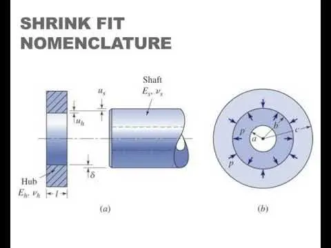
Figure 29. Shrink Fit
Figure 30. Schematic diagram of Shrink fit
C. CHEMICAL JOINING: Chemical joining includes Adhesive bondings.
Adhesive Bonding:
- Adhesive bonding is used to fasten two surfaces together usually producing a smooth bond.
- This joining technique involves glues, epoxies or various plastic agents that bond by evaporation of a solvent or by curing a bonding agent with heat, pressure or time.
- Adhesive bonding (also referred to as gluing or glue bonding) describes a wafer bonding technique with applying an intermediate layer to connect substrates of different types of materials. Those connections produced can be soluble or insoluble. The commercially available adhesive can be organic or inorganic and is deposited on one or both substrate surfaces. Adhesives, especially the well-established SU-8, and benzocyclobutene (BCB), are specialized for MEMS or electronic component production.
- The procedure enables bonding temperatures from 1000 °C down to room temperature. The most important process parameters for achieving a high bonding strength are:
- adhesive material
- coating thickness
- bonding temperature
- processing time
- chamber pressure
- tool pressure
- Adhesive bonding has the advantage of relatively low bonding temperature as well as the absence of electric voltage and current. Based on the fact that the wafers are not in direct contact, this procedure enables the use of different substrates, e.g. silicon, glass, metals and other semiconductor materials. A drawback is that small structures become wider during patterning which hampers the production of an accurate intermediate layer with tight dimension control.
- Further, the possibility of corrosion due to out-gassed products, thermal instability and penetration of moisture limits the reliability of the bonding process.
- Another disadvantage is the missing possibility of hermetically sealed encapsulation due to higher permeability of gas and water molecules while using organic adhesives.
Figure 31. Structure of Adhesive joint
Figure 32. Typical forces in adhesive joints
Hence, the types of joining process are discussed in deatil.