INTRODUCTION OF BIW FIXTURES - Part 1
Question No.1 - What is BIW & define its parts ?
Answer :
BIW:
- BIW - Body In White.
- BIW refers to the welded sheet metal components which form the vehicles structure to which the other components (like engine, chasis, exterior & interior trims) will be married or assembled.
- The stage in automotive design or automobile manufacturing in which the car body sheet metal components are been assembled by welding & by other joining process.
- The structural performance of an automobile can be determined by the performance of the body, referred to as BIW.
- BIW is the steel structural shell composed of generally steel panels welded together. BIW structure supports theoverall other subsystems in the vehicle.
- To achieve an efficient car design it is necessary to have the BIW design with optimized mass.
- BIW connected all the components in the vehicle like Powertrain, driveline.
- BIW encloses, protects the passengers & cargos. The BIW design needs to be stiff to support the mass & securely keep them all integrated. Further it needs to resist & absorb energy during the event of vehicle crash.
- BIW design also needs to be light weight structure so that there can be a posibility of reduced fuel consumption & increased performance.
- The structure is made from Steel or Aluminium panels (0.7 - 2.0 mm thickness). The pannels are stamped into shape and then spot is welded together.
- BiW constitutes about 27% of a car’s weight.
Figure 1. Exploded view of BIW components
As shown in the Figure 1, In general the BIW consists of nearly 300 - 350 components.
In the new advanced BIW architecture, the entire body was designed with 58 major parts.
MAJOR INFLUENCING FACTORS OF BIW DESIGN:
- Number of parts.
- Materials.
- Internal structural reinforcements.
The Principles that should always be Considered in BIW designs are:
- Effective load paths in the BIW architecture with minimum number of components in the design.
- Material distribution in the BIW considering the bending & torsion stiffness of the BIW.
- Internal Reinforcement location which could be lead to efficient performance increase.
- Material optimization method on a full vehicle crash analysis.
There are two types of Body structures in use, They are:
- Monocoque Body structure.
- Frame Mounted Body structure.
1.MONOCOQUE BODY STRUCTURE:
In this type of Body structures, Chasis is in built in the BIW itself and there is no seperate chasis. Wheels are directly mounted to the BIW with the help of suspension system.
Figure 2. Monocoque Body structure
2.FRAME MOUNTED BODY STRUCTURE:
In this type of body structures, Body is mounted on seperate chasis or frame & wheels are mounted on the chasis not to the body.
Figure 3. Frame Mounted body structure
BIW PARTS:
Figure 4. Classifications of BIW parts
BIW structures can be divided into following sub-structures:
- Underbody structure.
- Front End Structure.
- Body side structure.
- Closures.
- Roof.
Figure 5. BIW Parts
All those sub structures consist of following major panels:
- UNDERBODY STRUCTURE:
- Dash panel - Provides partition between Engine & the driver cabin.
- FRT Floor - Provides base for the seats.
- Raiser - Connects front floor to Rear floorby providing level difference.
- Rear Floor - Floor on the rear of the car & provides partition from ground and base for the rear seats.
- Rear wheel house.
- FRONT END STRUCTURE:
- Plenum Panel - A chamber located between throttle body & runners of the intake manifold.
- FRT Wheel House (Fender) - Is an encasement around the Front wheel.
- Wing Panel - Outer most side panel in the front.
- Cowl - Portion of the body bounded by the front fenders, the base of the wind shield and the rear edge of the hood.
- Upper Tie Bar - Upper panel in front connecting the two sides of front structures.
- Lower Tie Bar - Lower panel in front connecting the two sides of front structures.
Figure 6. Outer Panels,Inner panel,Under body panel
Figure 7. Upper body
- BODY SIDE STRUCTURE:
- A Pillar - Front most support to the roof.A- pillar are the most stylistically interesting for a car fans Other notable aspects of the A-pillar
- B Pillar - Second support to the roof. B - pillar plays a key role providing strength to a mid section to a vehicle.
- C Pillar - C is rear most support to the roof in caseof two row seating system, it will be third one. C-Pillar is often the most heavily leveraged pillar from a styling perspective. BMW has made the C - PILLAR their own distinctive curved C - pillar called the Hoffmeister kick that appears in some format in all of their cars. Coupes also rely heavily on the C-pillar to create streamlines shape.one of the most iconic is from Ford Mustang.
- D Pillar - D is the fourth support usually rear side of quarter panel. D pillar is really the end of the line in many ways this pillar is designed for the necessity to house the rear door in a wagon or SUV.
- Ring Panel - A structure panel connecting the rear & front portion.
- Quarter Panel - Rear most panel of a body side structure.
- Drip rails / Gutters - An exposed channel applied to the roof over the side windows to direct water away from the windows.
Figure 8. Classification of Pillars
From the above picture the Placements of A,B,C,D pillars can be easily understand.
Figure 9. B-Pillar
B - Pillar design and details are shown in the above picture.
Figure 10. BIW parts including with all types of pillars.
From the above picture the Roof panel & Rear quarter panel can be seen
- CLOSURES:
- All Doors
- Hoods / Bonnets - A hinged panel providing access to the engine compartment.
Figure 11. Hood
Figure 12. Door
- ROOF STRUCTURE:
- Roofs.
- Headers - Structural member above the wind shield at juncture with the forward edge of the roof panel.
- Bows.
Figure 13. Roof & Bows
REINFORCEMENT COMPONENTS:
The part which are used to support and provides stiffness and strength to other components of BIW is known as Reinforcement component. Some of the reinforcement components are shown below in the picture.
Figure 14. Reinforcement Components
PLASTIC COMPOSITE BIW / COMPOSITE CONCEPT VHICLE (CCV):
GREAT BUT FORGOTTEN IDEA "PLASTIC COMPOSITE BIW"
The Composite Concept Vehicle (CCV) is made from radically different materials to the norm, with the body being built almost entirely from plastic. the CCV will herald a new generation of lightweight, fully recyclable plastic cars that are cheap to run and extremely fuel efficient.The CCV outer body is constructed from four of the largest mouldings ever used in an automobile. These body panels are adhesively bonded to one another and then to a steel chassis, which strengthens the entire structure and supports the power train and suspension.(Chrysler's first concept car)
Figure 15. Plastic composite BIW
the CCV to be most successful in emerging countries. Thanks to reduced manufacturing costs, the vehicle will sell for about US$6000 - half the cost of its competitors. The vehicle is also virtually 100% recyclable - the plastic can be collected at the end of the vehicle's life for reprocessing.The CCV can be assembled in about 6.5 hours, compared to 19 hours for a conventional compact car. The four large body panel mouldings are part of a general design aimed at cutting the number of parts by a quarter. Overall, instead of the 80 steel components that make up a traditional chassis, the CCV only needs six plastic parts. This design should reduce manufacturing costs by as much as 80%, and plant space required for assembly could be only one sixth of that for a conventional vehicle.
The plastic body of the CCV also helps keep the vehicle light. It has a 545kg curb weight, which is approximately 50% lighter than a steel equivalent. The four body panels by themselves weigh just 95kg in total, saving more than 180kg compared to a metal body. Despite this reduced weight, the CCV is safe and strong. Its performance in cyclic load tests exceeded expectations - the body panels were expected to survive 1800 cycles, equivalent to 100,000 road miles at full vehicle weight. The test body passed 3600 cycles without significant failures. However the big panels could be moulded and that a car body made of the right thermoplastic resin can perform safely after years of rigorous testing.
The Next Stage Development:
Further resin development work will be key to the process. This will involve optimising the moulding process and determining how wide the moulding window can be while ensuring consistency and producing high quality parts and efforts to maintain the closest tolerances in the door opening and mating surfaces.
Reference from the AZoM .AZoM is the leading online publication for the Materials Science community.
MATERIALS USED IN BIW:
- High strength steels and other Ferrous materials are still mainly used in the body in white (BIW) structures of production cars.
- An alternative is the use of stronger steels with improved forming properties, which can therefore be used in thinner gauges to reduce weight. Combining different sorts of steel with different gauges in tailor made blanks has revolutionised weight saving. Apart from the BIW, there has also been an increasing trend in recent years to use other materials for car components. These include lightweight metals such as aluminium and magnesium as well as fiber reinforced polymer composites (FRPCs). All these changes have brought new challenges in joining techniques.
-
Ultra High Strength steel: In recent years, mild grades of steel have gradually been replaced by higher strength steels especially in the higher load-bearing and crash-resistant parts of the BIW.The ULSAB project, for example, has shown that, by using (U)HSS in parts of the BIW, the overall vehicle can be made safer, lighter and stiffer at a competitive price.
-
Aluminium alloys:
In Europe, BIWs made out of aluminium account for about 34 k metric tonnes of aluminium annually and, given the cost of the material, are mainly used in the lower volume/higher value segment of the automotive market.There are three main priorities for aluminium alloy research in the auto sector. The first is to increase the strength of aluminium alloys to be able to make thinner sheets. The second is to control their formability whilst the third is to improve the material’s impact resistance.
-
Magnesium:
Several parts of car bodies, for example, inside panel stiffners, have been replaced by die-cast magnesium alloys. Although their corossion resistance is rather low, the weight saving and their low melting temperature has traditionally given magnesium an advantage over aluminium alloys. They are, however, cumbersome to weld, but can be joined more easily with other joining processes like adhesive bonding or mechanical fastening.
- Fiber Reinforced Polymers ( FRP):
Joining of FRP composites can be achieved in the design of the joint, where inserts connect the parts and are (co)cured. Adhesive bonding and mechanical fastening are used as alternatives.
Figure 18. The material compositions used in BIW as been highlighted and shown by representing Pie chart
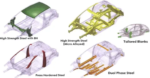
Figure 19. shows the area of different type of materials are been used
MANUFACTURING OF BIW COMPONENTS:
- STAMPING DIE DESIGN (DIE LAYOUT & OPERATION):
The BIW sheet pannels are stamped into shapes by the means of stamping Dies.The Pannel sheets are formed by applying various load in the press with the help of press tools.By achieving different sequenece of operations the BIW stamped parts are processed from blank.
Figure 20. Stamping Die
Here I have attached the different types of operations which is been used to get a final part of a sheet pannel from a plain sheet/blank.Three different types of BIW components are shown below to understand the different types of opertions involved in the Stamping process of BIW components.
Figure 21. Different types of opertions involved in the stamping process of BIW.
Some of the basics operations are ,
- Blanking
- Forming
- bending
- Drawing
- Piercing
- cutting
- Deep drwaing
For thses various operations, different types of Press tools been used which will be designed by Tool Designers and manufactured by tool makers.
In the below given picture the process plan for stamped part / BIW parts are shown by mentioning the different operations which is been indicated by different colours.
Figure 22.Process plan for stamped BIW parts
In the below given picture the sequence of operations which is been carried to complete the stamped BIW component from blanking operation to last stage operation (Complete of formed BIW component ) is shown.
Figure 23. Sequence of operation during stamping in BIW
APPLICATION OF HOT STAMPING TECHNOLOGY IN BIW PROCESS:
In recent years, automotive lightweight has led to the increasing demand of high strength steel (HSS) auto parts. Lots of correlative companies and research institutes have invested large amount of energy into the research of advanced automotive HSS forming technology. Though the advantage of HSS is high strength, it still has some disadvantages such as the poor forming performance, the uncontrollable springback, and easy to crack during forming process. Therefore, it is difficult to realize the manufacture of complex auto parts by adopting traditional cold stamping technology, where the hot stamping technology is needed.
Figure 24. Process during HOT STAMPING TECHNOLOGY of HSS
HSS hot stamping technology is a new manufacturing technology developing in recent years, which combines the traditional hot forging and cold stamping technology. It is a mode of production that integrates the stamping of steel under the condition of high temperature and forming and quenching in dies. It is also known as Hot Forming, Hot Stamping, Hot Press, Press Hardening, or Die Quenching abroad. Hot stamping technology of HSS can be used to manufacture car structural components whose tensile strength is up to 1500 Mpa, such as the front bumper, tail bumper, A&B&C PILLAR, , roof frame, underbody, door panel,and so on.
Figure 25. The proportion of hot stamping boron steel applied in VOLVO Vehicles
Hot Stamping Process
Hot stamping process is the necessary means to realize the product forming and strength increasing of hot stamping steel, and it is the indispensable premise for HSS of hot stamping to acquire high strength performance. Its typical technological process is: first, heat the sheet to a specific temperature range for austenization and austenitize it completely, and then transfer it into the water cooling hot stamping dies for stamping and quenching, and finally realize the microstructure’s phase transformation and the increase of strength. According to the complexity of processing and the forming process of actual parts, hot stamping process can be divided into directly hot stamping and indirectly hot stamping process.
1. Direct hot stamping process:
In the direct hot stamping process, a blank is heated up in a furnace, transferred to the press and subsequently formed and quenched in the closed dies.Afterwards, the product is trimmed by laser and finished through other follow-up processes.
The advantages of direct hot stamping process are as follows:
(1) The blank is formed and hardened in one mold, which saves the cost of preforming and accelerates the pace of production.
(2) The blank is flat, which not only saves heating area and energy, but also can be heated by a variety of heating methods, for example, induction heating.
The disadvantages of hot stamping process are as follows: it cannot be used for forming automobile parts with complex shapes, and it needs the laser cutting equipment. In addition, the design of cooling system of molds is more complex.For automotive body structure, the parts with simple shape, not necessary for deep drawing, can be manufactured by the direct hot stamping, such as the inside and outside pieces of b-pillar.
Figure 26. Parts with the direct method of hot stamping
2. Indirect hot stamping process
In the indirect hot stamping process, the sheet metal is performed by cold forming before it is heated to austenite temperature in a furnace. After being held for a period of time for full austenization, it will be transferred into the hot stamping tools with cooling system to be stamped and quenched at the same time. The indirect hot stamping process is also named as “multi-step”. Compared to the cold stamping steel, though the flow ability of the heated steel increases, the tensile strength would decrease accordingly, making it easy to crack for complex part during forming process. The indirect hot stamping process is the exact method invented to solve the problem and form complex BIW parts that may not be formed by the direct hot stamping process.
Compared to the direct hot stamping, the HSS sheet is uncoiled and cut according to the shape of the product, then preformed by the traditional process such as cold forming process, flanging, punching and cutting-edge, and so on. After that, the preformed semi-finished product is transferred to the continuous furnace to be heated and insulated before it is sent to be formed and quenched. Afterwards the product will be trimmed by laser processing or other necessary follow-up processes according to the characteristics of the components, or directly output finished product.
Figure 27. Parts produced by indirect hot stamping technique
The advantages of indirect hot stamping process are as follows:
(1) The parts with complex shapes and almost all of the current stamped carrying parts can be formed by indirect hot stamping process.
(2) After the performing of the blank, it is unnecessary to worry about the forming performance of the blank at high temperature in subsequent hot stamping process, which can ensure the martensite microstructure of the blank followed by complete quenching.
(3) The blank can be processed by trimming, flanging, punching and other pro-
cessing after being preformed so that it will be easier for processing after it is quenched. For example, the blank that is quenched must be trimmed by laser cutting equipment, which greatly increases the cost.
Hence, The BIW & their parts are clearly defined & discussed above.I have also slightly discussed about the Materials of BIW, Manufacturing process of BIW components like Die design and operations & Application of Hot stamping process in BIW.And also deeply talked about the New generation PLASTIC COMPOSITE BIW or COMPOSTIE CONCEPT VEHICLE (CCV) which was the Chryslers first concept car.
For PLASTIC COMPOSITE BIW Reference is from the AZoM .AZoM is the leading online publication for the Materials Science community).
Question NO. 2 - What do you understand by BIW Nomenclature?
Answer:
DEFENITION OF NOMENCLATURE:
- The devising or choosing of names for things, especially in a science or other discipline.
- In formal, the term or terms applied to someone or something.
BIW NOMENCLATURE:
- Hence from the definition of nomenclature we came to know that the terms/names applied to the BIW COMPONENTS is known as BIW NOMENCLATURE.
- The terms are standard but they differ in some countries.
- As automotive industries spread world wide, the terms and standards will be different for similar components.
- For example, One component of BIW is known as inner wing pannel in UK description otherside the same component of BIW is known as Motor compartment side panel in US description.
- Below I have been attached some common terms of BIW which differs from UK to US descriptions.
Figure 1. BIW NOMENCLATURE
Figure 2. Picture of BIW
Hence, the BIW nomenclature has been explained in detail.
Question 3 - What is fixture & its type ?
FIXTURE:
- A fixture is a device which holds the work piece to be processed (welded) by using 3-2-1 Principle.
- In general a welding fixture tool consists of Number of units together to hold the car pannel and is mounted on a base unit.
- Fixture has to be quite stable and rigid to withstand the welding stresses.
- Welding fixtures are used to hold the parts in the required shape and is used from smaller parts to larger parts of a plane. Before welding the parts are placed and positioned for the required shape. After clamping the parts by means of clamping unit welding work will be carried out.
Figure 1. Fixture
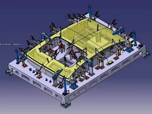
Figure 2. Fixture
FIXTURE DESIGN CRITERIA:
The criteria for designing the fixture are,
- Design specifications.
- Factory standard.
- Ease of use & safety.
- Economy.
BIW FIXTURE REQUIREMENTS:
- It should prevent dissortion in work piece during welding operation.
- The clamping need to be light but firm means the clamping force should be able to maintain the part at its required position without damaging the part.
- Placement of clamping need to be clear of welding area.
- Fixture need to be quite stable & rigid to withstand the welding stresses.
- The fixture should maintain its consistancy to do defect free operation.
3-2-1 PRINCIPLE:
Hence fixture works on the principle of 3-2-1 principle.I have detailed it below
 |
| Figure 3 . A rigid body on a space |
- X+
- X-
- Y+
- Y-
- Z+
- Z-
- Clockwise around X axis (CROT -X)
- Anticlockwise around X axis (ACROT - X)
- Clockwise around Y axis (CROT -Y)
- Anticlockwise around Y axis (ACROT - Y)
- Clockwise around Z axis (CROT -Z)
- Anticlockwise around Zaxis (ACROT - Z)
- Resting - Stability
- Locating - W.r.t datum
- Orienting - W.r.t secondary datum
- Clamping - Ensuring above not disturbed.
PRIMARY LOCATOR:
- Axial Movement downward along Z- axis ( No.6 in Fig 3 )
- Rotation about the X & Y axis ( No. 7, 8, 9 & 10 in Fig 3)
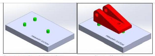 |
| Figure 4. Primary Locators |
- Axial movement along the Y+ axis ( No.3 in Fig 3 )
- Rotation about the Z axis ( No. 11 & 12 in Fig 3 )
 |
| Figure 5.Secondary Locators |
TERTIARY LOCATOR:
- Axial movement along the X axis ( No.2 in Fig 3)
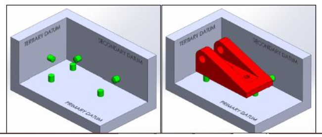 |
| Figure 6. Tertiary Locator |
- Productivity.
- Interchangeability.
- skill reduction.
- Cost reduction.
ELEMENTS OF FIXTURES:
- The fixture is the assemblies of different types of units. some of the elements / units of Fixtures are,
- Base unit: Base unit is the unit designed to mount all other units such as Clamp unit, pin unit,rest unit etc., of tool, also other parts necessary for a tool like pneumatic valve box,trunking cable path will also be mounted on to be a base unit.
Figure 7. Base unit
- Pin unit: Typically, the locating pins are used to locate a body part in a position sufficiently accurate to execute a welding process.The body part is constrained by a set of appropriately locating pin so totalconstraint by locating pin should be fully constrained at all times to prevent anymovement.
Figure 8. Pin Unit
- Clamping Unit: Clamping unit is used to clamp the part which is to be welded after location using pin unit. Clamping is achieved with the help of pneumatic cylinders and clamp arms.
Figure 9. Clamping Unit
TYPES OF FIXTURE:
- Pre-production fixture.
- Production fixture.
- Checking fixture.
PRE - PRODUCTION OPERATION (PPO) FIXTURE:
- These fixtures are designed as the prototype fixture to check & study the feasibility of initial batch production.
- This type of fixtures are used to take the trial and errors from the components.While in trial and error, the errors are absorbed and corrections are made till the part/components attains its requirement as per the drawings.
- we have to maintain the cost ofthe car as low as possible.since, Pre- production fixtures tooks more cycle time & lots of time & cost we directly move towards the Production fixture by considering standards & checklist to ensure the free production.
PRODUCTION FIXTURE:
- This type of fixture are used for Mass production purpose.
- The production fixtures must be easy for maintainance purpose.
- It should be easy to assemble and dis-assemble the parts from the fixtures to minimize the time consumption.
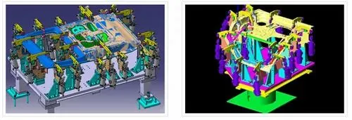
Figure 10. Production Fixture
CHECKING FIXTURE:
- As from name we understand this type of fixtures are used for the checking purpose of the part or assemblies.
- A checking fixture is used to check the automobile parts or assemblies, ensuring all the coordinates,relative dimensions & positions as per the tolerances
- A checking fixture can be a gauge type, fixed typed & automated checking fixture.
- A checking fixture is a tool where workpiece is hold & various measuring gauges are introduced to ensure the dimensions & repeatability.
Figure 11. Checking Fixture
Hence, the fixtures and its types are detailed above.
Question No. 4 - What is the Basic principle of fixture design?
Answer:
FIXTURE:
A fixture is a device which holds the work piece to be processed (welded) by using 3-2-1 principle
PRINCIPLE OF FIXTURE DESIGN:
- For a fixture designer, the major portion of design time is spent on deciding how to locate the work piece in the fixture.
- For any free body there are total 12 degrees of freedom as below,
- 6 translation degree of freedom
- X+
- X-
- Y+
- Y_
- Z+
- Z-
- And 6 rotational degree of freedom
- Clockwise around X axis (CROT -X)
- Anticlockwise around X axis (ACROT - X)
- Clockwise around Y axis (CROT -Y)
- Anticlockwise around Y axis (ACROT - Y)
- Clockwise around Z axis (CROT -Z)
- Anticlockwise around Zaxis (ACROT - Z)
- we must fix all 12 degrees of freedomin order to locate the work piece in the fixture.
- so, 12 degrees of freedom of the work piece need to be fixed & thus we can achieve zero degree of freedom for the work piece.
- Resting - Stability
- Locating - W.r.t datum
- Orienting - W.r.t secondary datum
- Clamping - Ensuring above not disturbed.
Figure 1 . A rigid body on a space
PRIMARY LOCATOR:
- Axial Movement downward along Z- axis ( No.6 in Fig 1 )
- Rotation about the X & Y axis ( No. 7, 8, 9 & 10 in Fig 1)
|
| Figure 2. Primary Locators |
- Axial movement along the Y+ axis ( No.3 in Fig 1 )
- Rotation about the Z axis ( No. 11 & 12 in Fig 1 )
|
| Figure 3.Secondary Locators |
TERTIARY LOCATOR:
- Axial movement along the X axis ( No.2 in Fig 1)
|
| Figure 4. Tertiary Locator |