DIFFERENT TYPES OF UNITS IN FIXTURE - Theory
Question No.11 - What are units ? mention 5 types of units.
Answer:
UNITS:
- In general , units is a device that has a specified function, especially one forming part of a complex mechanism.
- A welding fixtures is a assembly of different types of units.
- As name refers, the different units will be only seen in the unitized tool.
- A units are classifiend into two.They are,
1. Simple unit: In a simple welding fixture, the combination of these different units will be seen.
- Rest unit
- Fixed pin units.
- Retract pin units.
- Rough locator unit.
- Sensor unit.
- Base unit.
2. Complex unit: In a complex welding fixture, in addition with some of the simple units these complex units will also seen.
- Slide unit
- Dump unit.
Below I have mentioned some 5 types of units.
SOME FIVE TYPES OF UNITS:
i. Base Unit:
Base unit is the unit designed to mount all other units such as Clamp unit, pin unit,rest unit etc., of tool, also other parts necessary for a tool like pneumatic valve box,trunking cable path will also be mounted on to be a base unit.
Figure 1. Base unit
ii. Fixed Pin unit:
- Fixed pin unit is a unit designed to locate the car panel using pins.
- Pin, pin retainer, shims, blocks, blade, riser are the part of fixed pin units.
- pin retainer is used to hold the pin firmly.
- Typically, the locating pins are used to locate a body part in a position sufficiently accurate to execute a welding process.
- The body part is constrained by a set of appropriately locating pin so total constraint by locating pin should be fully constrained at all times to prevent anymovement.
Figure 2. Pin unit attached with sensor
iii. Retractable pin unit:
- Retractable pin unit is unit designed to locate the car panel using pins, but the entire pin package parts will be mounted on the retractable pnuematic cylinder as shown in below figure 3.
- Retractable pin unit is the opposite of fixed pin unit which can be moved up & down also which can be retracted till certain distance.
- It is mainly used for unloading the complex panel after welding.
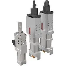
Figure 3. Rectractable pin unit
iv. Clamping unit:
- Clamp unit is a unit designed to clamp or hold the car panel with NC block/ mylars by using a pneumatic clamp cylinder.
- Clamping unit is used to clamp the part which is to be welded after location using pin unit.
- Clamping is achieved with the help of pneumatic cylinders and clamp arms.
- Clamp arm, finger, rest, shims, standard riser, pneumatic cylinder are the parts of clamping unit in general.
Figure 4. Clamping Unit
v. Slide unit:
- Slide unit is found mostly in complex fixture, where the sliding mechanism will be involved.
- This type of unit used when there is some space constraints.
- Guide block, guide rail, position lock unit, stopper block, sensors are the parts of slide unit in general.
- Guide block & guide rail helps to the guide the slide unit. The rail should always be covered to protect against weld spatter & dust by a bellow or a sheet metal cover.
- Position lock unit helps the slide to be locked/clamped in the working position.
- stopper block helps to stop/control the entire moving of a slideunit from certain distance, which is placed at the end of the guide rail.
- Sensors - The two end limits to be sensed externally by a proximity sensor.
Figure 5. Slide unit
Hence, The units are explained with some of its five types in detail.
Question No.12 - Describe fixed pin unit & their purpose.
Answer:
FIXED PIN UNIT:
- Fixed pin unit is a unit designed to locate the car panel using pins.
- Pin, pin retainer, shims, blocks, blade, riser are the part of fixed pin units in general .
- pin retainer is used to hold the pin firmly.
Figure 1. Fixed pin unit
PURPOSE OF FIXED PIN UNIT:
- As by 3-2-1 locating principle, the intoduction of two pins helps to arrest the 6 degrees of freedom (4 axial & 2 radial movements) whereas other 6 degrees of freedom are arrested by introducting minimum three supports.
- Typically, the locating pins are used to locate a body part in a position sufficiently accurate to execute a welding process.
- The body part is constrained by a set of appropriately locating pin so total constraint by locating pin should be fully constrained at all times to prevent anymovement.
Figure 2. Fixed pin unit attached with sensor
Hence, the fixed pin units & their purpose are described in short.
Question No.13 - What are the different parts of the fixed pin unit ?
Answer:
DIFFERENT PARTS OF THE FIXED PIN UNIT: The different parts of the fixed pin units are as follows,
- Pin.
- Pin retainer.
- Shims.
- Blade.
- Riser.
a. Pin:
- It is used for the location purpose of the panel.
- Typically, the locating pins are used to locate a body part in a position sufficiently accurate to execute a welding process.
- The body part is constrained by a set of appropriately locating pin so total constraint by locating pin should be fully constrained at all times to prevent anymovement.
- There are dozens of styles of locating pins that can be utilized in a design. Below I have shown the commonly used pins.
One of the most common pins is a stepped pin with either small or large head.
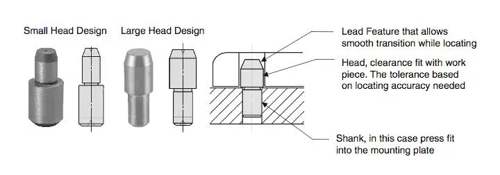
Figure 1. Locating pin
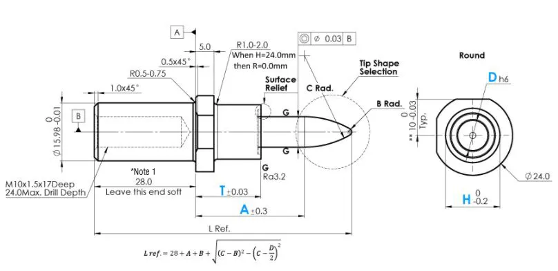
Figure 2. NAAMS standard locating pin (6 way small head) - Make: MISUMI
b. Pin retainer:
- Pin retainer is used to hold the locating pins firmly.
Figure 3. NAAMS Standard - Pin Retainer (APR 336M)
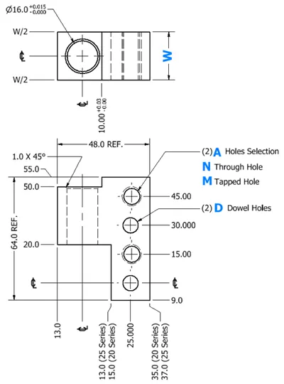
Figure 4. NAAMS Standard - Pin Retainer (APR L shaped 4-side holes)
c. Shims:
- In general, A shim is a thin and often tapered or wedged piece of material, used to fill small gaps or spaces between objects.
- Shims are typically used in order to support, adjust for better fit, or provide a level surface.
- Shims may also be used as spacers to fill gaps between parts subject to wear.
- Shims are the small parts which comes with the thickness of 0.1mm,0.2mm,0.5mm,1.0mm etc.
- These will compensate the stack up tolerance which reflects at the mylars.
- We give tolerance to all parts of the fixture.Due to this tolerance the mylars will either lift up moves down from its defined position.
- To adujust the mylars for getting the defined position we use shims.
- Shims will be added above the mylar for adjusting according to tolerance.
Figure 5. Shims
- Application of shims:
-
In automobiles, shims are commonly used to adjust the clearance or space between two parts. For example, shims are inserted into or under bucket tappets to control valve clearances. Clearance is adjusted by changing the thickness of the shim.
-
In assembly and weld fixtures precision metal shims are used between two parts so that the final production parts are created within the product drawing's specified tolerance.
- Types of shim: Types of shims are,
- wood shim.
- stone shim.
- plastic shim.
- metal shim.
- Paper shim.
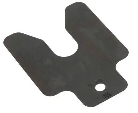
Figure 6. Shim
d. Riser:
- Riser is a manufacturing part used to raise/height the assemblies of fixtures.
- One end of the raiser will be attached to the base unit while the other end will be attached to the Blade.
- Raiser can be of two types.They are,
- 'L' type risers.
- Square tube risers.
- 'L' TYPE RISERS: 'L' type risers are of welded type.Where the stiffner will be added at the centre for support.As shown in the below figure the wedge shaped structure is known as stiffner which is used as a support / to withstand load.
Figure 7. 'L' TYPE Riser
- Square Tube Risers: Square tube raisers are of frame type.
Figure 8. Square Type Riser (Frame type)
e. Blade:
- Blade are the plates which are attached to raiser.
- Blade is also attached or mounted with cylinders,arms etc.,
Figure 9. Blade
Hence, the different parts of fixed units are explained in detail.
Question No.14 - What is a purpose of making a rest unit ? & describe its parts.
Answer:
PURPOSE OF MAKING A REST UNIT:
- Rest unit is a unit designed for the pupose to rest/support the car panel using NC block or mylars
- The mylars in rest unit is known as resting mylars.
- In this unit the part or the panel will be rested, it will not have clamps or force applied on to it .
- Rest units consist of few mylars, risers & blades.
Figure 1. Section view of Rest unit
PARTS OF REST UNIT: The parts of rest unit are as follows,
- NC block/mylars.
- Risers.
- Blades.
a. NC blocks/mylars:
- Mylars are the part which are holding the panel from top & bottom.
- It is a Jaw type, during welding it wont deforms from its position.
- It is also known as fingers.
- It dont allow the deformation of the part due to welding stresses.
- Mylars are of two types,they are
- Clamping mylars.
- Resting mylars.
- Only resting mylars can be seen in Rest unit.
- The panel which rests on the part is known as Resting Mylars.
Figure 2. NC blocks or mylars
b. Risers:
- Riser is a manufacturing part used to raise/height the assemblies of fixtures.
- One end of the raiser will be attached to the base unit while the other end will be attached to the Blade.
- Raiser can be of two types.They are,
- 'L' type risers.
- Square tube risers.
- 'L' TYPE RISERS: 'L' type risers are of welded type.Where the stiffner will be added at the centre for support.As shown in the below figure the wedge shaped structure is known as stiffner which is used as a support / to withstand load.
Figure 3. 'L' TYPE Riser
- Square Tube Risers: Square tube raisers are of frame type.
Figure 4. Square Type Riser (Frame type)
c. Blade:
- Blade are the plates which are attached to raiser.
- Blade is also attached or mounted with cylinders,arms etc.,
Figure 5. Blade
Hence, the purpose of making rest unit and the parts of rest unit are explained in detail.
Question No.15 - What are the basic fundamentals to design a sensor unit ?
Answer:
SENSOR UNIT:
- A sensor unit is a unit designed to sense the car panel by using electrical sensors.
- This signals from the sensors will be fed to the PLC and so the next process will be excecuted by this signal.
Figure 1. Sensor unit
FUNDAMENTALS TO DESIGN A SENSOR UNIT:
- Every single loose panel which are being welded in a tool should be sensed.
- Each panel should be sensed by 1 or 2 sensors depend on the size of the panel, preferred to be in diagonal opposite ends of panel.
- Every sensor should be mounted in a 3 direction adjustable way in general.
- We should try to minimize the size of sensor as much as possible.
Some major sensor manufaturers are IFM, Pepperl - fuchs, SICK, OMRON, etc.
Types of sensors used in general:
- Proximity sensor:
- A proximity sensor often emits an electromagnetic field or a beam of electromagnetic radiation (infrared, for instance), and looks for changes in the field or return signal.
- The object being sensed is often referred to as the proximity sensor's target.
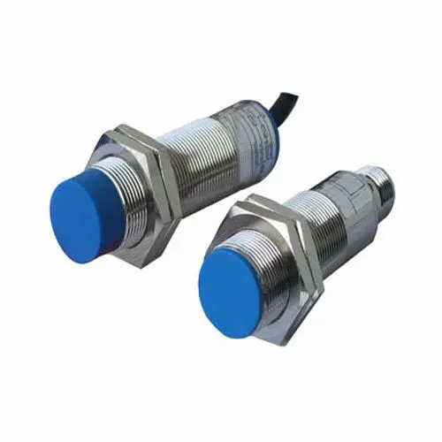
Figure 2. Proximity sensor
- Laser sensor:
- These laser distance sensors use a focused, coherent light to measure distance to a target object. In factory automation applications, the target is usually a product or a machine element. They detect any solid object and produce an output proportional to the measured distance—independent of material, color and brightness.
- The high-resolution output provided by laser distance sensors is used to provide position or displacement, usually to the input of some type of industrial controller, such as PLC. The output signal is often highly accurate, and it includes temperature compensation to enhance stability.
- There are several types of laser distance sensors including diffuse, background suppression and retroreflective. These sensors use CMOS or transit time technologies, providing accurate distance measurements.
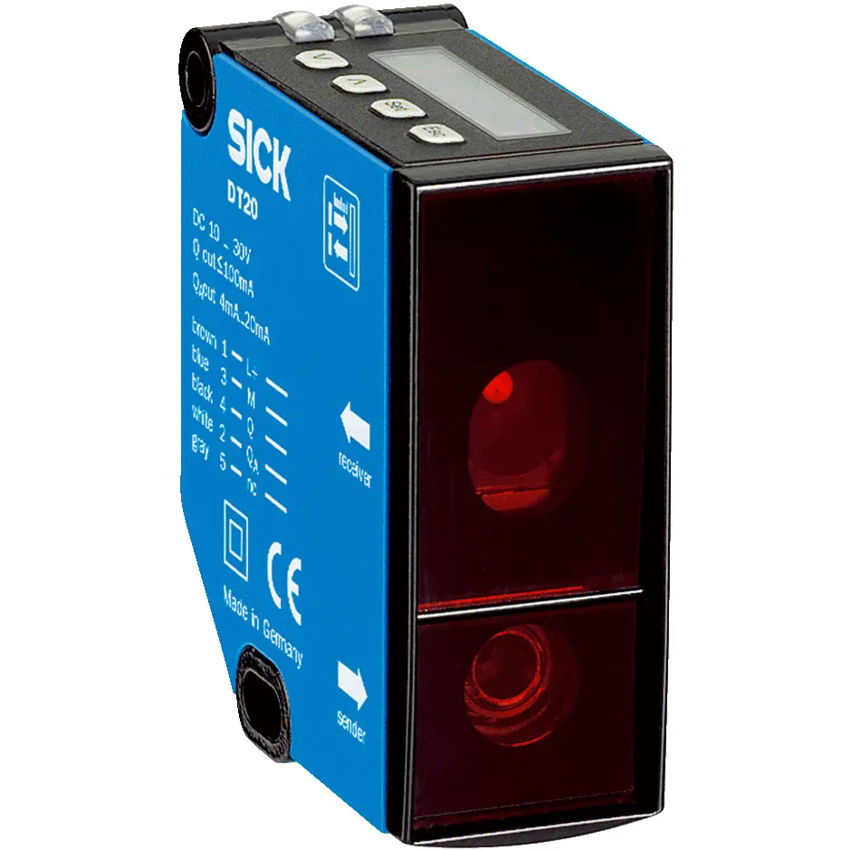
Figure 3. Laser sensor
- Photoelectric sensor:
- A photoelectric sensor, or photo eye, is an equipment used to discover the distance, absence, or presence of an object by using a light transmitter, often infrared, and a photoelectric receiver.
- They are largely used in industrial manufacturing.
- There are three different useful types: opposed (through beam), retro-reflective, and proximity-sensing (diffused).
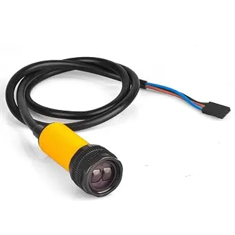
Figure 4. Photoelectric sensor
Hence, the basic fundamentals to design a sensor unit with the types of sensors are explained in detail.
Question No. 16 - What is a rough locator unit & what are the basic fundamentals to consider while designing it ?
Answer:
ROUGH LOCATOR UNIT:
- Rough locator unit is a unit designed to guide the operator to locate the car panel on to the pins accordingly.
- A rough locator can be of standard parts or make part.
Figure 1. Rough Locator (NAAMS standard)
THE BASIC FUNDAMENTALS TO CONSIDER WHILE DESIGNING A ROUGH LOCATOR:
- Rough locators should be placed at the edges of the car panel, which has to guide.
- Rough locators should be placed in the same angle of the car part edge with a minimum distance of 2 - 5 mm from the edge of the car part.
- Rough locators should guide the panels in pin assembly direction in general.
- Rough locators should start guiding the panel before 10 t0 15mm to the start of the pin engagement.
- Rough locators should be designed with entry angle for car part entry as shown in the above figure 1.
- Rough locators should be designed with two slots to mount for easy adjustments in general.
- The slots should be in the direction of car part guiding.
Figure 2. Rough locator
Hence, the rough locator unit and their basic fundamentals to consider while designing are explained clearly.
Question No. 17 - What is a base unit ? & describe its parts.
Answer:
BASE UNIT:
- Base unit is the unit designed to mount all the other units like clamp unit, pin unit, rest unit, etc. of the tool, also other parts like pneumatic valve box, truncking cable path will also be mounted on to a base unit.
Figure 1. Base unit
PARTS OF BASE UNIT: Parts of base unit are as follows,
- Valve box.
- Truncking channel.
- Measuring hole cover.
- Eye bolt.
- Pedestal.
- Floor plates.
a. Valve box:
- Valve box is basically a box which supplies air to all the pneumatic cylinders assembled in the fixture.
- Valve box consist of one solenoid valve with one inlet and one outlet.
- The outlet in solenoid valve is used to supply the air to the pneumatic cylinders from valve box.
- Whereas, the inlet in solenoid valve is used to collect the air from the pneumatic cylinders to valve box.
b. Truncking channel:
- Truncking channel is a kind of cable duct, which helps to guide and protect the wirings/tubes used in the fixtures.
Figure 2. Truncking channel
c. Measuring hole cover:
- In the measuring hole cover the co-ordinates points are engraved on it.
- The hole which mention the co-ordinates give the position & placements of the particular units.
- The measuring hole helps in CMM inspection & QC inspection.
d. Eye bolt:
- An eye bolt is a bolt with a loop at one end. They are used to firmly attach a securing eye to a structure, so that ropes or cables may then be tied to it for lifting purpose.
- Eyebolt is used to drag or lift the base unit while relocating.
Figure 3. Eye bolt
e. Pedestal:
- Pedestal is a stand like structure where the entire unit of the base will be mounted.
f. Floor plates:
- Floor plates is used to mount the entire base with the floor.
- Also it helps to achieve the flatness of the fixture.
Figure 4. Assembly of fixture highlighting the parts of base units
Hence, the base unit and their parts are explained in detail.
Question No.18 - What is dump unit & what are its functions ?
DUMP UNIT:
- Dump unit is found in complex fixture.
- Dump unit is used when there is any geometrical constraints while placing a panel.
- Dump unit consist of dump cylinder to perform clamping & unclamping.
FUNCTIONS OF DUMP UNIT:
- Dump unit plays a vital role when there is any geometrical constraints while placing a panel.
Figure 1. Dump unit
Hence, Dump unit & its functions are explained.
Question No. 19 - What are slide units ? Mention where slide units are commonly used.
Answer:
SLIDE UNITS:
- Slide units are positioning units, which are used to position the car part or panel,units,weld gun, robots for further operations.
- Slide units may be classified into two types based on the type of guide ways.They are,
- Hardend guide way.
- LM guideway.
- Slide units may further classified into three types based on the prime mover. They are,
- Manual slides.
- Hydraulic/pneumatic slides.
- CNC slides.
- It may be further classified depending on the application as
- Horizontal slide unit.
- Vertical slide unit.
- Angular slide unit.
- LM guide ways are preferred over hardend guide ways due to the least co-efficient of friction.
ESSENTIAL PARTS OF SLIDE UNIT:
- Slide unit essentially consists of guide blocks, guide rails, position lock unit, stopper block, sensors, linear cylinders.
- Guide block & guide rail helps to the guide the slide unit. The rail should always be covered to protect against weld spatter & dust by a bellow or a sheet metal cover. Guideways to be lubricated for long life.
- Position lock unit helps the slide to be locked/clamped in the working position.
- Stopper block helps to stop/control the entire moving of a slideunit from certain distance, which is placed at the end of the guide rail.
- Sensors - The two end limits to be sensed externally by a proximity sensor.
Figure 1. Slide unit in working & retracted position
Basic fundamentals of slide unit design:
- Reverse stroke of 10mm to be considered in both forward & retracted condition.
- Cylinder & LM guides to be validate for load & stroke.
- LM guide rail length should be standard & should be more than the actual stroke.
- Master guideway should be constrained & the subsidary guideway to be free.
- Mechanical hard stop to be considered for both extended & retracted condition.
- Shock absorber should be used for both extended & retracted condition to reduce impact load.
- Slide to be locked/clamped in the working position.
- Slide to be locked with a safety pin in the retracted position during transportaion.
- The two end limits to be sensed externally by a proximity switch.
- The LM rail should always be covered to protect against weld spatter & dust by a bellow or a sheet metal cover.
- The design should be checked for screw accessibilty, ease of assembly, machinability of parts.
- The LM guide & rails are integral assemblies and should not be separated at any cost.
- The shock absorber should be mounted such that it is perpendicular to the pivot at mid stroke or within +/- 5 degree.
- LM guideways to be lubricated for long life.
Figure 2. Slide unit shows alternate methods of designing a guide way
SLIDE UNITS ARE COMMONLY USED IN:
- Slide unit is found mostly in complex fixture, where the sliding mechanism will be involved.
- This type of unit used when there is some space constraints in locating the panel.
- Slide application will be easy for welding.
- Slide unit can be minimize the cost of robot as slide unit provided to move weld gun from one weld spot to other weld spot instead of weld robot
Figure 3. Slide unit
Hence, Slide unit and their common uses are explained in detail.