Air Standard Cycle - MATLAB
AIM:
To visualize P-V diagram for Air standard cycle using MATLAB
OBJECTIVE:
The objective is to find the thermal efficiency of the engine and to create a PV diagram for the cycle.
DESCRPTION:
AIR STANDARD CYCLE:
In what are known as air standard cycles, or ideal cycles, the constant volume, constant pressure and adibatic process are put together to form theoretical engine cycles which we can show on the p/V diagram. The actual p/V diagram is different from what is possible in practice, because, for instance, we assume that the gas is air throughout the cycle when in fact it may be combustion gas. We also assume that valves can open and close simultaneously and that expansion and compressions are adiabatic.
Air standard cycles are reference cycles which give an approximation to the performance of IC engines.
This is the basis of the petrol engine cycle.
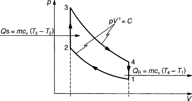
The cycle made up of an adiabatic compression, 1–2 (piston rises to compress the air in the cylinder), heat energy added at constant volume, 2–3 (the fuel burns), adiabatic expansion, 3–4 (the hot gases drive the piston down the cylinder), and heat energy rejected at constant volume, 4–1 (exhaust).
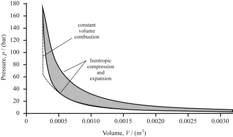
The Otto cycle is an air-standard cycle which approximates the processes in petrol or diesel engine. It is based on constant volume heat addition (combustion) and heat rejection processes, and isentropic compression and expansion. Where it is superimposed on an actual p–V diagram for a diesel engine.
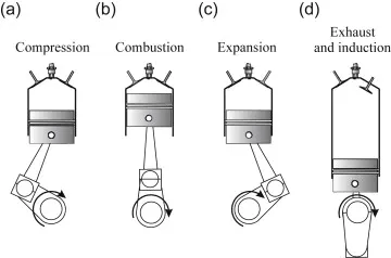
A typical engine ‘cycle’ is defined. It consists of a compression stroke, followed by a period of combustion close to top dead centre (tdc) and then by expansion. These two strokes form the power producing processes, but afterwards the products of combustion have to be replaced by fresh air. This is symbolised in where the exhaust valve is open at the beginning of the exhaust stroke. In a four-stroke engine the piston executes two complete revolutions of the crankshaft, and uses two strokes while the gas is pushed out by the piston on the up stroke, and then the intake valve is opened to enable air to be induced. In a two-stroke engine the intake and exhaust strokes occur at the end and the beginning of the expansion and compression strokes, respectively. These processes are called the gas exchange processes, and are one of the main reasons why real engines are not heat engines. The other reason is the combustion process, when the air is used to burn the fuel. This process of combustion means that the fluid in the engine cannot undergo a cycle.
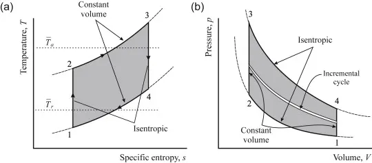
- •Isentropic compression;
- •Constant volume heat addition;
- •Isentropic expansion and
- •Constant volume heat rejection.
These can be depicted on T–s and p–V diagrams
Process 1-2: Isentropic compression
In this process, the piston moves from bottom dead centre (BDC) to top dead centre (TDC) position. Air undergoes reversible adiabatic (isentropic) compression. We know that compression is a process in which volume decreases and pressure increases. Hence, in this process, volume of air decreases from V1 to V2 and pressure increases from p1 to p2. Temperature increases from T1 to T2. As this an isentropic process, entropy remains constant (i.e., s1=s2).
Process 2-3: Constant Volume Heat Addition:
Process 2-3 is isochoric (constant volume) heat addition process. Here, piston remains at top dead centre for a moment. Heat is added at constant volume (V2 = V3) from an external heat source. Temperature increases from T2 to T3, pressure increases from p2 to p3 and entropy increases from s2 to s3.
In this process,
Heat Supplied = mCv(T3 – T2)
where,
m → Mass
Cv → Specific heat at constant volume
Process 3-4: Isentropic expansion
In this process, air undergoes isentropic (reversible adiabatic) expansion. The piston is pushed from top dead centre (TDC) to bottom dead centre (BDC) position. Here, pressure decreases fro p3 to p4, volume rises from v3 to v4, temperature falls from T3 to T4 and entropy remains constant (s3=s4).
Process 4-1: Constant Volume Heat Rejection
The piston rests at BDC for a moment and heat is rejected at constant volume (V4=V1). In this process, pressure falls from p4 to p1, temperature decreases from T4 to T1 and entropy falls from s4 to s1.
Total Cylinder Volume:
It is the total volume (maximum volume) of the cylinder in which Otto cycle takes place. In Otto cycle,
Total cylinder volume = V1 = V4 = Vc + Vs
where,
Vc → Clearance Volume
Vs → Stroke Volume
Clearance Volume (Vc):
At the end of the compression stroke, the piston approaches the Top Dead Center (TDC) position. The minimum volume of the space inside the cylinder, at the end of the compression stroke, is called clearance volume (Vc). In Otto cycle,
Clearance Volume, Vc = V2
Stroke Volume (Vs):
In Otto cycle, stroke volume is the difference between total cylinder volume and clearance volume.
Stroke Volume, Vs = Total Cylinder Volume – Clearance Volume = V1 – V2 = V4 – V3
Compression Ratio:
Compression ratio (r) is the ratio of total cylinder volume to the clearance volume.
Now that we know the basic terms, let us derive expressions for T2 and T3. These expressions will be useful for us to derive the expression for air-standard efficiency of otto cycle. For finding T2, we take process 1-2 and for finding T3, we take process 3-4.
Process 1-2:
This process is an isentropic (reversible adiabatic) process. For this process, the relation between T and V is as follows:
Process 3-4:
This is also an isentropic process. The relation between T and V in this process is similar to the relation between T and V in process 1-2:
Here,
Air-standard efficiency of Otto cycle:
It is defined as the ratio between work done during Otto cycle to the heat supplied during Otto cycle.
Air-Standard Efficiency (thermal efficiency) of Otto cycle,
clear all
close all
clc
%inputs
gamma = 1.4
t3 = 3000
%state variables at point 1
p1 = 135500;
t1 = 600;
%engine geometric ratio
bore = 0.4;
stroke = 0.4;
con_rod = 1;
c_r = 10;
%formulas for swept volume and clearance volume
v_s = (pi/4)*bore^2*stroke;
v_c = v_s/(c_r-1);
v1 = v_s + v_c
v2 = v_c
%state variables at point 2
%p2v2^gamma = p1v1^gamma
p2 = p1*c_r^gamma
%p1v1/t1 = p2v2/t2
t2 = (p2*v2*t1)/(p1*v1)
constant_c = p1*(v1^gamma)
V_compression = engine_kinematics(bore,stroke,con_rod,c_r,180,360)
P_compression = constant_c./V_compression.^gamma
%state variables at point 3
v3 = v2
%p3v3/t3 = p2v2/t2
p3 = (p2*t3)/t2
constant_c = p3*(v3^gamma)
V_expansion = engine_kinematics(bore,stroke,con_rod,c_r,0,180)
P_expansion = constant_c./V_expansion.^gamma
%state variables at point 4
v4 = v1
%p3v3^gamma = p4v4^gamma
p4 = p3*(v3/v4)^gamma
%t4/p4v4 = t3/p3v3
t4 = (t3*p4*v4)/(p3*v3)
%thermal efficiency
thermal_efficiency = 1-((c_r)^(1-gamma))
figure(1)
hold on
plot(v1,p1,'*','color','r')
plot(V_compression,P_compression,'color','r')
plot(v2,p2,'*','color','r')
plot(v3,p3,'*','color','r')
plot(V_expansion,P_expansion,'color','g')
plot(v4,p4,'*','color','r')
plot([v1 v1],[p1 p4])
plot([v2 v2],[p2 p3])
xlabel('volume')
ylabel('pressure')%engine kinematics
function [V] = engine_kinematics( bore, stroke, con_rod, c_r, start_crank, end_crank)
%inputs
a = stroke/2
R = con_rod/a
theta = linspace(start_crank,end_crank,250);
v_s = (pi/4)*bore^2*stroke;
v_c = v_s/(c_r-1);
%formula
%V/v_c = 1+0.5(c_r - 1)(R+1-cosd(theta)-(R^2-sind(theta)^2)^0.5)
term1 = 0.5*(c_r-1)
term2 = R+1-cosd(theta)
term3 = (R^2-sind(theta).^2).^0.5
V = (1+term1*(term2-term3)).*v_c
end