4 - 2D meshing for Plastic components
Objective:
To extract the mid surface and mesh the given bottle cap component using given quality criteria and assign correct thickness to
the property.
|
S.No |
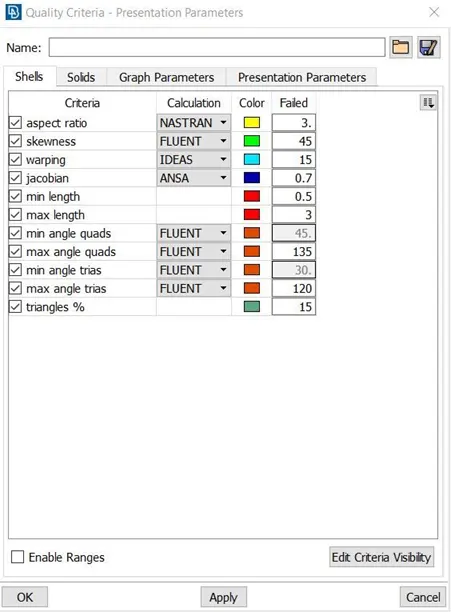
Quality Criteria |
Value |
|
1 |
Target/Average length |
1 |
|
2 |
Minimum Length |
0.5 |
|
3 |
Maximum Length |
3 |
|
4 |
Aspect |
3 |
|
5 |
Warpage |
15 |
|
6 |
Skewness |
45 |
|
7 |
Jacobian |
0.7 |
|
8 |
Minimum Quad Angle |
45 |
|
9 |
Maximum Quad Angle |
135 |
|
10 |
Minimum Tria Angle |
30 |
|
11 |
Maximum Tria Angle |
120 |
|
10 |
Tria Percentage |
15 |
Procedure:
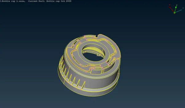
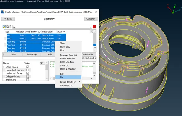
Import the model first. Now check the geometry for any errors like singlecon, needle face, crack surfaces using checks- geometry tool in menubar. after that select execute and select all the errors and right click-fix to fix those errors.
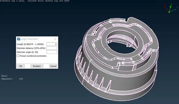
Now select mesh-perimeter-length tool and give 1 as a value to refine the macros and perimeter of the model for good resolution to see the component.
Checking for any errors:
This process is used to check the topology of the model.
In order to check the Topology follow the process as Tools>> Checks >> Geometry>> Execute.
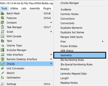
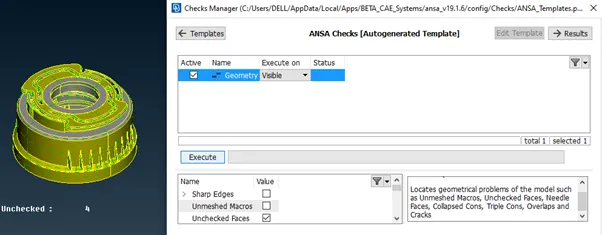
Once executed, it might show a green bar stating there are no errors in the geometry or it may show the dialog box showing the errors present in it.
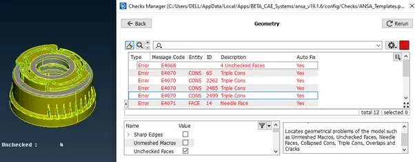
These errors can be fixed either by going on with them individually or once Right-clicked on the mouse an additional list pops- up.
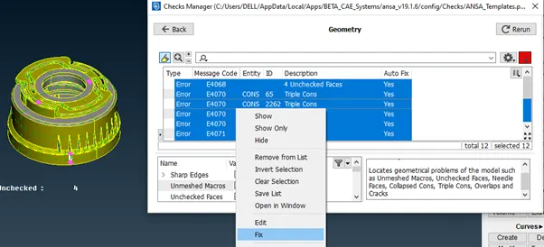
Fix option will be present in that pop-up when it is clicked the errors which can be fixed are executed and it might contain only a few errors that should be fixed manually and if no errors are present then it will show the green bar stating executed.
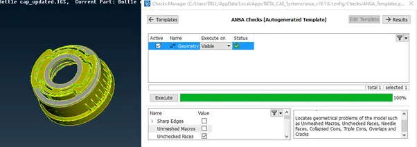
The process is called geometric clean- up. It can be done either completely or part-wise of the parent geometry.
Now use not, or, i-not tools to separate the surfaces for taking midsurfaces.
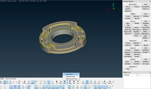
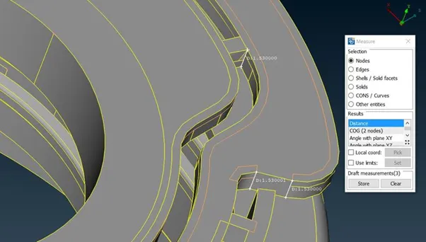
First measure the thickness of the model to get a idea to extract the midsurface for the macros.
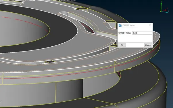
Now the thickness of the two surfaces is same overall we should use offset option topo-faces-offset. assign value as half of the thickness and select the faces to offset. give negative value when the arrow in opposite side. Click ok and click no to delete the surface for further reference.
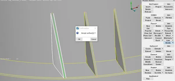
The model has varying thickness in some surfaces. those surfaces are extracted by using middle tool in top module topo- faces-middle- (single or multi). for ribs we can use both, but the surfaces are single. use middle single. now select the first surface then click second surface. now click ok to accept surface. now the midsurface is generated.
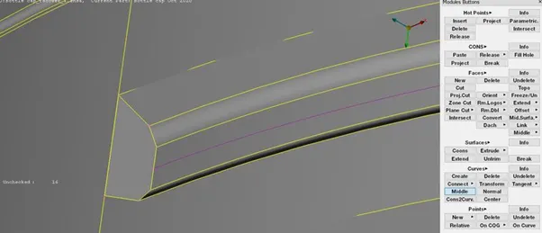
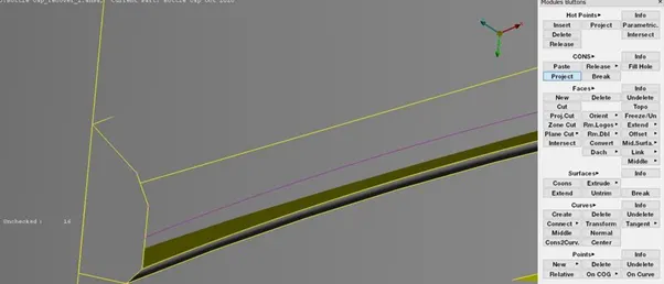
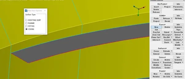
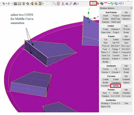
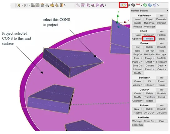
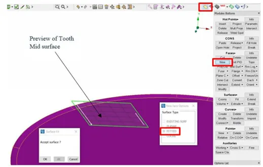
Here we have some threads in the bottle cap. it has trapezium-shaped surface for those surfaces take mid curve to get an exact mid surface topo-curve-middle select the two curves one by one and click ok to get the mid curve. now project the midcurve to mid surface topo-cons-project and now use those curves to create a new surface using topo-faces-new. The midsurface is generated for threads.
How to take Mid surface for all Teeth?
Hint: It is time consuming if the mid surface is extracted one by one for all the teeth of the bottle. So in order to
save time, the Rotate command under the Transform icon is used. (Here,The basic idea is to extract one mid
surface for one tooth & copy that mid surface and then duplicate by required numbers)
Step 1:
In order to create a mid surface for one tooth, Middle option (in Curves) is used to create a middle curve at
the front face of the tooth. (Refer images below)
Step 2:
Use Project option (in Curves), select the line from the back side and Project that line to Base mid surface.
(Refer images below)
Step 3:
Select both the curves and create a Surface, which will be mid surface of a tooth. (Refer image below)
Step 4:
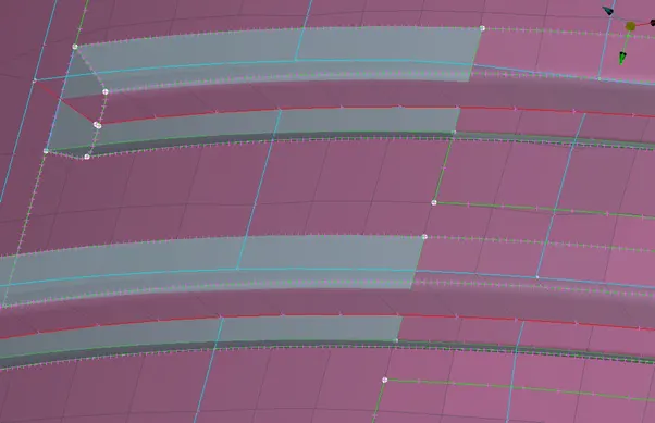
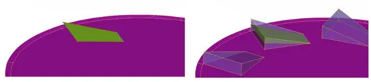
- By this way, Mid surface is created for one tooth. (Refer image below)
Step 5:
In order to use the Rotate option for duplicating this Mid surface of a tooth, Axis of Rotation is required. In
order to create that, We should have at least two center points.
To create a center point, On COG option is used in Points.
Select two circular lines one by one to create points one by one. (Refer image below)
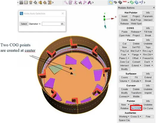
Step 6:
Now, Click on the Transform icon and then click on Copy. Select Entity as the Mid surface of a tooth. (Refer
images below)
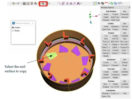
Step 7:
Fill the details as shown in figure below.
- Total no. of threads are 9 and one Tooth mid surface is already done. So, in steps we need to write 8. Which will create 8 more mid surface.
- Click on X box and then select COG point 1. Similarly click on the dX box and then select COG point 2. (By doing this, Axis of rotation will be created)
- Angle between two entities = Total Angle of a circle / Total no. of teeth
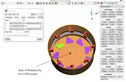
After doing this, we can observe that new mid surfaces (in green colour) will be duplicated successfully.
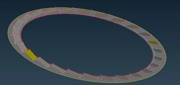
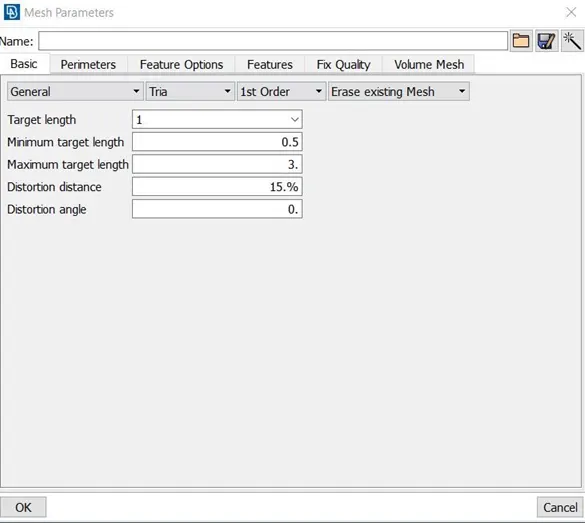
Now we can move to mesh the model. first set the mesh parameters. give target element length as 1mm, min length as 0.5mm, max length as 3mm. select ok.
Now give quality criteria for the mesh. Select quality criteria and assign values as given in the above. select presentation parameters. select elements percentage. Now click ok.
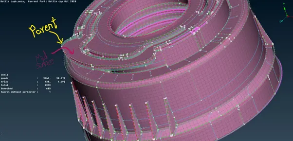
First select the macros and select best mesh in the mesh generation (mesh-mesh generation-best). now the mesh is generated in the selected macros. follow the same procedure for mesh generation. Now use reconstruct tool for remesh the exsiting mesh (mesh-shell mesh-reconstruct).
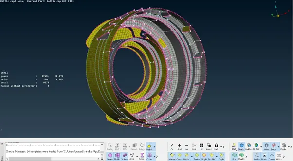
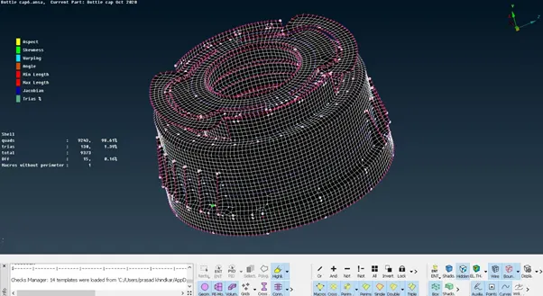
Now use split, paste, swap option for reduce the opposite trias, back to back trias in the exsiting mesh in the model (mesh-element-split/swap) (mesh-grids-paste).
Split- the tool used to split the elements by edges and by nodes and used to move forward the tria.
Paste- the tool used to move the tria to backwards by pasting the nodes.
Swap- the tool used to swap the tria to next element.
Some elements around the triple cons are failed for minimum length, aspect ratio. Those elements are under OFF elements.

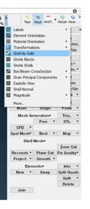
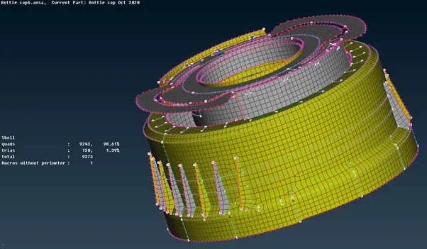
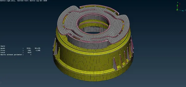
Now select the draw shell as solid tool in presentation parameters tab to see the thickened solid pattern of the mesh.
Final Meshed Component:
Final shell elements represented as solid component:
Learning outcomes:
Learnt to use the different kind of tool to create midsurface, to create a surface using midcurve, to transform the pattern of surface in the model.
Conclusion:
The given bottle cap model is meshed with given quality criteria using midsurface
Model link:
https://drive.google.com/file/d/1z5bNZUJKSwkVfiL9F8zgOcoo3l2jkuMw/view?usp=sharing