3D Creation of Celing, Roof, Architectural plan, Structural plan, Sectional view, Elevation view and Camera specific view for a house plan using REVIT
1) Based on the project saved from Week 3, proceed from the First Floor Level. Model a Ceiling from the architecture tab above the walls at the first-floor level
Aim : To model a ceiling from architecture tab above the walls at the first-floor level for the project saved in week 3 challenge in the Revit software.
Introduction :
- Ceiling is an overhead interior surface that covers the upper limits of a room.
- Ceiling is not generally considered as structural element but a finished surface concealing the underside of the roof structure or floor of story above.
- To model a ceiling, the ceiling tool from architecture tab is used.
Procedure :
Step 1
- Open Revit software, select the challenge 4 file from home page of Revit software to open it.
Step 2
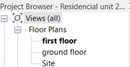
- Double click on the first floor plan view from project browser to open the view as shown below.
Step 3
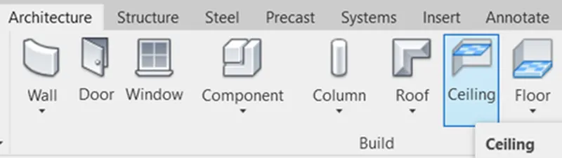
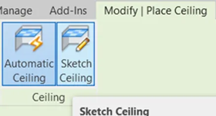
- Go to the architecture tab, select the ceiling tool from build panel, then select the sketch ceiling tool from ceiling panel of modify place ceiling tab.
Step 4
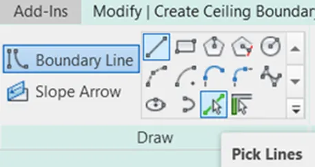
- Select the pick line tool from draw panel of create ceiling boundary tab and select boundary lines to draw the ceiling as shown below and click on the finish mode tool from mode panel.
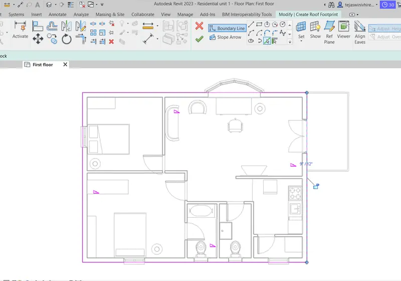
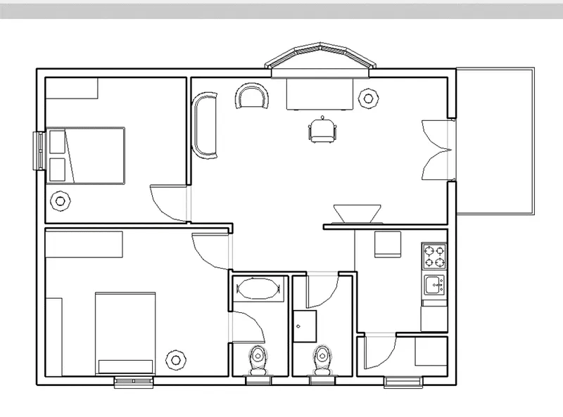
- The first floor plan is as below. Save the file using file menu of top toolbar.
Result :
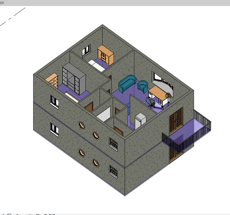
The ceiling is modelled above the walls at the first floor level for the project saved in week 3 and output by following above mentioned procedure in the Revit software is shown below.
First floor plan
3D realistic view of the residential unit.
2) Model a roof above the ceiling by selecting the footprints of the ceiling. Using the adjustment toolbars appearing on-screen adjust the roof slope to 10 degrees.
Aim : To model a roof above ceiling by selecting the footprints of the ceiling and adjust the roof slope to 10 degrees in the Revit software.
Introduction :
- Ceiling is an overhead interior surface that covers the upper limits of a room.
- For modeling the ceiling in the Revit software, the ceiling tool from architecture tab is used and roof is modelled by selecting the footprint of the roof as a line on the top of the wall.
Procedure :
Step 1
- Open the Revit software, open the file saved in previous question.
Step 2
- Go to first floor plan view by double clicking on first floor plan view from project browser window.
Step 3
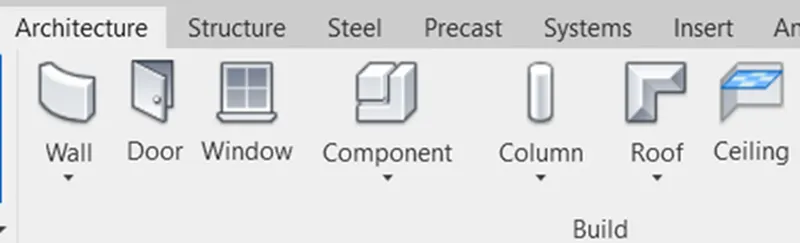
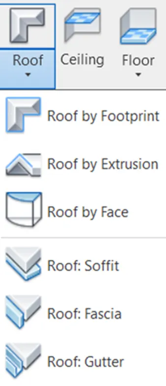
- Go to architecture tab, select the roof tool dropdown from build panel, select the roof by footprint option, make sure base offset from first floor is 10’ in the properties window.
Step 4
- Select the pick line tool from draw panel of create roof footprint tab and select the lines to draw the roof and select attach option from attach to roof window to attach the highlighted walls to roof as shown below.
Step 5
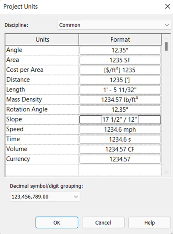
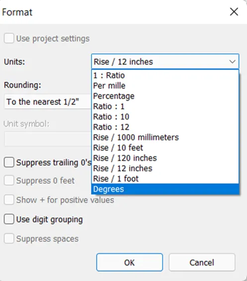
- To change the slope of the roof, make sure unit of angle measurement is degrees for that type UN command it will open the project unit dialog box, select the slope option, select the drop down of unit to change the units to degree and select ok.
Step 6
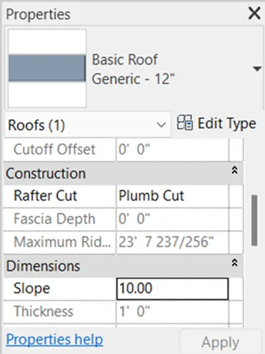
- To change the roof, select the roof, go to the properties window and change the slope to 10 degree and select apply.
Result :
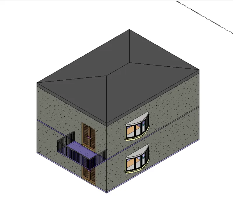
Therefore, the roof above the ceiling is modelled in the Revit software by selecting the footprint of the ceiling and roof slope is adjusted to 10 degrees using above mentioned procedure as shown below.
3D realistic view
3) Using the file saved from weeks 2 to 4, create plan views for ground floor level and first-floor level including all the walls, floors, and components. Separate them to
architecture and structural plans
- Architecture plan must have walls, floors, and all the components placed within the building
b. Structure plan must have details of only walls, floors, and columns
Aim : To create plan views for ground floor level and first floor level and separate them to architecture and structural plans in the Revit software.
Introduction :
- Structural plans primarily concerned with load carrying members of a structure such as beams, columns, walls, stairs etc.
- Architectural plans consists of architectural components such as furniture, architectural components, doors, windows etc.
- In Revit software, the structural plans are created automatically if we model the architectural plan using the structural plan view of the plan view tool of the view tab.
Procedure:
Step 1
- Open the Revit software, select the residential unit file and open it from Revit home page.
Step 2
- To create the architectural plan view, go to the view tab, click on the drop down of plan view, select the floor plan option from the list.
Step 3
- After selecting floor plan view it will open the new floor plan dialog box, select the edit type from it.
- After clicking edit type it will open the type properties dialog box, from this dialog box make sure view template applied to new view is architectural template and select ok it will again open the new plan view dialog box.
- Again, from new floor plan remove the tick mark to create the duplicate view, select the ground floor plan and select ok.
Step 4
The architectural plan view is shown below.
Step 5
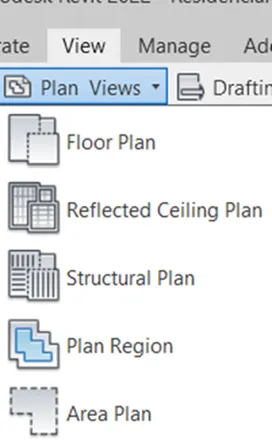
To create the structural plan of the ground floor, again go to view tab, click on the plan view drop down, select the structural plan from the list, it will open the new structural plan dialog box.
Step 6
- Select the edit type option from new structural plan dialog box, make sure view template to applied view is structural framing plan and select ok.
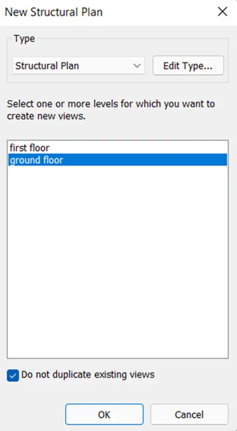
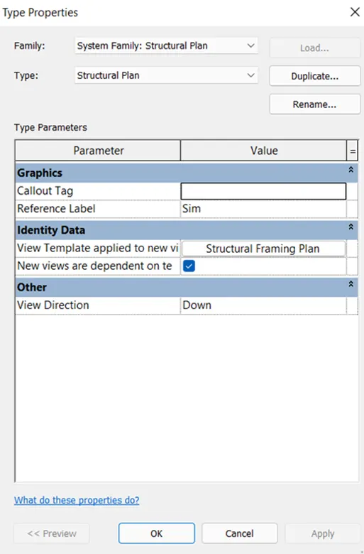
- After selecting ok it will open again the new structural view dialog box, select the ground floor level and select ok.
- The ground floor structural plan view is shown below.
Step 5
- The ground floor structural plan is shown below.
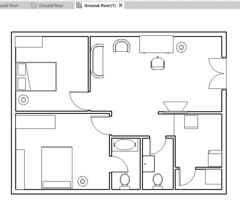
- Similarly create the architectural and structural plan views for first floor plan as shown below and save the file using top toolbar using save icon.
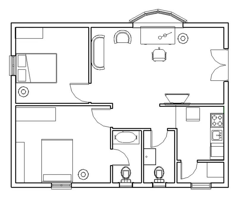
Result :
Therefore Architectural and structural plan views are created for ground and first floor in Revit software by following above mentioned procedure as shown below.
- Ground floor architectural floor plan view
- Ground floor structural plan view
- First floor architectural floor plan view
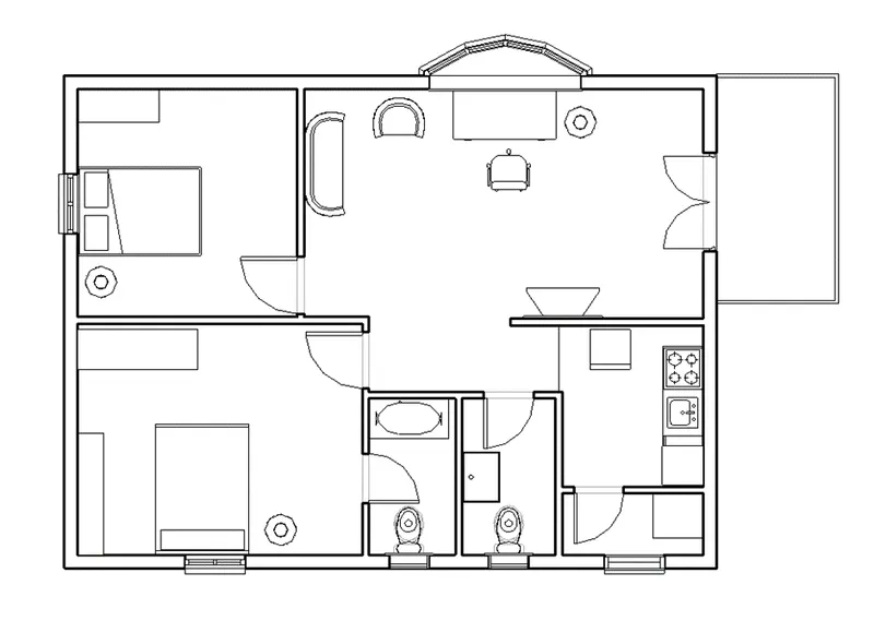
- First floor structural plan view
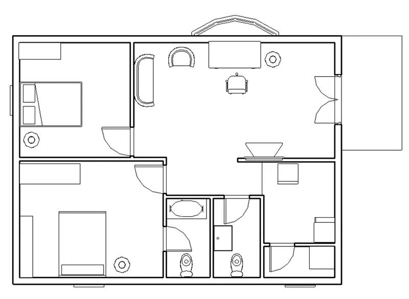
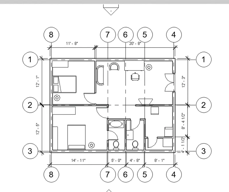
4) Using annotate toolbar add dimensions to all the walls and floors with reference to the longitudinal and transverse grids created in the project file
- The architecture plan dimensions include details on where the components are placed within the buildings with relation to grids. Overall dimensions are sufficient for architecture plans
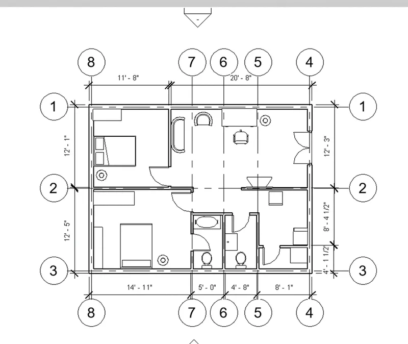
- The Structure plan dimensions must include details on the position of all the walls and interior walls with reference to grids. Locate all the framing components of the building with reference to a fixed point using Structural plans
Aim : To add dimensions to all walls and floors with reference to the longitudinal and transverse grids created in the project.
Introduction :
- Dimensions are added into the architectural and structural plan views using the linear or aligned tool of dimension panel of the annotate tab.
- Dimensions add the details to the plans views which are helpful to locate the components with reference to the grid lines.
Procedure :
Step 1
- Open the Revit software, select the last saved residential unit file from home page of Revit software and open it from home page of Revit.
Step 2
- Double click on the first floor plan from property browser to open the architectural first floor plan.
- Go to the annotate tab, select the linear tool from dimension panel.
Step 3
- Select the first corner point of wall, the select the second corner point of the wall, the move the cursor upward and place dimension line to appropriate position as shown below.
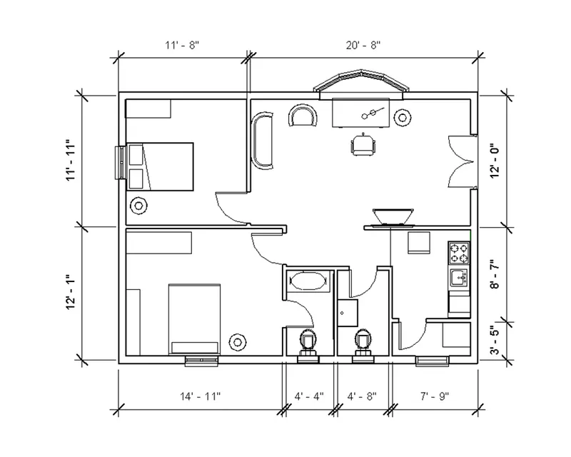
- Similarly give the dimensions to all other walls and floor wherever required as shown below.
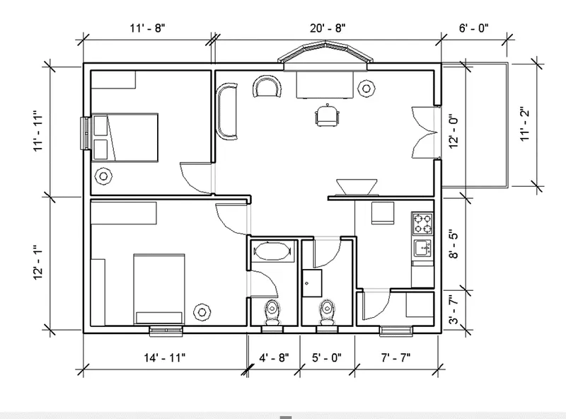
Step 4
- Double click on the first floor structural plan from property browser to open the structural plan view.
Step 5
- Again, go to annotate tab, select the linear option, select first point, select opposite corner point, move cursor in upward direction and place the dimension line at the appropriate position as shown below.
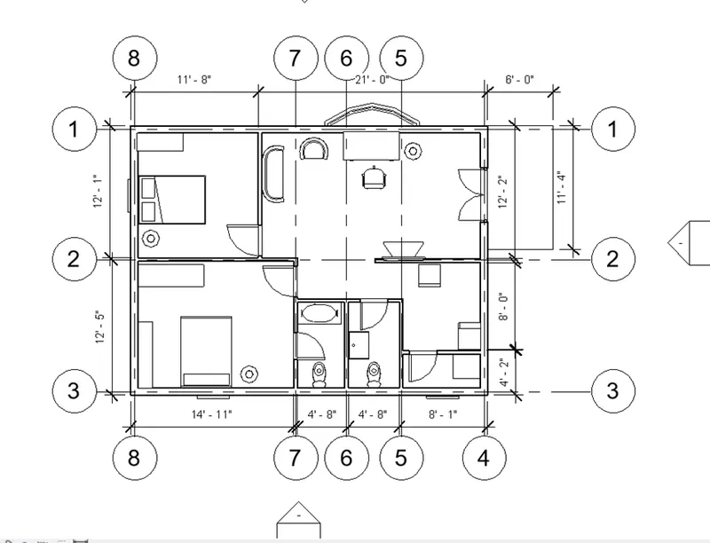
- Similarly, give dimensions to other components using the similar procedure as shown below and save the file using the save icon from top toolbar of Revit window.
Result :
Therefore, dimensions are added to all the walls and floors with reference to the longitudinal and transverse grids in the Revit software by following above mentioned procedure as shown below.
Architectural floor plan
Structural floor plan
5) Create a sheet template from the view tab and adjust the parameters on the sheet to add appropriate views
Aim : To create the sheet template from view tab and adjust the parameters on the sheet to add appropriate views.
Introduction :
- A template is a predesigned spreadsheet that can be used to create new spreadsheets with the same formatting and predefined formulas.
- Sheet template is created using sheet tool of view tab.
Procedure :
Step 1
- Open rivet software, select the residential unit file from Revit homepage to open it.
Step 2
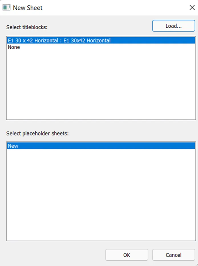
- For creating the sheet, go to view tab, select the sheet tool from sheet composition panel, it will open the new sheet dialog box.
Step 3
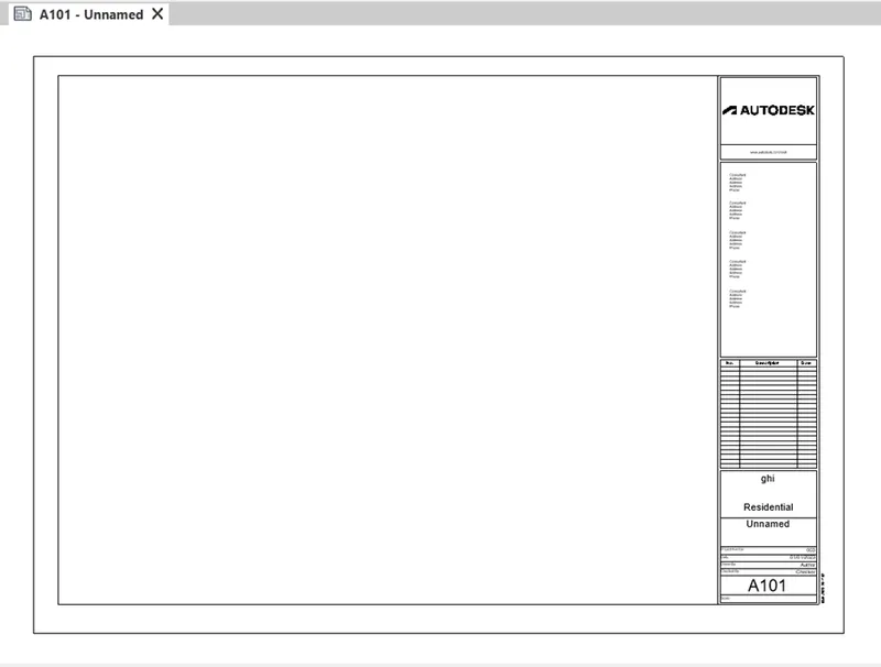
- Select the sheet paper size as E1 30 x 42 Horizontal : E1 30x42 Horizontal and select ok from dialog box, it will open the created sheet template as shown below.
Step 4
- To adjust the parameters on the sheet double click on the parameter and change it as per the required value as shown below.
- Similarly change all the parameters as per desired value as shown below.
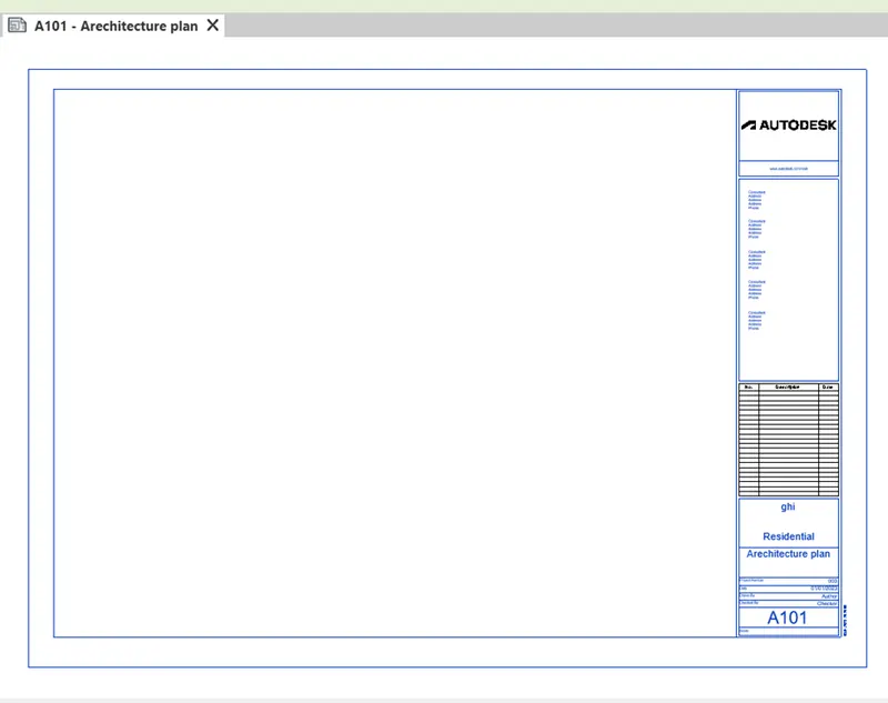
- Similarly change all the parameters as per desired value as shown below.
Step 5
- For cropping the floor plan view, go to architectural ground floor plan by double clicking on ground floor plan view from the project browser.
- Select the show crop region tool from bottom tool bar of the Revit window and adjust the view as shown below.
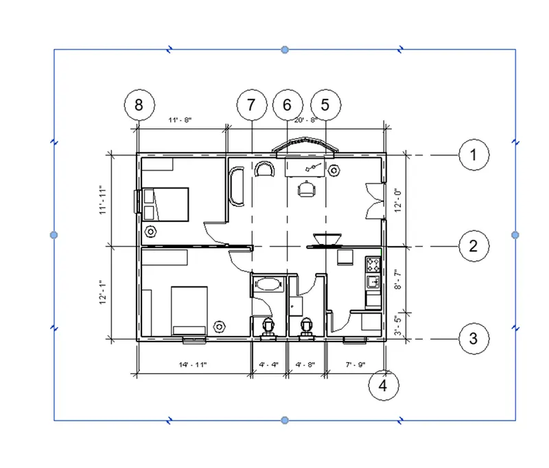
- Again select hide the crop view region tool from bottom toolbar to hide the view region rectangle in the view.
Step 6
- Go into template sheet view by double clicking on the sheet from project browser.
- Now, drag the architectural ground floor plan into sheet with the help of mouse and adjust it in appropriate position.
- Change the scale of the sheet from property window to the scale which properly fits into template sheet as shown below.
- Adjust the view at appropriate position as shown below.
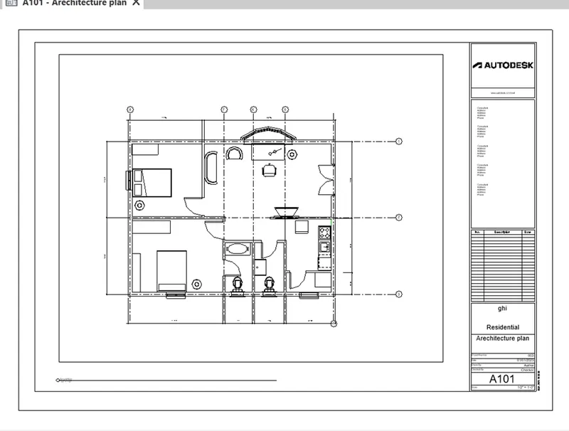
Result :
Therefore a sheet template is created and parameters are adjusted to add the appropriate views in the Revit software by following above mentioned procedure as shown below.
6) Using the elevation tab create the elevation views, looking at your building from East, North, South, and West
Aim : To create the East, North, South and West elevation views of the building using the elevation tab.
Introduction
- Elevation views are created in the Revit software by using the elevation tool of view tab of create panel.
- Elevation views include south, north, east and west view.
Procedure :
Step 1
- Open the Revit software, select the residential unit file from home page of Revit and open it.
Step 2
- Double click on the ground floor plan from project browser and open the view.
Step 3
- Go to the view tab, select the drop down of elevation tool from create panel, select the elevation option from list and place the elevation at desired location at the top of the plan.
- Go to the elevation views from project browser, right click on elevation view and rename it as South.
Step 2
- Again, go to view tab, select the drop down of the elevation tool from create panel and inset the elevation view icon at the right side of plan.
Step 3
- Go to the property browser and rename it as West as shown below.
Step 4
- Again, go to view tab, click on drop down of elevation tool from create panel, select the elevation option and place the elevation icon at down side of the plan.
- Go to the project browser and rename it as North.
Step 5
- Again, go to view tab, click on drop down of elevation tool from create panel, select the elevation option and place the elevation icon at left side of the plan.
- Go to the project browser and rename it as East.
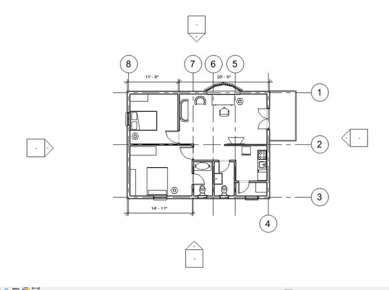
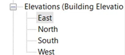
Result :
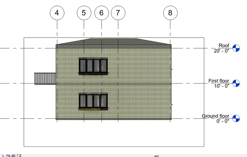
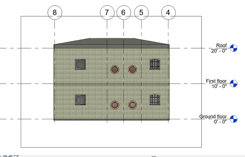
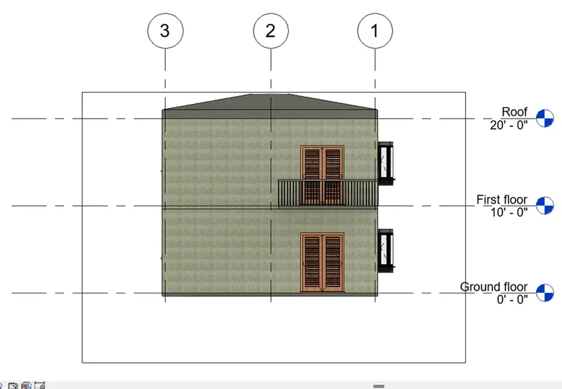
Therefore, the east, north, south and west elevation views are created in Revit software by following the above mentioned procedure as shown below.
East elevation view
North elevation view
South elevation view
West elevation view
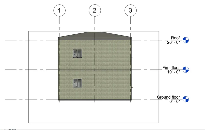
7) Produce section cut through each room either cutting across longitudinally or in a transverse direction
Aim : To produce a section cut through each room either cutting across longitudinally or in transverse direction in Revit software.
Introduction :
- Section views are used in technical drawings to expose internal surfaces.
- They servers to present additional orthographic views of surfaces that appears as hidden lines in the standard front, top, and side orthographic views.
- Section views are added in Revit software by using section tool of view tab.
Procedure :
Step 1
- Open rivet software, select the residential unit file from Revit homepage to open it.
Step 2
- Double click on the ground floor plan from project browser to open the view.
Step 3
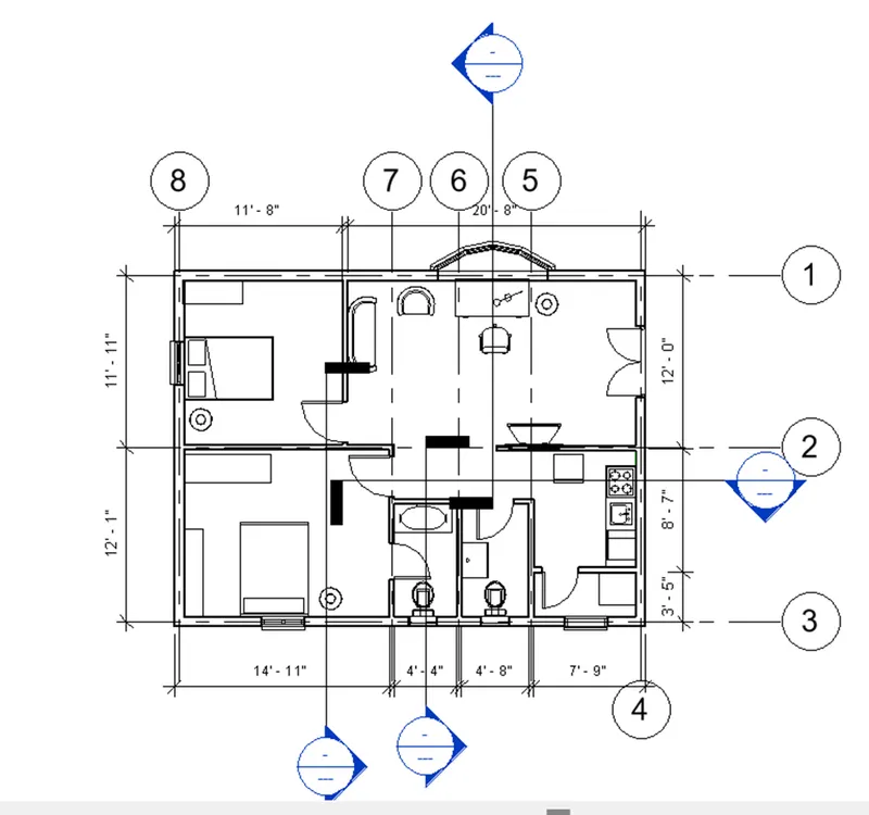
- Go to view tab, select the section tool from create panel, cut the longitudinal section through the living room.
- Go to project browser, select the section view, right click on it and rename it as Living room section.
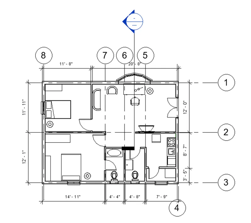
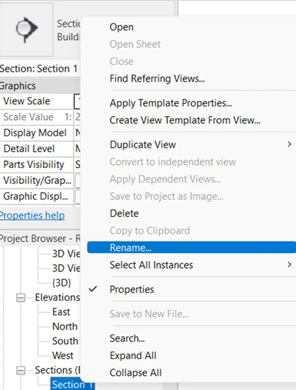
Step 4
- For cutting section through kitchen cum dinning room, again go to view tab, select the section tool, draw the transverse section line through kitchen room as shown below.
- Go to project browser, select the section view, right click on it and rename it as kitchen section.
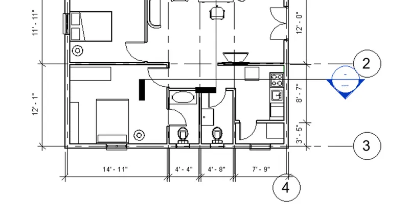
Step 5
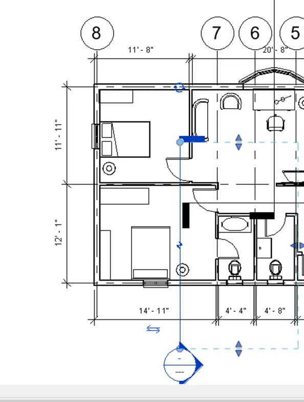
- For creating section view of bedroom, go to view tab, select the section tool from create panel, cut the longitudinal section through the bed room.
- Go to project browser, select the section view, right click on it and rename it as bedroom section view.
Step 6
- For creating section view of bathroom, go to view tab, select the section tool from create panel, cut the longitudinal section through the bathroom.
- Go to project browser, select the section view, right click on it and rename it as bathroom section view.
Result :
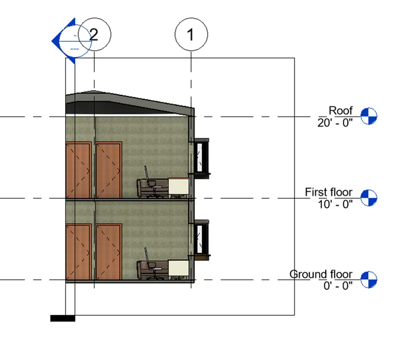
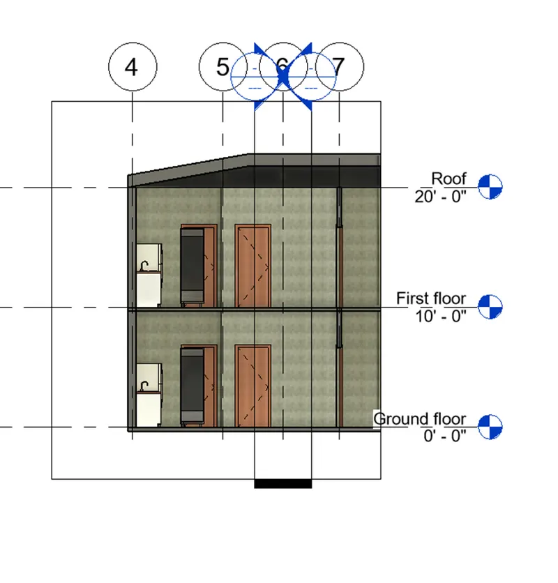
Therefore, the section cuts are produced through each room in longitudinal and transverse direction in Revit software as shown below.
Realistic section view of living room
Realistic section view of kitchen room
Realistic section view of bedroom
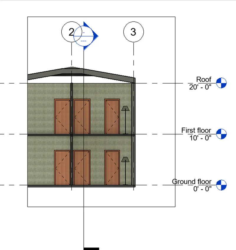
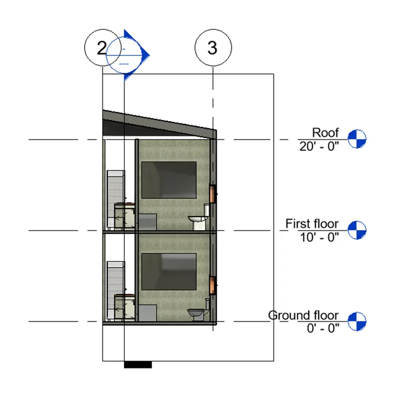
Realistic view of section through toilet room
8) Classify the views, Plan Views, Section Views, and Elevation views to either Design or Documentation category using Properties browser
Aim : To classify the views, plan views, section views and elevation views to either design or documentation category using properties browser in Revit software.
Introduction
- Various views are created in Revit software such as plan view, elevation view, section views, etc, which are helpful to presentation of the details of the project.
- After creating the specific view using the corresponding tool of Revit software, the view is automatically added in the project browser to access the view.
Procedure
Step 1
The views are classified as
- Structural plan views
- Floor plan views
- Ceiling plans
- 3D views
- Elevations
- Sections
- Rendering views
- Area plans
Step 2
Structural plan view
- Structural plan view consist of all the structural components such as structural wall, columns, stairs, floors, beams etc.
- In Revit software structural plan views are created using plan view tool of view tab under the type structural plan view.
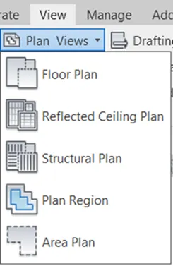
- After creating the structural view, the view is automatically added in the project browser.
Step 3
Floor plan view
- Floor plan view consists of all the Architectural floor plan view which includes all the structural such as walls, columns, floors and architectural components, furniture, doors, windows etc.
- In Revit software floor plan views are created using plan view tool of view tab under the type floor plan.
Step 4
Ceiling plan view
- Ceiling is an overhead interior surface that covers the upper limits of a room.
- Ceiling is not generally considered as structural element but a finished surface concealing the underside of the roof structure or floor of story above.
- To model a ceiling, the ceiling tool from architecture tab is used.
Step 5
3D views
- 3D views are virtual representation of building which helps to predict the futural realistic view of the buildings.
- 3D views in the Revit software are created by placing the camera at appropriate position to get the camera specific views.
Step 6
Elevations
- Elevation views are the view of the building seen from one side such as north, south, east or west side.
- Elevation views are created using the elevation tool of the view tab from create panel and can be obtained from project browser.
Step 7
Sections
- Section views are used in technical drawings to expose internal surfaces.
- They servers to present additional orthographic views of surfaces that appears as hidden lines in the standard front, top, and side orthographic views.
- Section views are added in Revit software by using section tool of view tab and can be seen using the project browser.
Step 8
Rendering views
- Rendering views are views that are added in the list if we render camera specific view and save the view in the project.
- Rendered views are the more realistic views of the building which are created using render tool from view tab from the presentation panel.
Step 9
Area plans
- Area plans are the plans that only represent the area of the building.
- Area plans are created using the plan view tool of the create panel of the view tab and added in project browser automatically after creating view.
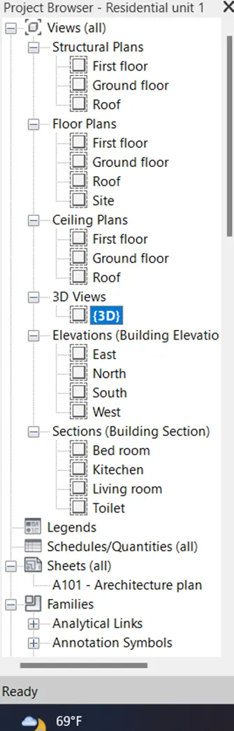
Various views classified in the Revit software are specified in the project browser as shown below.
Result :
Therefore, various views such as plan views, elevation views, section views which can be created in Revit software are classified above and added can be shown on the project browser as shown below.
9) Using the sheet template produced create multiple sheets as follows
a. A 101- Ground Floor Architecture Plan
b. A 102- First Floor Architecture Plan
c. A 103- Roof Plan
d. S 101- Ground Floor Structural Plan
e. S 102- First Floor Structural Plan
f. S 103- Roof Framing Plan
g. A-201- North-South Elevations
h. A-202- East-West Elevations
Add additional sheets based on the sections created in your Revit file
Aim : To create multiple sheets using sheet template and add different views in Revit software.
Introduction
- A template is a predesigned spreadsheet that can be used to create new spreadsheets with the same formatting and predefined formulas.
- Sheet template is created using sheet tool of view tab.
- Various views are added in the sheets by dragging the view from project browser using the mouse.
Procedure
Step 1
- Open rivet software, select the residential unit file from Revit homepage to open it.
Step 2
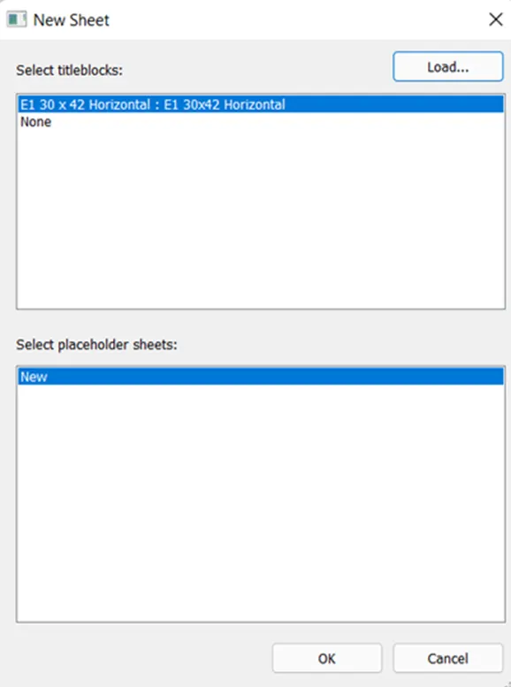
- For creating the sheet, go to view tab, select the sheet tool from sheet composition panel, it will open the new sheet dialog box.

Step 3
- Select the sheet paper size as E1 30 x 42 Horizontal : E1 30x42 Horizontal and select ok from dialog box, it will open the created sheet template as shown below.
Step 4
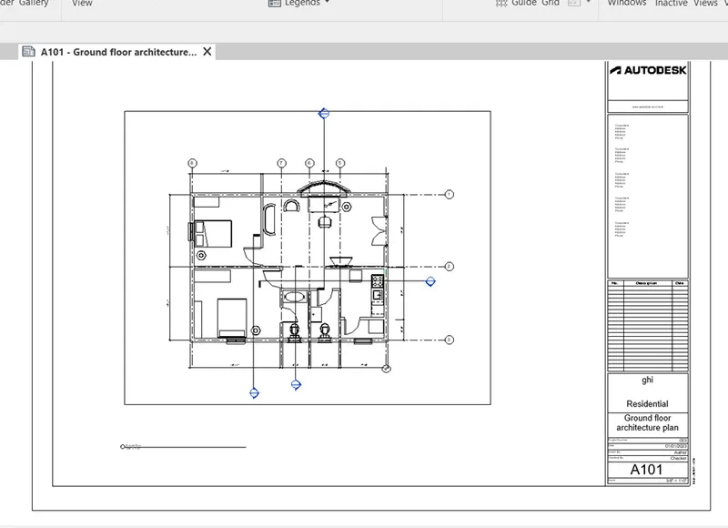
- To change the name of sheet double click on name and change it as A 101.
- Similarly double click on the sheet number and change it as A101 as shown below.
Step 5
- Select the architectural ground floor plan view from project browser and drag the view in the sheet using mouse.
- Change the scale of the view using property window to fit the view into the sheet as shown below.
Step 6
- Again go to view tab, select the sheet tool, and add the sheet as explained above.
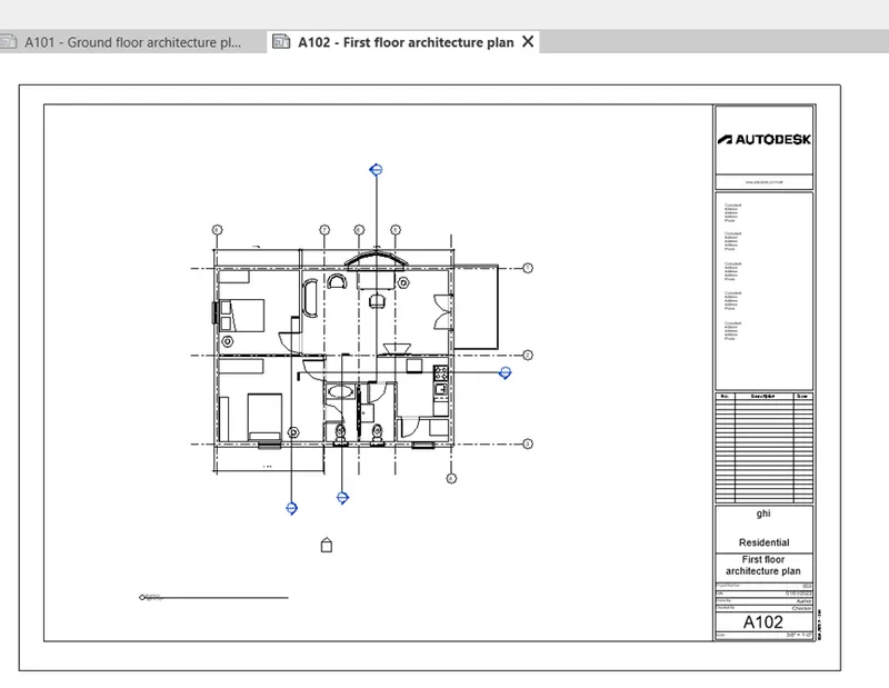
- To change the name of the sheet double click on the name and edit it as A 102
- Go to the property browser, select the architectural first floor plan view, drag the view into the sheet, change the scale of the view such that the view fits into sheet from the property window as shown below.
Step 7 : roof plan
- Again go to view tab, select the sheet tool, and add the sheet as explained above.
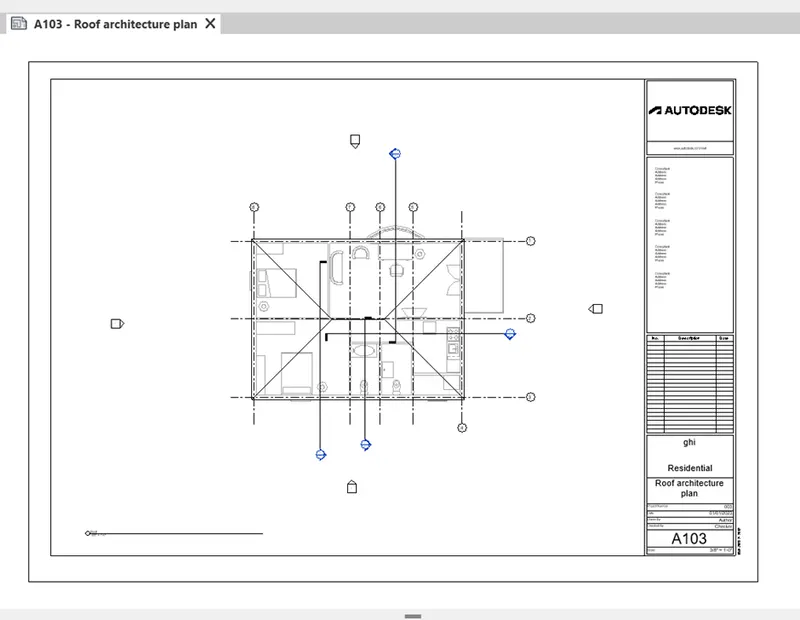
- To change the name of the sheet double click on the name and edit it as A 103
- Go to the property browser, select the architectural roof framing plan view, drag the view into the sheet, change the scale of the view such that the view fits into sheet from the property window as shown below.
Step 8
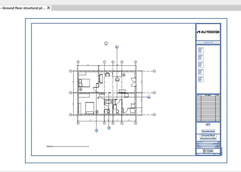
- Similarly add the sheet as explained above using the sheet tool from view tab and edit the name of sheet as S 101.
- Go to the property browser, select the ground floor structural plan view, drag the view into the sheet, change the scale of the view such that the view fits into sheet from the property window as shown below.
Step 9
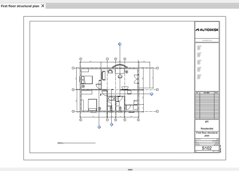
- Similarly add the sheet as explained above using the sheet tool from view tab and edit the name of sheet as S 102.
- Go to the property browser, select the first floor structural plan view, drag the view into the sheet, change the scale of the view such that the view fits into sheet from the property window as shown below.
Step 10
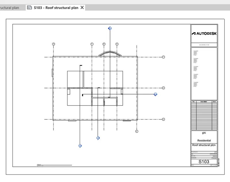
- Similarly add the sheet as explained above using the sheet tool from view tab and edit the name of sheet as S 103.
- Go to the property browser, select the roof framing structural plan view, drag the view into the sheet, change the scale of the view such that the view fits into sheet from the property window as shown below.
Step 11
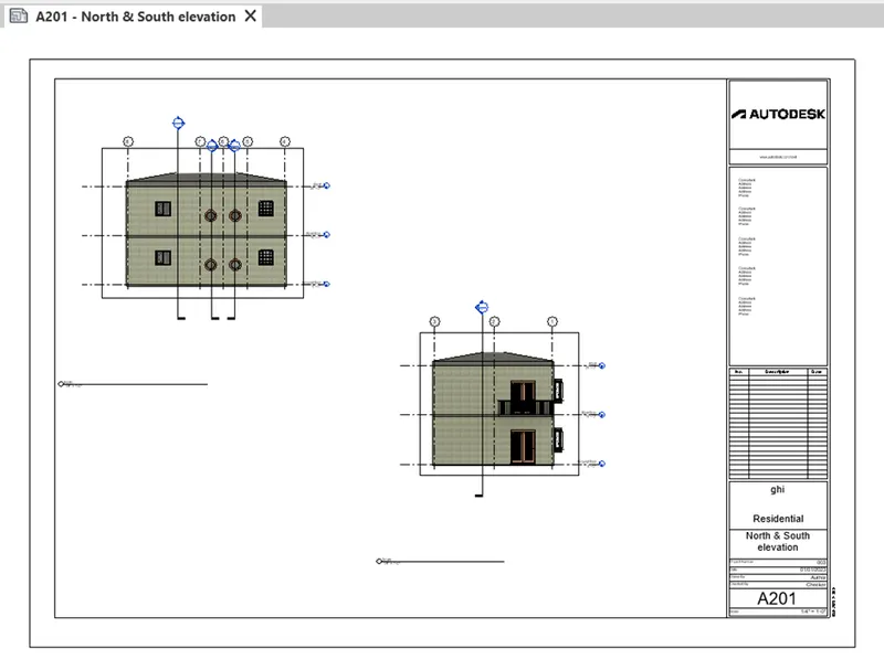
- Similarly add the sheet as explained above using the sheet tool from view tab and edit the name of sheet as A-201.
- Go to the property browser, select the north elevation view, drag the view into the sheet, change the scale of the view such that the view fits into sheet from the property window as shown below.
- Similarly add the south elevation view in the same sheet by dragging it from project browser as shown below.
Step 12
- Similarly add the sheet as explained above using the sheet tool from view tab and edit the name of sheet as A-201.
- Go to the property browser, select the north elevation view, drag the view into the sheet, change the scale of the view such that the view fits into sheet from the property window as shown below.
- Similarly add the south elevation view in the same sheet by dragging it from project browser as shown below.
Step 13
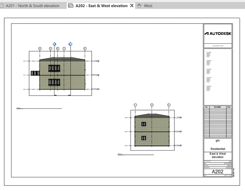
- Similarly add the sheet as explained above using the sheet tool from view tab and edit the name of sheet as A-202.
- Go to the property browser, select the east elevation view, drag the view into the sheet, change the scale of the view such that the view fits into sheet from the property window as shown below.
- Similarly add the west elevation view in the same sheet by dragging it from project browser as shown below.
Step 14
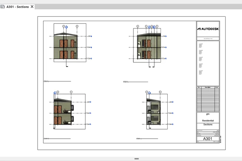
Similarly add the section view in the sheet naming as A-203 as shown below.
Result :
Therefore sheets are created and renamed with the required name in Revit software as shown below.
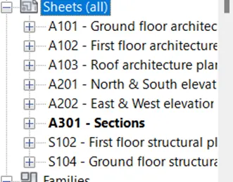
A 101- Ground Floor Architecture Plan
A 102- First Floor Architecture Plan
A 103- Roof Plan
S 101- Ground Floor Structural Plan
S 102- First Floor Structural Plan
S 103- Roof Framing Plan
A-201- North-South Elevations
A-202- East-West Elevations
Additional section view sheet
10) Create a camera-specific view or a 3D view in each room ( living, dining, bedroom). Based on the views create a new set of sheets starting A-501 (you can add as many sheets after, 502, 503.. n)to place the 3D view images. Produce the sheets as a part of project drafting.
Aim : To create a camera specific view or 3D view in each room and set the sheets staring from A-501 as a pert of project drafting in Revit software.
Introduction
- 3D views are virtual representation of building which helps to predict the futural realistic view of the buildings.
- 3D views in the Revit software are created by placing the camera at appropriate position to get the camera specific views
Procedure
Step 1
- Open rivet software, select the residential unit file from Revit homepage to open it.
Step 2
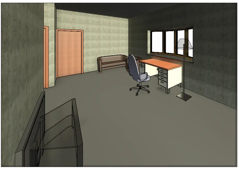
- Go to the view tab, select the 3D view drop down and select default 3D camera from list.
- Open the floor plan view and place the camera at appropriate position.
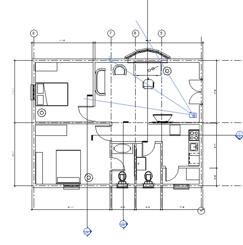
- Go to the realistic view from bottom toolbar to see the realistic view as shown below.
Step 3
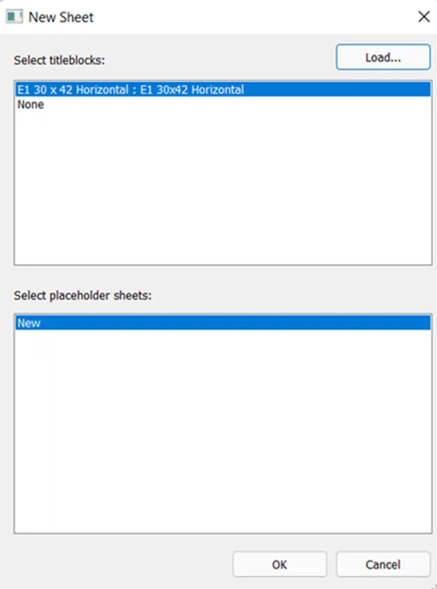
- For creating the sheet, go to view tab, select the sheet tool from sheet composition panel, it will open the new sheet dialog box.
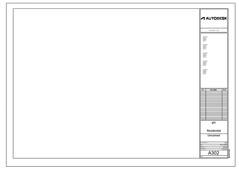
- Select the sheet paper size as E1 30 x 42 Horizontal : E1 30x42 Horizontal and select ok from dialog box, it will open the created sheet template as shown below.
Step 4
- Rename the sheet as A-501 by double clicking on it.
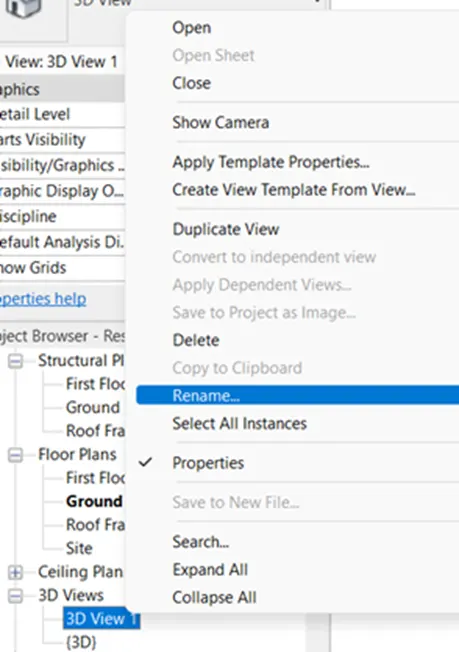
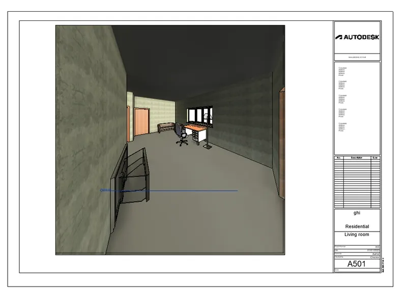
- Go to the project browser right click on created 3D camera view and rename it as Living room.
- Select the 3D view of living room and drag it into the sheet.
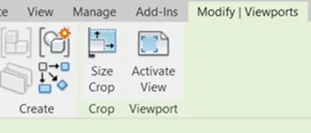
- For changing the size of the view, select the crop size tool from crop panel and change the size such that view fits appropriately into the sheet as shown below.
Step 5
- Go to the view tab, select the 3D view drop down and select default 3D camera from list.
- Open the floor plan view and place the camera at appropriate position.
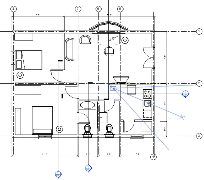
- Go to the realistic view from bottom toolbar to see the realistic view as shown below.
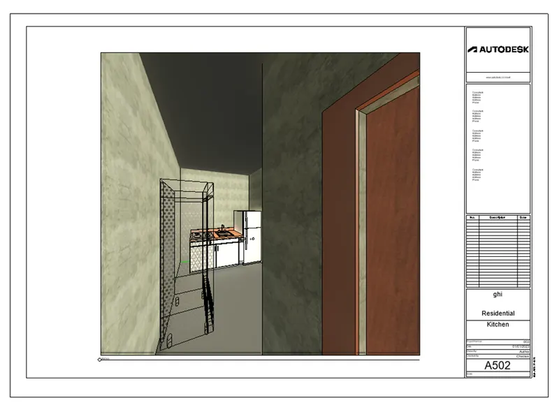
Add the sheet using sheet tool of view tab, and rename it by double clicking on it as A-502.
- Go to project browser and rename the view as Kitchen, select the view and drag the view into the sheet.
- Change the size of the view into the sheet using crop size tool from modify viewport tab such that it fit int the sheet as shown below.
Step 5
- Go to the view tab, select the 3D view drop down and select default 3D camera from list.
- Open the floor plan view and place the camera at appropriate position.

- Go to the realistic view from bottom toolbar to see the realistic view as shown below.
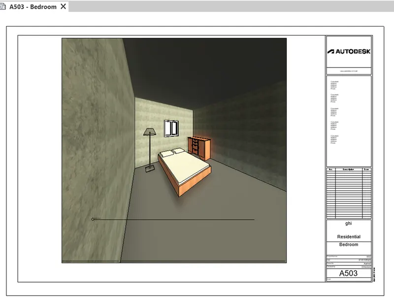
Add the sheet using sheet tool of view tab, and rename it by double clicking on it as A-503.
- Go to project browser and rename the view as Bedroom, select the view and drag the view into the sheet.
- Change the size of the view into the sheet using crop size tool from modify viewport tab such that it fit int the sheet as shown below
Step 6
- Go to the view tab, select the 3D view drop down and select default 3D camera from list.
- Open the floor plan view and place the camera at appropriate position.
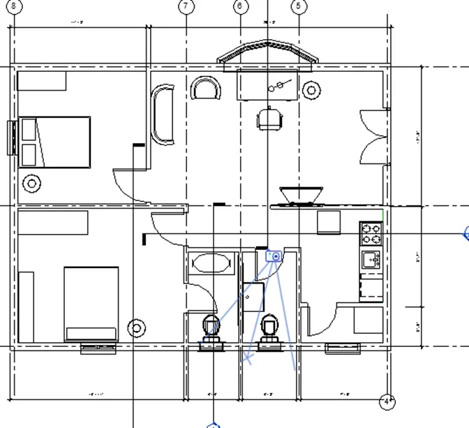
- Go to the realistic view from bottom toolbar to see the realistic view as shown below.
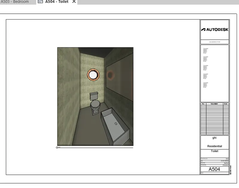
Add the sheet using sheet tool of view tab, and rename it by double clicking on it as A-504.
- Go to project browser and rename the view as Kitchen, select the view and drag the view into the sheet.
- Change the size of the view into the sheet using crop size tool from modify viewport tab such that it fit int the sheet as shown below.
Step 7
- Go to the view tab, select the 3D view drop down and select default 3D camera from list.
- Open the floor plan view and place the camera at appropriate position.
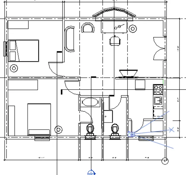
- Go to the realistic view from bottom toolbar to see the realistic view as shown below.
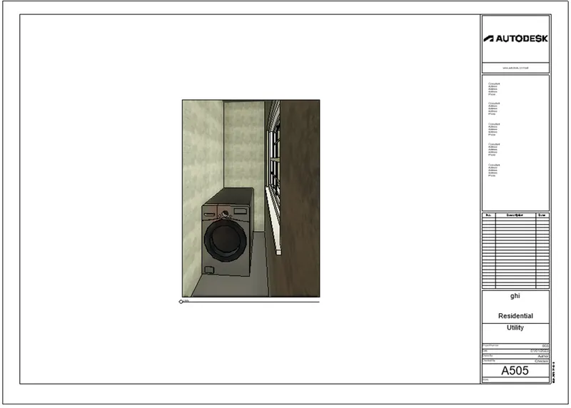
- Add the sheet using sheet tool of view tab, and rename it by double clicking on it as A-505.
- Go to project browser and rename the view as Wash area, select the view and drag the view into the sheet.
- Change the size of the view into the sheet using crop size tool from modify viewport tab such that it fit int the sheet as shown below.
Result :
Therefore, camera specific 3D view in each room are created and set as a sheet starting from A-501 as a part of project drafting in Revit software by using above mentioned procedure as shown below.
Sheet of camera specific realistic view of living room
Sheet of camera realistic view of kitchen room
Sheet of camera realistic view of bedroom
Sheet of camera realistic view of Toilet
Sheet of camera realistic view of Utility