3D Creation of Celing, Roof, Architectural plan, Structural plan, Sectional view, Elevation view and Camera specific view for a house plan using REVIT
3D CREATION OF CEILING, ROOF, ARCHITECTURAL PLAN, STRUCTURAL PLAN, SECTIONAL VIEW, ELEVATION VIEW, AND CAMERA-SPECIFIC VIEW FOR A HOUSE PLAN USING REVIT
TASK 1) Based on the project saved from Week 3, proceed from the First Floor Level. Model a Ceiling from the architecture tab above the walls at the first-floor level
AIM -
- TO STUDY THE CREATION OF 3D CEILING, ROOF, ARCHITECTURAL PLAN, STRUCTURAL PLAN, SECTIONAL VIEW, ELEVATION VIEW, AND CAMERA-SPECIFIC VIEW FOR A HOUSE PLAN USING REVIT
INTRODUCTION -
Autodesk Revit is a building information modeling software tool for architects, landscape architects, structural engineers, mechanical, electrical, and plumbing (MEP) engineers, designers, and contractors. The original software was developed by Charles River Software, founded in 1997, renamed Revit Technology Corporation in 2000, and acquired by Autodesk in 2002. The software allows users to design a building and structure and its components in 3D, annotate the model with 2D drafting elements, and access building information from the building model's database. Revit is 4D building information modeling capable with tools to plan and track various stages in the building's lifecycle, from concept to construction and later maintenance and/or demolition
Tools and their function -
- Navigation - we can use the mouse wheel, Project Browser, or View Cube to open a view and navigate to different areas of the model.
- The Project Browser - Located on the lower left of your Revit screen, the Project Browser acts as a table of contents for your project. Use it to navigate and open views of the model. You can organize, sort, filter, and customize the Project Browser to support your workflow.
- The Properties - The Properties palette lets you view and modify parameters for selected elements. If no element is selected, it displays the properties of the current view. The palette appears by default to the left of the drawing area above the Project Browser.
- Temporary Dimensions - As you create or select geometry, Revit displays temporary dimensions around the element. You can use temporary dimensions to dynamically control the placement of elements. Learn more about Temporary Dimensions
- Levels – Levels are finite horizontal planes that act as references for level-hosted elements, such as roofs, floors, and ceilings.
- WALL - Use a Wall tool to create a non-bearing or structural wall in the building model. Like other basic elements in a building model, walls are instances of predefined system family types, which represent standard varieties of wall function, composition, and thickness
PROCEDURE -
STEP 1
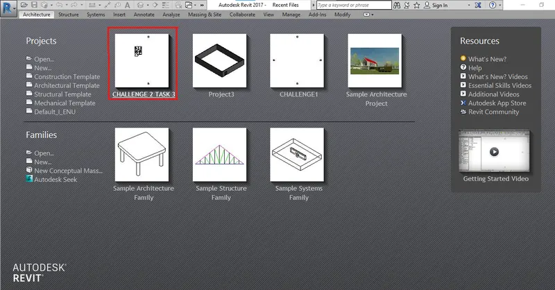
- Go to the Window search box to open a Revit workspace.
- In the window search bar type REVIT, and the icon of the Revit application will show on the screen
- Click on the icon of REVIT, the application of Revit will open and the user interface of Revit will show on the screen.
- Click on the existing project created in week 2 challenges [ project shown in the red box in the picture].
STEP 2
- The existing project will open
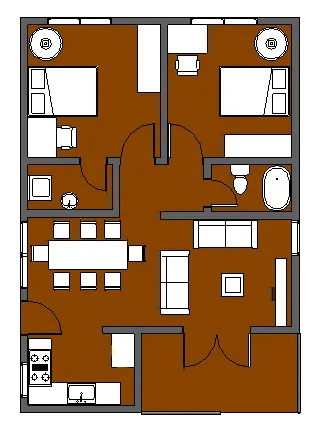
- Click on FLOOR PLAN to see the layout of an existing project.
STEP 3
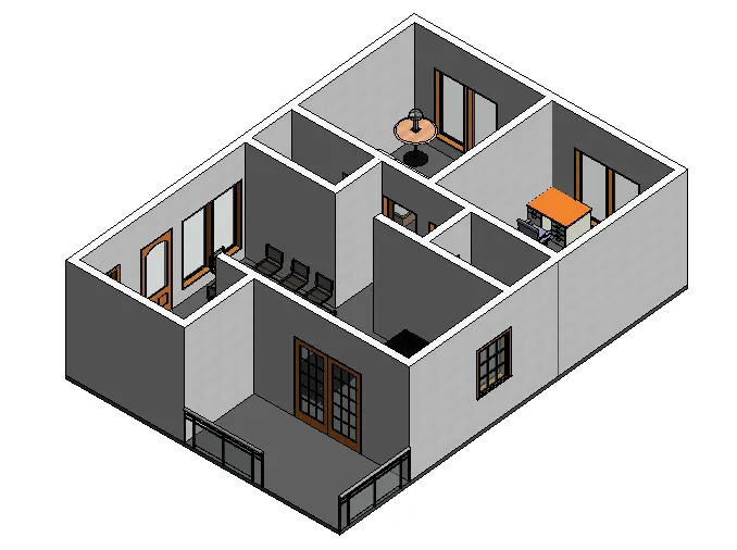
- Click on 3D view to see the building in all directions.
STEP 4
- In the task they specify the location of the ceiling as the first floor. So, we need to create one more level above the ground level
- Go to the floor plan view and select all the components of the building and click on copy to clipboard option and paste to Aligned to select the Level as the first floor.
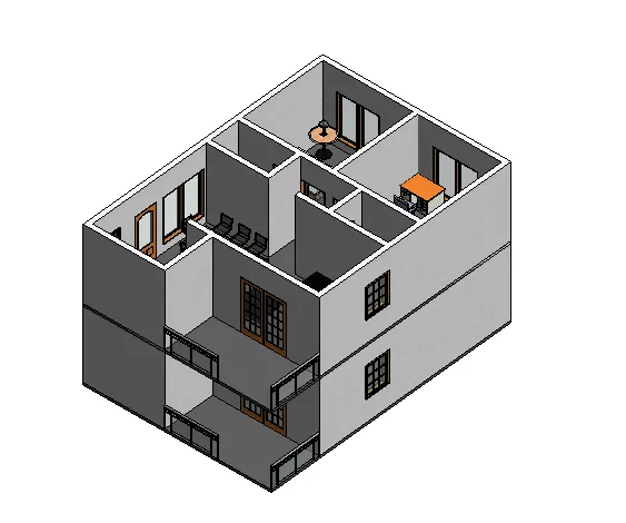
STEP 5
- Go to Ribbon > Architecture > Ceiling for creating the ceiling on the first floor.
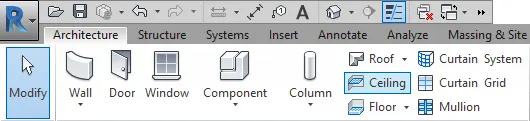
STEP 6
- A new dialog box will open click on the PICK LINE option
- And select the outer line of the wall as shown in the picture.
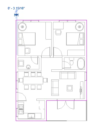
STEP 7
- Press ENTER ceiling is created on the first floor as shown in the picture.
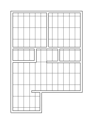
RESULT -
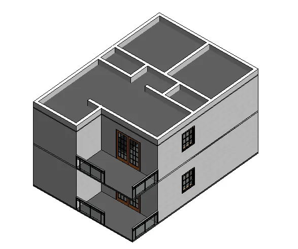
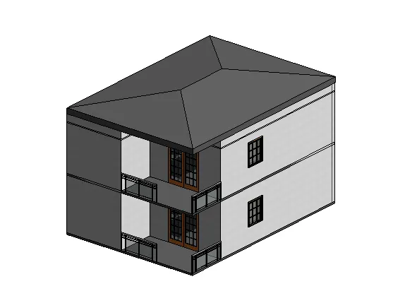
TASK 2) Model a roof above the ceiling by selecting the footprints of the ceiling. Using the adjustment toolbars appearing on-screen adjust the roof slope to 10 degrees
AIM -
- TO STUDY THE CREATION OF 3D CEILING, ROOF, ARCHITECTURAL PLAN, STRUCTURAL PLAN, SECTIONAL VIEW, ELEVATION VIEW, AND CAMERA CAMERA-SPECIFIC OR AHOUSEE PLAN USING REVIT
INTRODUCTION -
Autodesk Revit is a building information modeling software tool for architects, landscape architects, structural engineers, mechanical, electrical, and plumbing (MEP) engineers, designers, and contractors. The original software was developed by Charles River Software, founded in 1997, renamed Revit Technology Corporation in 2000, and acquired by Autodesk in 2002. The software allows users to design a building and structure and its components in 3D, annotate the model with 2D drafting elements, and access building information from the building model's database. Revit is 4D building information modeling capable with tools to plan and track various stages in the building's lifecycle, from concept to construction and later maintenance and/or demolition
Tools and their function -
- Navigation - we can use the mouse wheel, Project Browser, or View Cube to open a view and navigate to different areas of the model.
- The Project Browser - Located on the lower left of your Revit screen, the Project Browser acts as a table of contents for your project. Use it to navigate and open views of the model. You can organize, sort, filter, and customize the Project Browser to support your workflow.
- The Properties - The Properties palette lets you view and modify parameters for selected elements. If no element is selected, it displays the properties of the current view. The palette appears by default to the left of the drawing area above the Project Browser.
- Temporary Dimensions - As you create or select geometry, Revit displays temporary dimensions around the element. You can use temporary dimensions to dynamically control the placement of elements. Learn more about Temporary Dimensions
- Levels – Levels are finite horizontal planes that act as references for level-hosted elements, such as roofs, floors, and ceilings.
- WALL - Use a Wall tool to create a non-bearing wall or real wall in the building model. Like other basic elements in a building model, walls are instances of predefined system family types, which represent standard varieties of wall function, composition, and thickness
PROCEDURE -
STEP 1
- Go to Ribbon > Architecture > Roof > Roof by Footprint for creating the roof on the first floor.
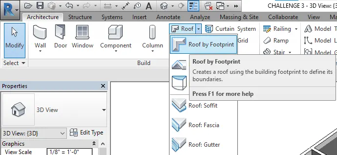
STEP 2
- A new dialog box will open click on the RECTANGLE option
- And Create a region to create a roof as shown in the picture.
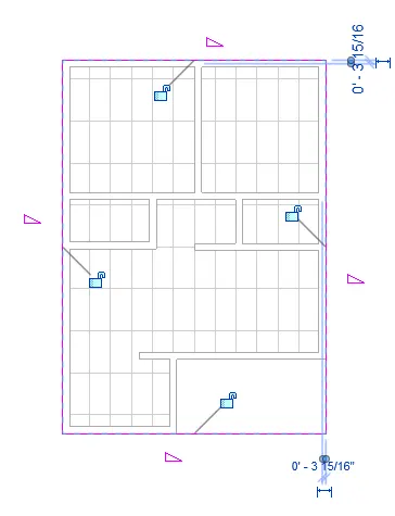
STEP 3
- The roof is now created click on the 3d view to see the roof in 3D
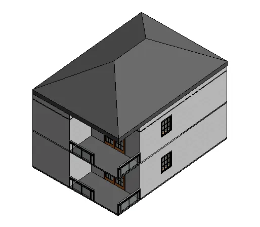
STEP 4
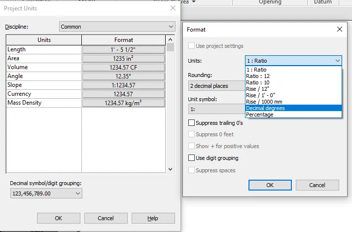
- Type UN to open the project units dialog box
- Click on the Slope format section
- Again a new dialog box will open name as FORMAT
- Click on the UNIT drop-down list and select a decimal degree.
STEP 5
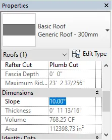
- Select the roof and go to the properties
- Scroll down you will find the box of slope
- Change the dimension of the slope to 10 degrees.
RESULT -
TASK 3) Using the file saved from weeks 2 to 4, create plan views for ground floor level and first-floor level including all the walls, floors, and components. Separate them tintoarfrom architecture and structural plans
a. Architecture plan must have walls, floors, and all the components placed within the building
b. The structure plan must have details of only walls, floors, and columns
AIM -
- TO STUDY THE CREATION OF 3CEILINGNG, ROOF, ARCHITECTURAL PLAN, STRUCTURAL PLAN, SECTIONAL VIEW, ELEVATION VIEW, AND CAMERA-SPECIFIC VIEW FOR A HOUSE PLAN USING REVIT
INTRODUCTION -
Autodesk Revit is a building information modeling software tool for architects, landscape architects, structural engineers, mechanical, electrical, and plumbing (MEP) engineers, designers, and contractors. The original software was developed by Charles River Software, founded in 1997, renamed Revit Technology Corporation in 2000, and acquired by Autodesk in 2002. The software allows users to design a building and structure and its components in 3D, annotate the model with 2D drafting elements, and access building information from the building model's database. Revit is 4D building information modeling capable with tools to plan and track various stages in the building's lifecycle, from concept to construction and later maintenance and/or demolition
Tools and their function -
- Navigation - we can use the mouse wheel, Project Browser, or View Cube to open a view and navigate to different areas of the model.
- The Project Browser - Located on the lower left of your Revit screen, the Project Browser acts as a table of contents for your project. Use it to navigate and open views of the model. You can organize, sort, filter, and customize the Project Browser to support your workflow.
- The Properties - The Properties palette lets you view and modify parameters for selected elements. If no element is selected, it displays the properties of the current view. The palette appears by default to the left of the drawing area above the Project Browser.
- Temporary Dimensions - As you create or select geometry, Revit displays temporary dimensions around the element. You can use temporary dimensions to dynamically control the placement of elements. Learn more about Temporary Dimensions
- Levels – Levels are finite horizontal planes that act as references for level-hosted elements, such as roofs, floors, and ceilings.
- WALL - Use a Wall tool to create a non-bearing wall or a structural wall in the building model. Like other basic elements in a building model, walls are instances of predefined system family types, which represent standard varieties of wall function, composition, and thickness
PROCEDURE -
STEP 1
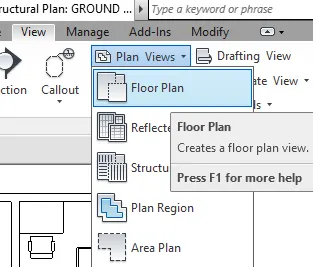
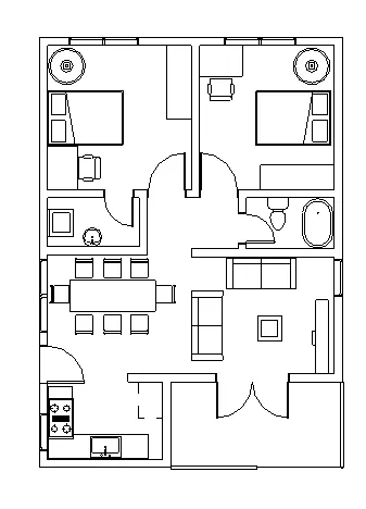
- Go to Ribbon > View > Plan View > Floor Plan for the opening of architecture separately.
STEP 2
- A new dialog box will open select the ground level plan and click on Ok.
STEP 3
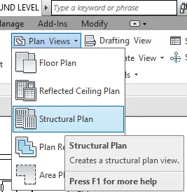
- Go to Ribbon > View > Plan View > Structural Plan for the opening of the structural plan separately.
STEP 4
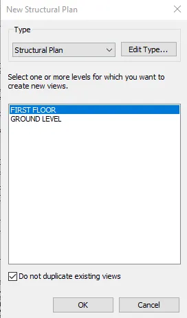
- A new dialog box will open select the ground level plan and click on Ok.
STEP 5
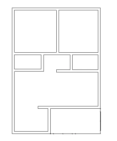
- Structural plan of the ground floor is created
- In the plan we can see only the wall as in structure component we just add a wall elements
TASK 4) Using annotate toolbar add dimensions to all the walls and floors concerning the longitudinal and transverse grids created in the project file
a. The architecture plan dimensions include details on where the components are placed within the buildings and about grids. Overall dimensions are sufficient for architecture plans
b. The Structure plan dimensions must include details on the position of all the walls and interior walls concerning grids. Locate all the framing components of the building by reconceconcerningusing Structural plans
AIM -
- TO STUDY THE CREATION OF 3D CEILING, ROOF, ARCHITECTURAL PLAN, STRUCTURAL PLAN, SECTIONAL VIEW, ELEVATION VIEW, AND CAMERA CAMERA-SPECIFIC OR A HOUSE PLAN USING REVIT
INTRODUCTION -
Autodesk Revit is a building information modeling software tool for architects, landscape architects, structural engineers, mechanical, electrical, and plumbing (MEP) engineers, designers, and contractors. The original software was developed by Charles River Software, founded in 1997, renamed Revit Technology Corporation in 2000, and acquired by Autodesk in 2002. The software allows users to design a building and structure and its components in 3D, annotate the model with 2D drafting elements, and access building information from the building model's database. Revit is 4D building information modeling capable with tools to plan and track various stages in the building's lifecycle, from concept to construction and later maintenance and/or demolition
Tools and their function -
- Navigation - we can use the mouse wheel, Project Browser, or View Cube to open a view and navigate to different areas of the model.
- The Project Browser - Located on the lower left of your Revit screen, the Project Browser acts as a table of contents for your project. Use it to navigate and open views of the model. You can organize, sort, filter, and customize the Project Browser to support your workflow.
- The Properties - The Properties palette lets you view and modify parameters for selected elements. If no element is selected, it displays the properties of the current view. The palette appears by default to the left of the drawing area above the Project Browser.
- Temporary Dimensions - As you create or select geometry, Revit displays temporary dimensions around the element. You can use temporary dimensions to dynamically control the placement of elements. Learn more about Temporary Dimensions
- Levels – Levels are finite horizontal planes that act as references for level-hosted elements, such as roofs, floors, and ceilings.
- WALL - Use a Wall tool to create a non-bearing wall or area all in the building model. Like other basic elements in a building model, walls are instances of predefined system family types, which represent standard varieties of wall function, composition, and thickness
PROCEDURE -
STEP 1
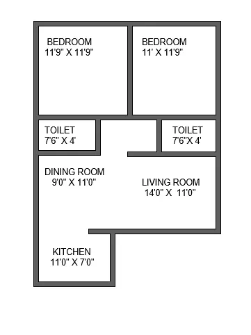
- The plan is created with a witbedroomsroom, 2toilets, a kitchen, a dining room, and a living hall.
- All the room name is provided with dimension.
- Go to the Ribbon > Annotate > Text.
STEP 2
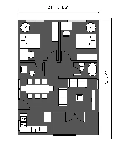
- Go to the Ribbon > Annotate > Linear/Aligned to give the dimension of the layout.
STEP 3
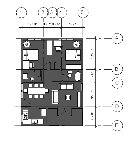
- Open an ARCHITECTURE FLOOR PLAN
- Go to the architecture tab and click on GRID
- Select the line from the modify that and create the one horizontal grid name as A and one vertical line name as 1
- Now again select a grid and select the pick line option from the modify tab and specify distance as and select horizontal line and create a grid from A to E
- again select a grid and select the pick line option from the modify tab and specify the distance and select a vertical line and create a grid from 1 to 5.
- Go to the Ribbon > Annotate > Linear/Aligned to give the dimension of the layout.
STEP 4
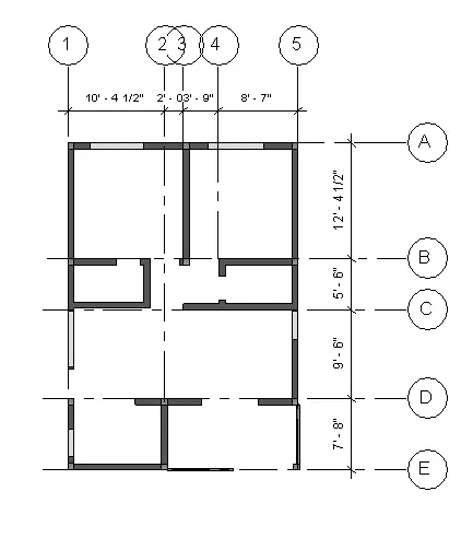
- Open a STRUCTURAL FLOOR PLAN.
- Go to the architecture tab and click on GRID
- Select the line from the modify that and create the one horizontal grid name as A and one vertical line name as 1
- Now again select a grid and select the pick line option from the modify tab and specify distance as and select horizontal line and create a grid from A to E
- again select a grid and select the pick line option from the modify tab and specify the distance and select a vertical line and create a grid from 1 to 5.
- Go to the Ribbon > Annotate > Linear/Aligned to give the dimension of the layout.
TASK 5) Create a sheet template from the view tab and adjust the parameters on the sheet to add appropriate views
AIM -
- TO STUDY THE CREATION OF 3D CEILING, ROOF, ARCHITECTURAL PLAN, STRUCTURAL PLAN, SECTIONAL VIEW, ELEVATION VIEW, AND CAMERA-SPECIFIC VIEW FOR A HOUSE PLAN USING REVIT
INTRODUCTION -
Autodesk Revit is a building information modeling software tool for architects, landscape architects, structural engineers, mechanical, electrical, and plumbing (MEP) engineers, designers, and contractors. The original software was developed by Charles River Software, founded in 1997, renamed Revit Technology Corporation in 2000, and acquired by Autodesk in 2002. The software allows users to design a building and structure and its components in 3D, annotate the model with 2D drafting elements, and access building information from the building model's database. Revit is 4D building information modeling capable with tools to plan and track various stages in the building's lifecycle, from concept to construction and later maintenance and/or demolition
Tools and their function -
- Navigation - we can use the mouse wheel, Project Browser, or View Cube to open a view and navigate to different areas of the model.
- The Project Browser - Located on the lower left of your Revit screen, the Project Browser acts as a table of contents for your project. Use it to navigate and open views of the model. You can organize, sort, filter, and customize the Project Browser to support your workflow.
- The Properties - The Properties palette lets you view and modify parameters for selected elements. If no element is selected, it displays the properties of the current view. The palette appears by default to the left of the drawing area above the Project Browser.
- Temporary Dimensions - As you create or select geometry, Revit displays temporary dimensions around the element. You can use temporary dimensions to dynamically control the placement of elements. Learn more about Temporary Dimensions
- Levels – Levels are finite horizontal planes that act as references for level-hosted elements, such as roofs, floors, and ceilings.
- WALL - Use a Wall tool to create a non-bearing wall or real wall in the building model. Like other basic elements in a building model, walls are instances of predefined system family types, which represent standard varieties of wall function, composition, and thickness
PROCEDURE -
STEP 1
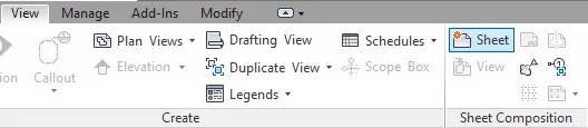
- Go to Ribbon > View > Sheet to create a sheet.
STEP 2
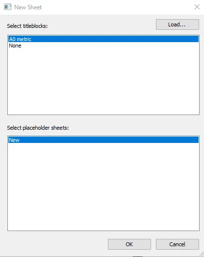
- A new dialog box will open as the name NEW SHEET
- Select an A0 metric and click on OK
STEP 3
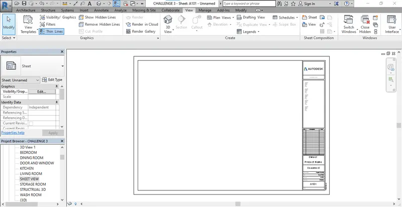
- A sheet will be created on the screen as shown.
STEP 4

STEP 5
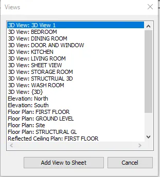
- Go to Ribbon > View > View
- A dialog box will open as the name VIEWS
- Select the file to add to the sheet
- Here, I choose a FLOOR PLAN GROUND LEVEL
- and Click on add view to the sheet.
STEP 6
- The view is added to the sheet as shown in the picture
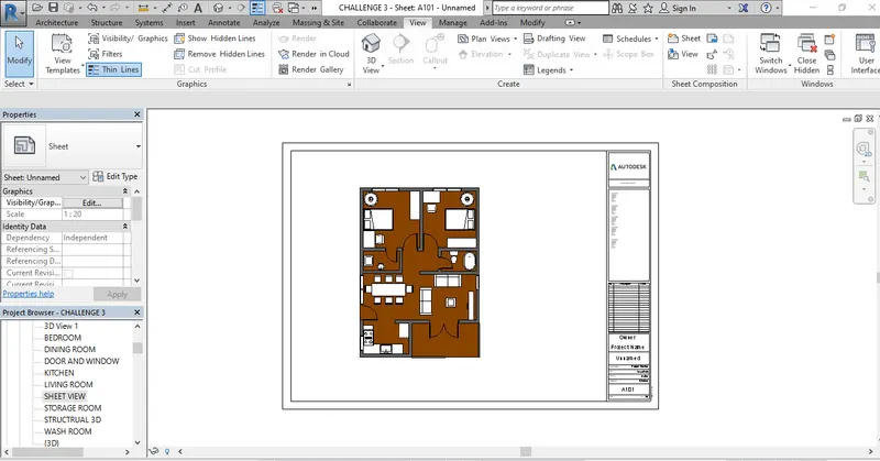
RESULT -
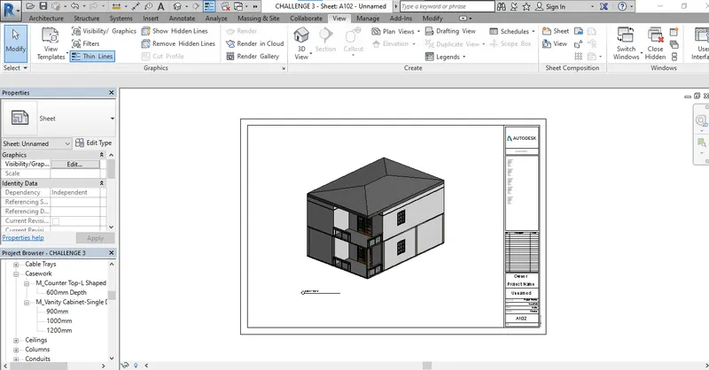
TASK 6) Using the elevation tab create the elevation views, looking at your building from East, North, South, and West
AIM -
- TO STUDY THE CREATION OF 3D CEILING, ROOF, ARCHITECTURAL PLAN, STRUCTURAL PLAN, SECTIONAL VIEW, ELEVATION VIEW, AND CAMERA-SPECIFIC VIEW FOR A HOUSE PLAN USING REVIT
INTRODUCTION -
Autodesk Revit is a building information modeling software tool for architects, landscape architects, structural engineers, mechanical, electrical, and plumbing (MEP) engineers, designers, and contractors. The original software was developed by Charles River Software, founded in 1997, renamed Revit Technology Corporation in 2000, and acquired by Autodesk in 2002. The software allows users to design a building and structure and its components in 3D, annotate the model with 2D drafting elements, and access building information from the building model's database. Revit is 4D building information modeling capable with tools to plan and track various stages in the building's lifecycle, from concept to construction and later maintenance and/or demolition
Tools and their function -
- Navigation - we can use the mouse wheel, Project Browser, or View Cube to open a view and navigate to different areas of the model.
- The Project Browser - Located on the lower left of your Revit screen, the Project Browser acts as a table of contents for your project. Use it to navigate and open views of the model. You can organize, sort, filter, and customize the Project Browser to support your workflow.
- The Properties - The Properties palette lets you view and modify parameters for selected elements. If no element is selected, it displays the properties of the current view. The palette appears by default to the left of the drawing area above the Project Browser.
- Temporary Dimensions - As you create or select geometry, Revit displays temporary dimensions around the element. You can use temporary dimensions to dynamically control the placement of elements. Learn more about Temporary Dimensions
- Levels – Levels are finite horizontal planes that act as references for level-hosted elements, such as roofs, floors, and ceilings.
- WALL - Use a Wall tool to create a non-bearing wall or a true l in the building model. Like other basic elements in a building model, walls are instances of predefined system family types, which represent standard varieties of wall function, composition, and thickness
PROCEDURE -
STEP 1
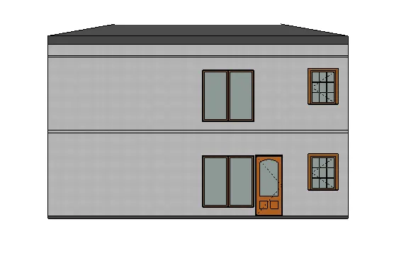
- Go to Ribbon > View > Elevation to create an elevation of the building
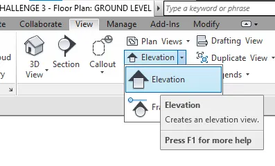
STEP 2
- Place the elevation from all four side directions of the building as shown in the picture
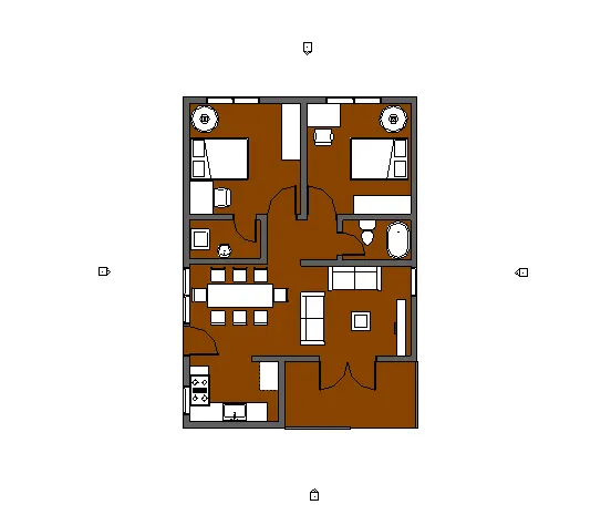
STEP 3
- Go to the project browser and change the name of the elevation an EAST, WEST, NORTH, SOUTH.
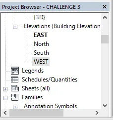
EAST ELEVATION
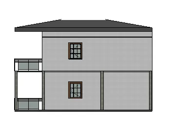
NORTH ELEVATION
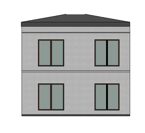
SOUTH ELEVATION
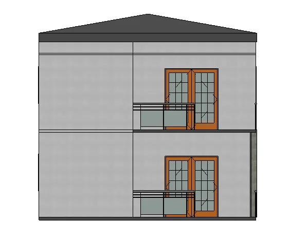
WEST ELEVATION
TASK 7) Produce section cut through each room either cutting across longitudinally or in a transverse direction
AIM -
- TO STUDY THE CREATION OF 3D CEILING, ROOF, ARCHITECTURAL PLAN, STRUCTURAL PLAN, SECTIONAL VIEW, ELEVATION VIEW, AND CAMERA-SPECIFIC VIEW FOR A HOUSE PLAN USING REVIT
INTRODUCTION -
Autodesk Revit is a building information modeling software tool for architects, landscape architects, structural engineers, mechanical, electrical, and plumbing (MEP) engineers, designers, and contractors. The original software was developed by Charles River Software, founded in 1997, renamed Revit Technology Corporation in 2000, and acquired by Autodesk in 2002. The software allows users to design a building and structure and its components in 3D, annotate the model with 2D drafting elements, and access building information from the building model's database. Revit is 4D building information modeling capable with tools to plan and track various stages in the building's lifecycle, from concept to construction and later maintenance and/or demolition
Tools and their function -
- Navigation - we can use the mouse wheel, Project Browser, or View Cube to open a view and navigate to different areas of the model.
- The Project Browser - Located on the lower left of your Revit screen, the Project Browser acts as a table of contents for your project. Use it to navigate and open views of the model. You can organize, sort, filter, and customize the Project Browser to support your workflow.
- The Properties - The Properties palette lets you view and modify parameters for selected elements. If no element is selected, it displays the properties of the current view. The palette appears by default to the left of the drawing area above the Project Browser.
- Temporary Dimensions - As you create or select geometry, Revit displays temporary dimensions around the element. You can use temporary dimensions to dynamically control the placement of elements. Learn more about Temporary Dimensions
- Levels – Levels are finite horizontal planes that act as references for level-hosted elements, such as roofs, floors, and ceilings.
- WALL - Use a Wall tool to create a non-bearing or structural wall in the building model. Like other basic elements in a building model, walls are instances of predefined system family types, which represent standard varieties of wall function, composition, and thickness
PROCEDURE -
STEP 1
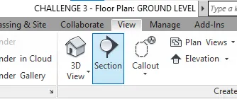
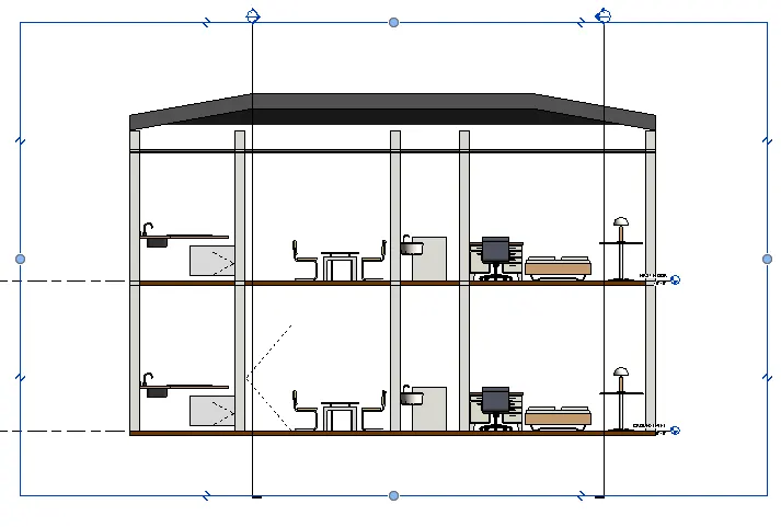
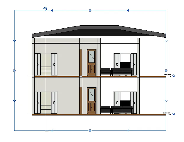
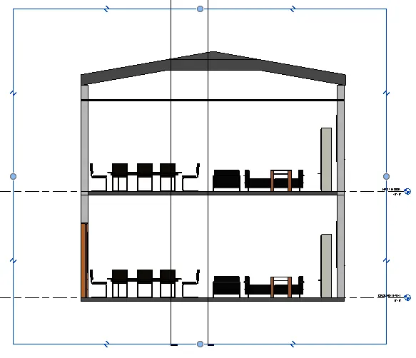
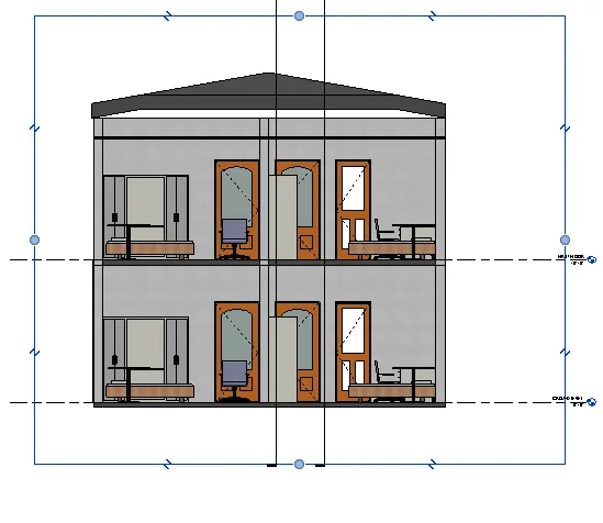
- Go to Ribbon > View > Section to cut the sectional view of the building
STEP 2
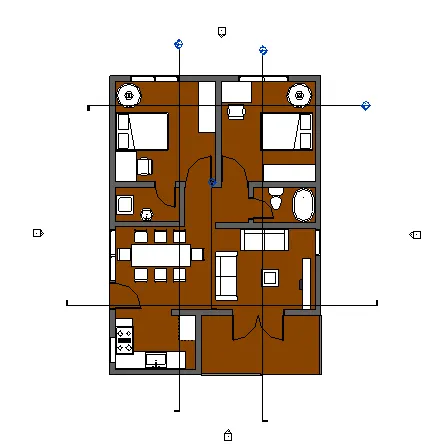
- Specify the first point and second point of the section line as shown in the picture.
- Here, I create a 5 sectional view of the building
STEP 3
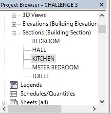
- Go to the project browser and change the name of the Sectional view to the name of the room.
RESULT-
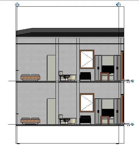
SECTION A - A'
SECTION B - B'
SECTION 1 - 1'
SECTION 2 - 2'
SECTION OF TOILET, LIVING, AND BEDROOM
TASK 8) Classify the views, Plan Views, Section Views, and Elevation views to either Design or Documentation category using the Properties browser
AIM -
- TO STUDY THE CREATION OF 3D CEILING, ROOF, ARCHITECTURAL PLAN, STRUCTURAL PLAN, SECTIONAL VIEW, ELEVATION VIEW, AND CAMERA CAMERA SPECIFIC A HOUSE PLAN USING REVIT
INTRODUCTION -
Autodesk Revit is a building information modeling software tool for architects, landscape architects, structural engineers, mechanical, electrical, and plumbing (MEP) engineers, designers, and contractors. The original software was developed by Charles River Software, founded in 1997, renamed Revit Technology Corporation in 2000, and acquired by Autodesk in 2002. The software allows users to design a building and structure and its components in 3D, annotate the model with 2D drafting elements, and access building information from the building model's database. Revit is 4D building information modeling capable with tools to plan and track various stages in the building's lifecycle, from concept to construction and later maintenance and/or demolition
Tools and their function -
- Navigation - we can use the mouse wheel, Project Browser, or View Cube to open a view and navigate to different areas of the model.
- The Project Browser - Located on the lower left of your Revit screen, the Project Browser acts as a table of contents for your project. Use it to navigate and open views of the model. You can organize, sort, filter, and customize the Project Browser to support your workflow.
- The Properties - The Properties palette lets you view and modify parameters for selected elements. If no element is selected, it displays the properties of the current view. The palette appears by default to the left of the drawing area above the Project Browser.
- Temporary Dimensions - As you create or select geometry, Revit displays temporary dimensions around the element. You can use temporary dimensions to dynamically control the placement of elements. Learn more about Temporary Dimensions
- Levels – Levels are finite horizontal planes that act as references for level-hosted elements, such as roofs, floors, and ceilings.
- WALL - Use a Wall tool to create a non-bearing wall or real wall in the building model. Like other basic elements in a building model, walls are instances of predefined system family types, which represent standard varieties of wall function, composition, and thickness
PROCEDURE -
STEP 1
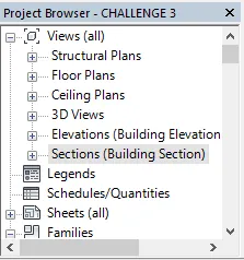
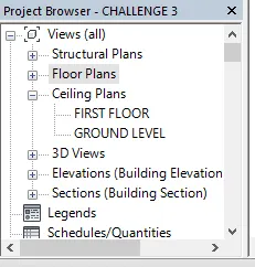
- Go to the ProjectBrower and open the view by clicking the + icon which is present infornt of the view
- In the view we create 6 types of views that are Structural plans, Floor Plans, Ceiling plans 3D views, Elevation, and sections.
STEP 2
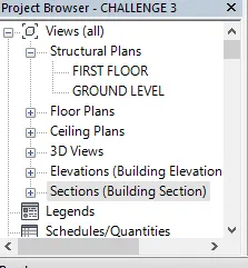
- Go to the Project Brower and open the structural plan by clicking the + icon which is present in front of the structural plan
- Two views are created in the structural plan as shown in the picture.
STEP 3
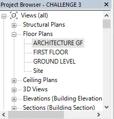
- Go to the Project Brower open the Floor plan by clicking the + icon which is present in front of the Floor plan
- Four views are created in the Floor plan as shown in the picture.
STEP 4
- Go to the Project Brower open the Ceiling plan by clicking the + icon which is present in front of the Ceiling plan
- Two views are created in the Ceiling plan as shown in the picture.
STEP 5
- Go to the Project Brower open the 3D Views by clicking the + icon which is present in front of the 3D Views
- These views are created in the 3d Views as shown in the picture.

STEP 6
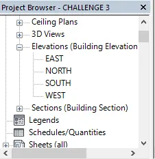
- Go to the Project Brower open the Elevation by clicking the + icon which is present in front of the Elevation
- These views are created in the Elevation as shown in the picture.
STEP 7
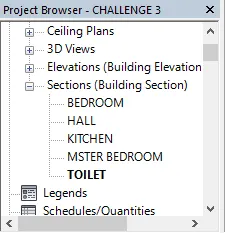
- Go to the Project Brower open the Sections by clicking the + icon which is present in front of the Sections
- These views are created in the Sections as shown in the picture.
TASK 9) Using the sheet template produced create multiple sheets as follows
a. A 101- Ground Floor Architecture Plan
b. A 102- First Floor Architecture Plan
c. A 103- Roof Plan
d. S 101- Ground Floor Structural Plan
e. S 102- First Floor Structural Plan
f. S 103- Roof Framing Plan
g. A-201- North-South Elevations
h. A-202- East-West Elevations
Add additional sheets based on the sections created in your Revit file
AIM -
- TO STUDY THE CREATION OF 3D CEILING ROOF, ARCHITECTURAL PLAN, STRUCTURAL PLAN, SECTIONAL VIEW, ELEVATION VIEW, AND CAMERA-SPECIFIC VIEW FOR A HOUSE PLAN USING REVIT
INTRODUCTION -
Autodesk Revit is a building information modeling software tool for architects, landscape architects, structural engineers, mechanical, electrical, and plumbing (MEP) engineers, designers, and contractors. The original software was developed by Charles River Software, founded in 1997, renamed Revit Technology Corporation in 2000, and acquired by Autodesk in 2002. The software allows users to design a building and structure and its components in 3D, annotate the model with 2D drafting elements, and access building information from the building model's database. Revit is 4D building information modeling capable with tools to plan and track various stages in the building's lifecycle, from concept to construction and later maintenance and/or demolition
Tools and their function -
- Navigation - we can use the mouse wheel, Project Browser, or View Cube to open a view and navigate to different areas of the model.
- The Project Browser - Located on the lower left of your Revit screen, the Project Browser acts as a table of contents for your project. Use it to navigate and open views of the model. You can organize, sort, filter, and customize the Project Browser to support your workflow.
- The Properties - The Properties palette lets you view and modify parameters for selected elements. If no element is selected, it displays the properties of the current view. The palette appears by default to the left of the drawing area above the Project Browser.
- Temporary Dimensions - As you create or select geometry, Revit displays temporary dimensions around the element. You can use temporary dimensions to dynamically control the placement of elements. Learn more about Temporary Dimensions
- Levels – Levels are finite horizontal planes that act as references for level-hosted elements, such as roofs, floors, and ceilings.
- WALL - Use a Wall tool to create a non-bearing wall or a true l in the building model. Like other basic elements in a building model, walls are instances of predefined system family types, which represent standard varieties of wall function, composition, and thickness
PROCEDURE -
STEP 1
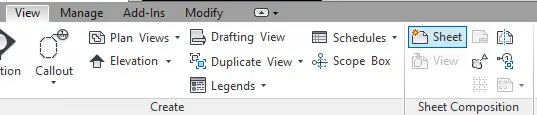
- Go to Ribbon > View > Sheet to create a sheet.
STEP 2
- A new dialog box will open as the name NEW SHEET
- Select an A0 metric and click on OK
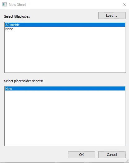
STEP 3
- A sheet will be created on the screen as shown.
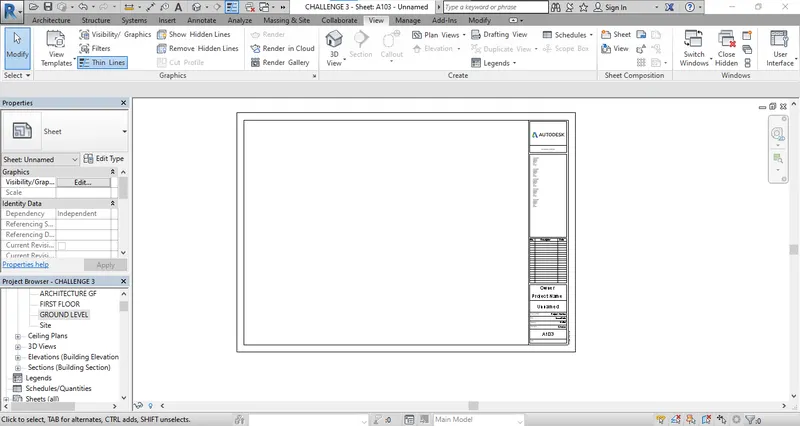
STEP 4
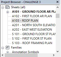
- Go to the Project Browser a shhet is create as name A101-Unamed
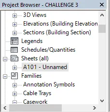
STEP 5
- Go to the Project Browser and rename the sheet as A101 -GROUND FLOOR ARCHITECTURAL PLAN
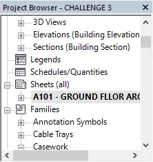
STEP 6
- Create a 8 sheet with name given in the task as shown in the picture.
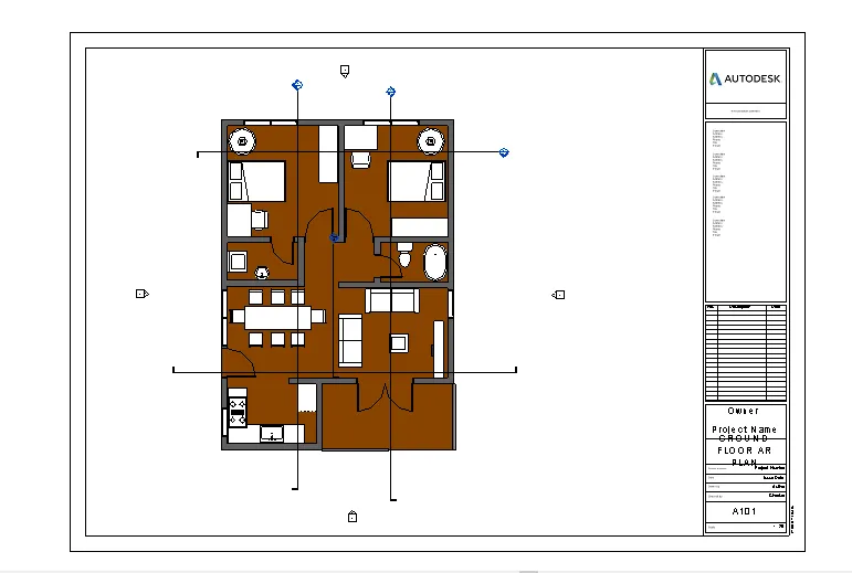
RESULT -
A 101- Ground Floor Architecture Plan
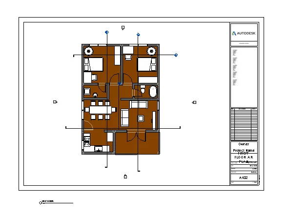
A 102- First Floor Architecture Plan
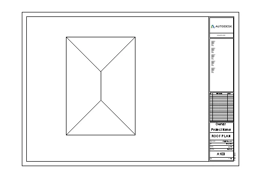
A 103- Roof Plan
S 101- Ground Floor Structural Plan
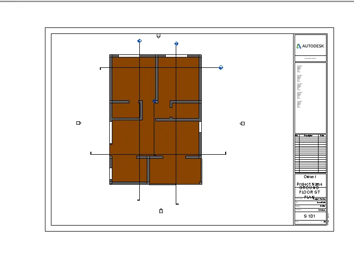
S 102- First Floor Structural Plan
S 103- Roof Framing Plan
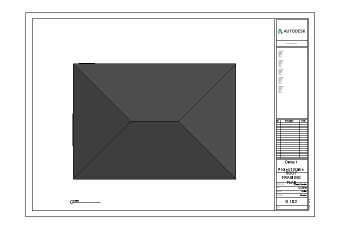
A-201- North-South Elevations
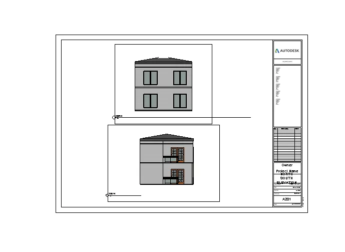
A-202- East-West Elevations
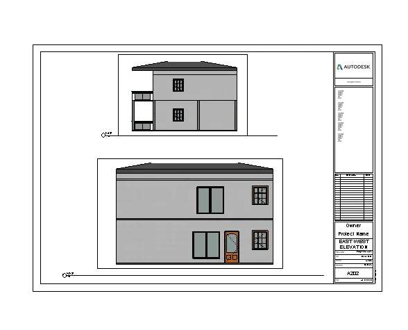
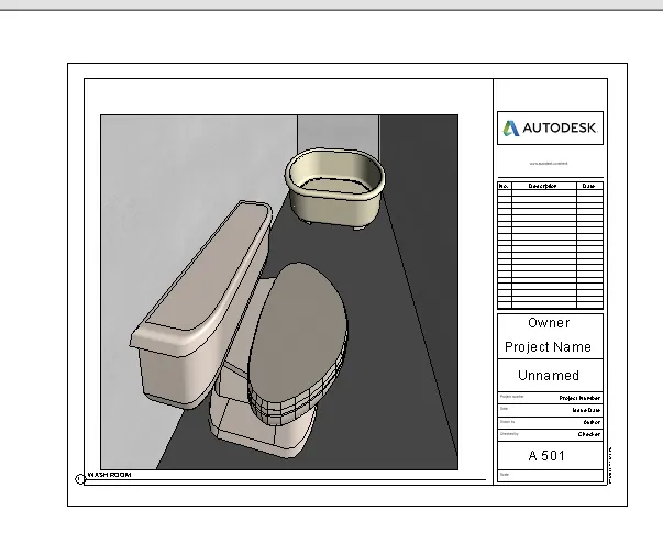
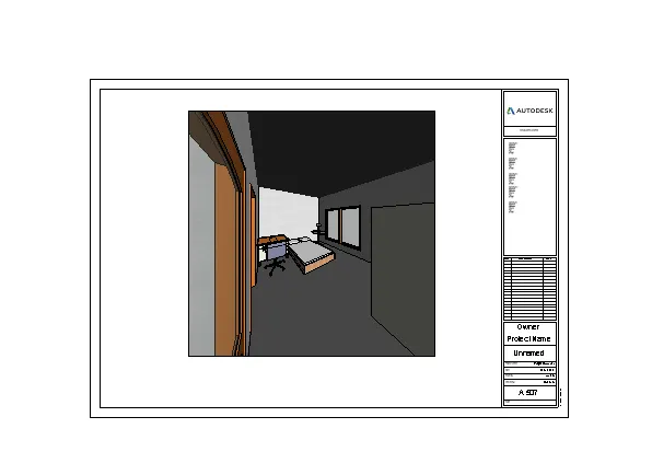
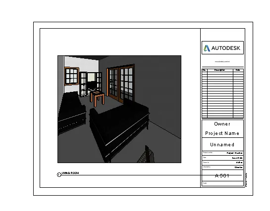
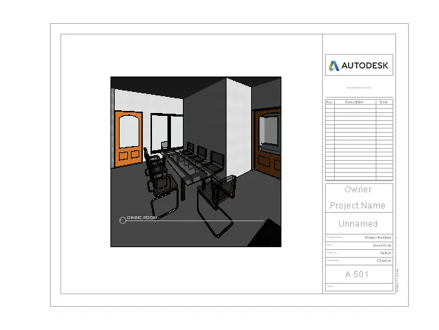
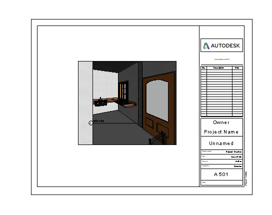
TASK 10) Create a camera-specific view in each room ( living, dining, bedroom). Based on the views create a new set of sheets starting A-501 (you can add as many sheets after, 502, 503.. n)to place the 3D view images. Produce the sheets as a part of project drafting.
AIM -
- TO STUDY THE CREATION OF 3D CEILING, ROOF, ARCHITECTURAL PLAN, STRUCTURAL PLAN, SECTIONAL VIEW, ELEVATION VIEW, AND CAMERA-SPECIFIC VIEW FOR A HOUSE PLAN USING REVIT
INTRODUCTION -
Autodesk Revit is a building information modeling software tool for architects, landscape architects, structural engineers, mechanical, electrical, and plumbing (MEP) engineers, designers, and contractors. The original software was developed by Charles River Software, founded in 1997, renamed Revit Technology Corporation in 2000, and acquired by Autodesk in 2002. The software allows users to design a building and structure and its components in 3D, annotate the model with 2D drafting elements, and access building information from the building model's database. Revit is 4D building information modeling capable with tools to plan and track various stages in the building's lifecycle, from concept to construction and later maintenance and/or demolition
Tools and their function -
- Navigation - we can use the mouse wheel, Project Browser, or View Cube to open a view and navigate to different areas of the model.
- The Project Browser - Located on the lower left of your Revit screen, the Project Browser acts as a table of contents for your project. Use it to navigate and open views of the model. You can organize, sort, filter, and customize the Project Browser to support your workflow.
- The Properties - The Properties palette lets you view and modify parameters for selected elements. If no element is selected, it displays the properties of the current view. The palette appears by default to the left of the drawing area above the Project Browser.
- Temporary Dimensions - As you create or select geometry, Revit displays temporary dimensions around the element. You can use temporary dimensions to dynamically control the placement of elements. Learn more about Temporary Dimensions
- Levels – Levels are finite horizontal planes that act as references for level-hosted elements, such as roofs, floors, and ceilings.
- WALL - Use a Wall tool to create a non-bearing or structural wall in the building model. Like other basic elements in a building model, walls are instances of predefined system family types, which represent standard varieties of wall function, composition, and thickness
PROCEDURE -
STEP 1
- Go to Ribbon > View > Sheet to create a sheet.
STEP 2
- A new dialog box will open as the name NEW SHEET
- Select an A0 metric and click on OK
STEP 3
- A sheet will be created on the screen as shown.
STEP 4
- Create a seven sheet with sheet number 501, 502, 503 and so on.
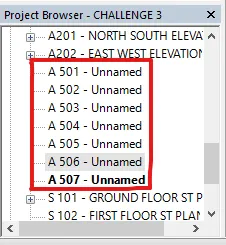
RESULT -
BEDROOM
LIVING ROOM
DINING ROOM
KITCHEN
WASH AREA
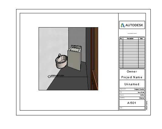
TOILET-