3D Creation of Celing, Roof, Architectural plan, Structural plan, Sectional view, Elevation view and Camera specific view for a house plan using REVIT
1) Based on the project saved from Week 3, proceed from the First Floor Level. Model a Ceiling from the architecture tab above the walls at the first-floor level
Aim:
Model of Ceiling from the architecture tab above the walls at the first-floor level
procedure:
I. Open the project file
II. Open Revit from the window and then in the Revit tab
III. click on the file option
IV. then click on open
V. next browse for the file project 1 ( which was saved previously) to open and click on it
VI. go to menu bar
VII. here select the architecture bar
VIII. and select the ceiling option
IX. then in the properties bar select the ceiling
X. and click on the edit type for changing the any properties of the ceiling
XI. now in the menu bar select the sketch ceiling option
XII. in the floor plan by pick line command select the boundary of the ceiling required as shown in the figure below
XIII.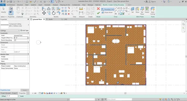
XIV. In the properties bar specify the height offset from level as the 9’ 0”
XV. i.e., the ceiling height
XVI. click on the green right mark as done
XVII. ceiling as shown in the figure below will be created
XVIII.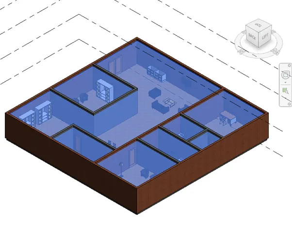
Result:
Ceiling model was created
2) Model a roof above the ceiling by selecting the footprints of the ceiling. Using the adjustment toolbars appearing on-screen adjust the roof slope to 10 degrees
Aim:
Model of a roof above the ceiling by selecting the footprints of the ceiling. Using the adjustment toolbars appearing on-screen adjust the roof slope to 10 degrees
Procedure:
I. in the project browser
II. select the 3d view
III. In the menu bar
IV. Go to the architecture tab
V. And click on the roof option
VI. Then there would be the drop down of different options as shown in the figure below
VII.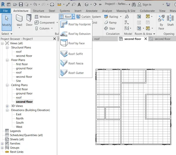
VIII. Here, select the roof by footprint option
IX. In the pop up select the working plane as the second floor
X. In the menu bar select the pick lines option
XI. And in 3d view pick the boundary lines of the roof
XII. Esc
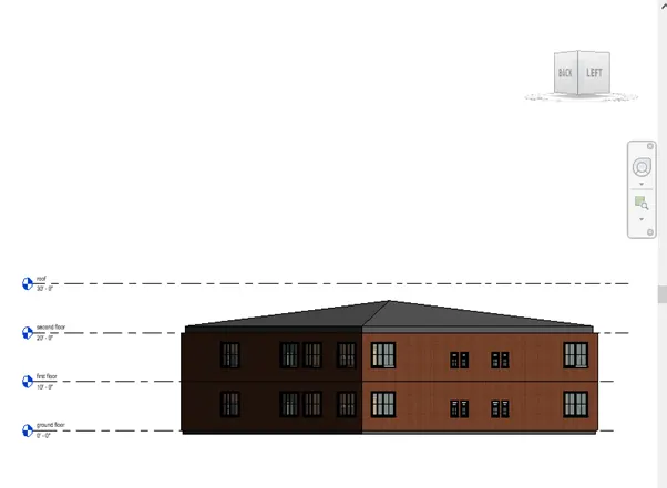
XIII. And select the line individually and chage the roof slope to 10 degrees as shiown in the figure below
XIV.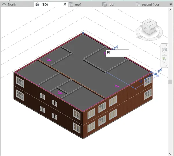
XV. In the menu bar click on the green right symbol
XVI. Esc
Result:
Roof of footprint with 10 degree roof slope was modelled
3) Using the file saved from weeks 2 to 4, create plan views for ground floor level and first-floor level including all the walls, floors, and components. Separate them to architecture and structural plans
Aim:
Certation of the architectural and the structural plans of the ground floor and first floor
Procedure:
a. Architecture plan must have walls, floors, and all the components placed within the building
I. Go to the menu bar
II. Select the view command bar
III. Select the plan view options drop down falls
IV. Here select the architectural floor plan as shown in the figure below
V.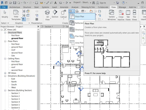
VI. Then select the floors that required to be shown as the floor plan
VII. By pressing the ctrl key in the keyboard select all the floors of the which plans have to be obtained as shown in the figure below
VIII.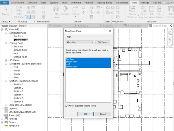
IX. Click ok
X. Go to the project browser
XI. In the floor plans select the plan which has to be viewed
XII. Ie, ground floor
XIII.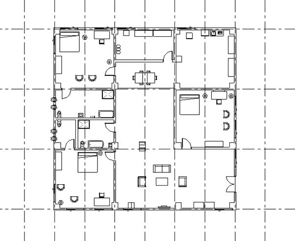
XIV. First floor
XV.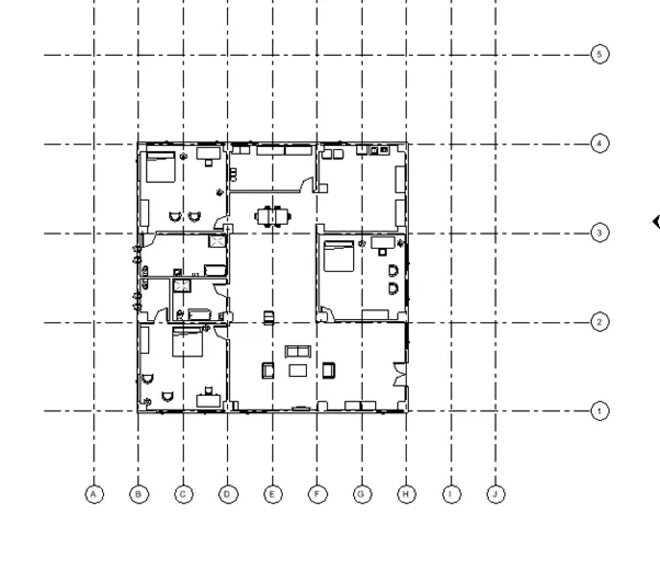
b. Structure plan must have details of only walls, floors, and columns
I. Go to the menu bar
II. Select the view command bar
III. Select the plan view options drop down falls
IV. Here select the structural floor plan as shown in the figure below
V.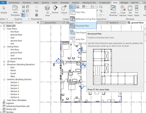
VI. Then select the floors that required to be shown as the structural floor
VII. By pressing the ctrl key in the keyboard select all the floors of the wich plans have to be obtained as shown in the figure below
VIII.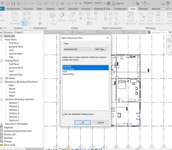
IX. Click ok
X. Go to the project browser
XI. In the structural plans select the plan which has to be viewed
XII. Ie, ground floor
XIII. Right click on the ground floor and click on the properties option
XIV. Next go to the properties tab
XV. In visibility/graphics option click on the edit
XVI. Then in the pop up click on all the required visible options i.e., columns, doors, windows and other structural elements
XVII.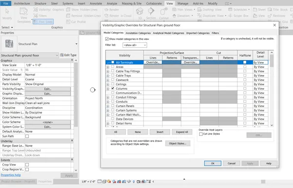
XVIII. Next select the first floor and repeat the same procedure and click apply and press ok
XIX. Ground floor
XX.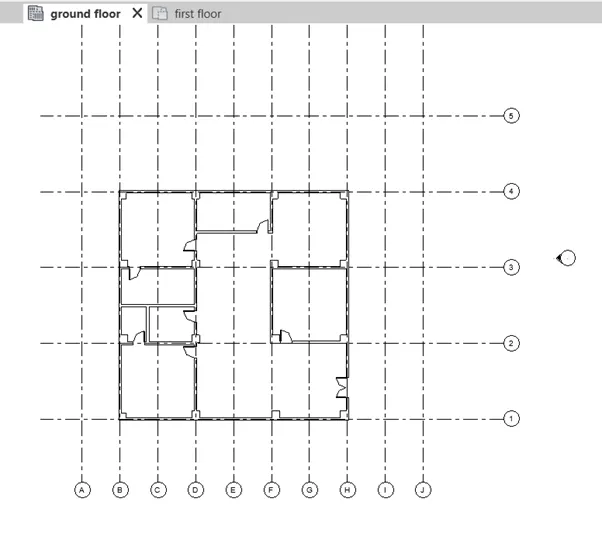
XXI. First floor
XXII.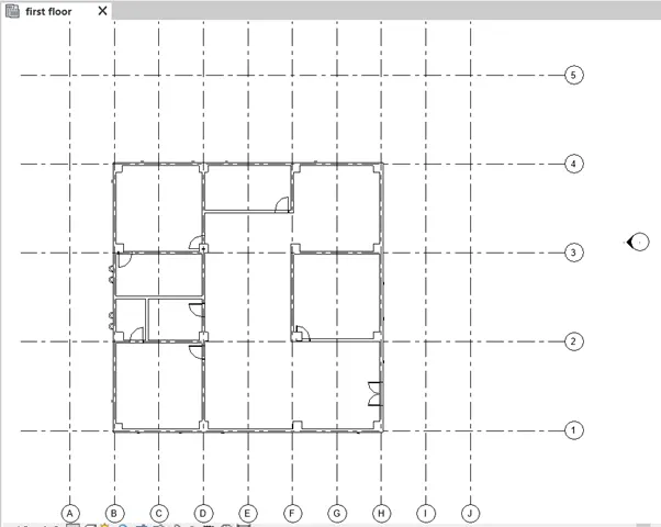
Result:
Structural and architectural plans were created
4) Using annotate toolbar add dimensions to all the walls and floors with reference to the longitudinal and transverse grids created in the project file
Aim:
Using annotate toolbar add dimensions to all the walls and floors with reference to the longitudinal and transverse grids created in the project file
a. The architecture plan dimensions include details on where the components are placed within the buildings with relation to grids. Overall dimensions are sufficient for architecture plans
I. In the menu bar go to the annotate bar and select the aligned dimensions option
II. Now select the walls in which distance between has to be measured
III. First click on the first wall
IV. And then click on the next wall
V. Similarly measure the all the required dimensions
VI. Also using snapping also measure the distance between all the instances as the reference
VII. Final output will be as shown in the figure below
VIII.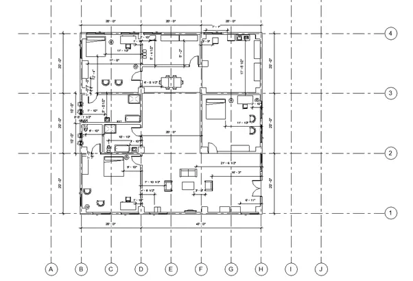
b. The Structure plan dimensions must include details on the position of all the walls and interior walls with reference to grids. Locate all the framing components of the building with reference to a fixed point using Structural plans
I. In the menu bar go to the annotate bar and select the aligned dimensions option
II. Now select the walls in which distance between has to be measured
III. First click on the first wall
IV. And then click on the next wall
V. Similarly measure the all the required dimensions
VI. Final output will be as shown in the figure below
VII.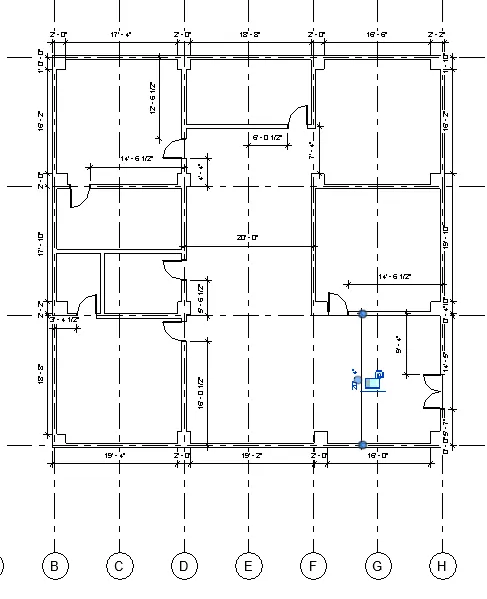
Result:
Structural and architectural drawings with the annotations were provided
5) Create a sheet template from the view tab and adjust the parameters on the sheet to add appropriate views
Aim:
Creation of a sheet template from the view tab and adjust the parameters on the sheet to add appropriate views
Procedure:
I. In the menu bar
II. Select the view command bar
III. And select the sheet option
IV. Then there will be a pop up
V. Here click on the load option
VI. And the go to title block categories
VII. And select the required template and click ok
VIII.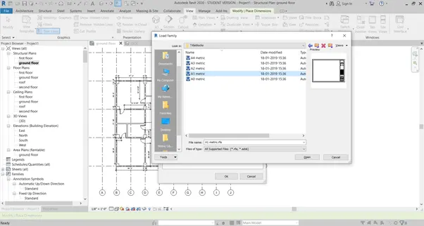
IX. Next click on the attributes in the title block
X. Go to manage command in the menu bar
XI. Then click on the project information icon
XII. And in popup fill all the information of the project
XIII. Change the required changes
XIV.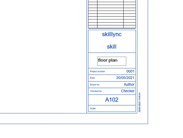
XV. Adding the views to the sheet
XVI. Go to the view command in the title block
XVII. Click on the view option
XVIII. And in the pop up select the required view to be displayed in the sheet
XIX. And click ok
XX. Sheet shown in the following image will be obtained
XXI.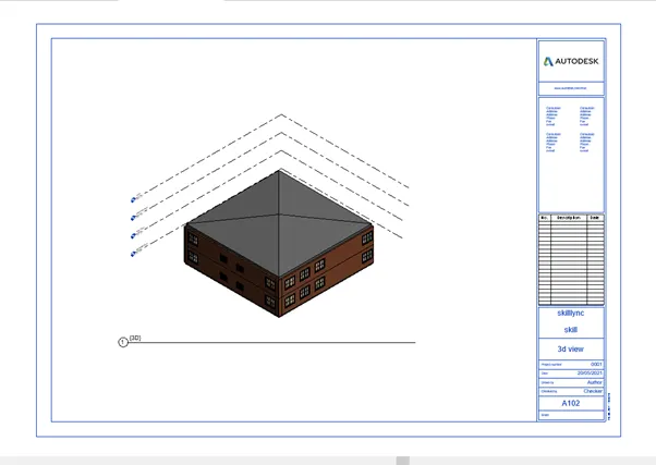
XXII. Esc
Result:
Sheet template from the view tab was created
6) Using the elevation tab create the elevation views, looking at your building from East, North, South, and West
Aim:
Using the elevation tab creating the elevation views, looking at your building from East, North, South, and West
Procedure
I. Go to the menu bar
II. Select the view bar
III. In view bar select the elevation option as shown in the figure below
IV.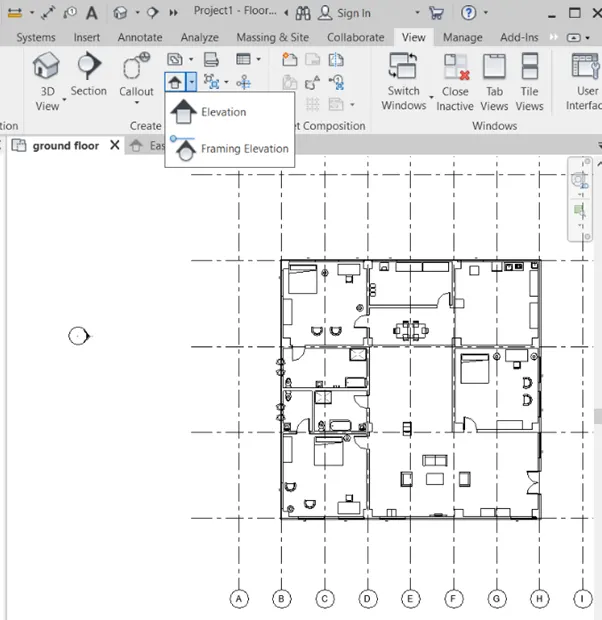
V. Come to the floor plan and move cursor downward and snap for the north elevation
VI. Then in the property browser select the north in elevation
VII. Following ele vation will be displayed
VIII.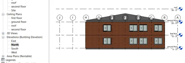
IX. Come to the floor plan and move cursor upward and snap for the south elevation
X. Then in the property browser select the south in elevation
XI. Following elevation will be displayed
XII.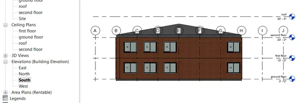
XIII. Come to the floor plan and move cursor rightwards and snap for the west elevation
XIV. then in the property browser select the west in elevation
XV. Following elevation will be displayed
XVI.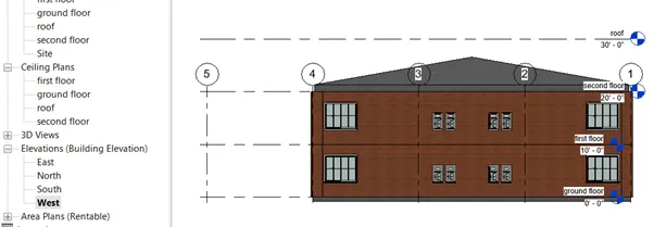
XVII. Come to the floor plan and move cursor leftwards and snap for the east elevation
XVIII. Then in the property browser select the east in elevation
XIX. Following elevation will be displayed
XX.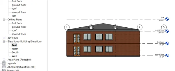
Result:
All elevations in the north, south, east and west direction of the building/model was created.
7) Produce section cut through each room either cutting across longitudinally or in a transverse direction
Aim:
Creating the section cut through each room either cutting across longitudinally or in a transverse direction
Procedure:
I. Go to the menu bar
II. Select the view bar
III. In view bar select the section option as shown in the figure below
IV.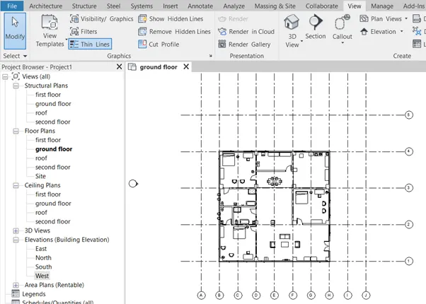
V. Draw the line /section into the bedroom
VI. Then from the property browser select this section
VII. It will be displayed as below
VIII.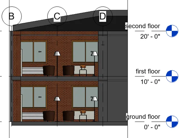
IX. Draw the line /section into the bathroom
X. Then from the property browser select this section
XI. It will be displayed as below
XII.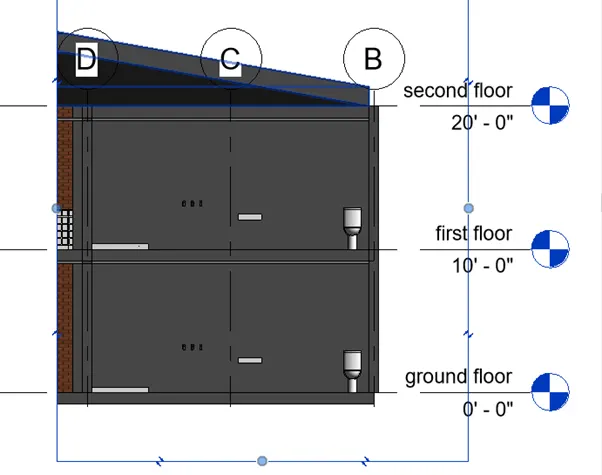
XIII. Draw the line /section into the dining room
XIV. Then from the property browser select this section
XV. It will be displayed as below
XVI.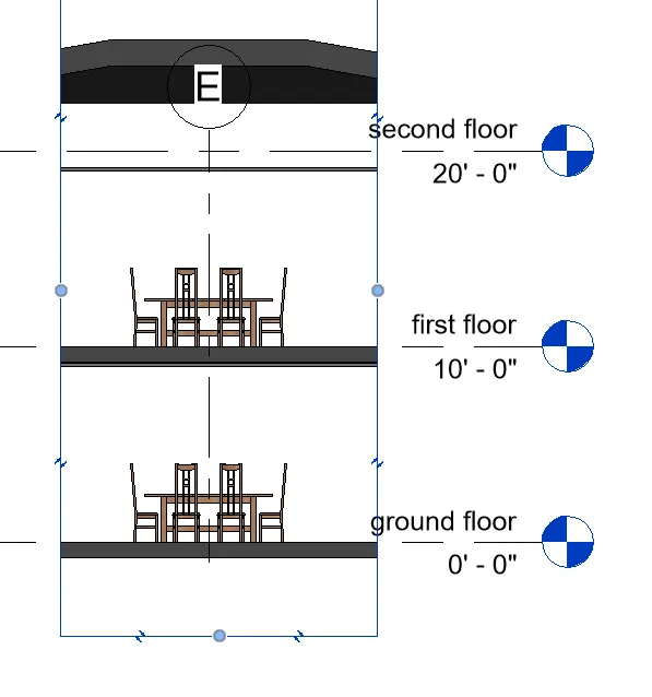
XVII. Draw the line /section into the living room
XVIII. Then from the property browser select this section
XIX. It will be displayed as below
XX.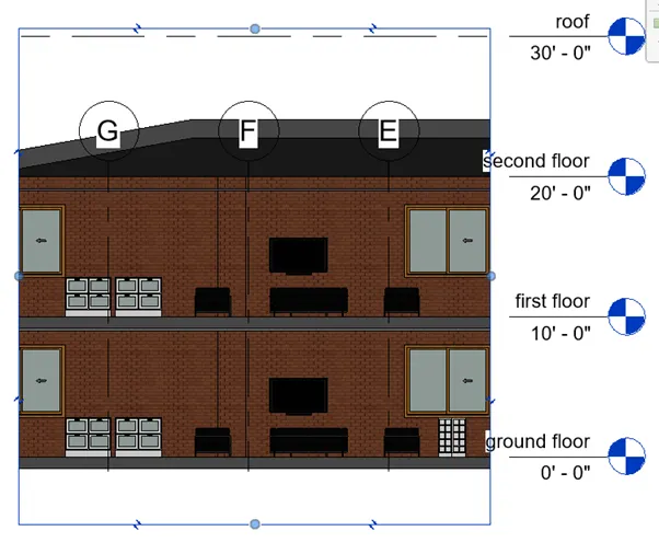
XXI. Draw the line /section into the kitchen
XXII. Then from the property browser select this section
XXIII. It will be displayed as below
XXIV.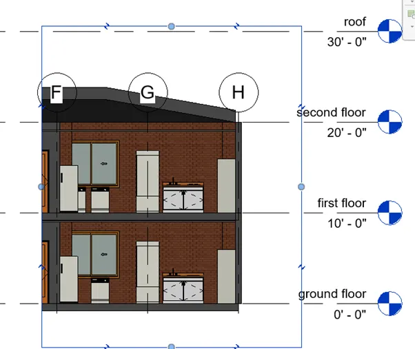
XXV. Draw the line /section into the storage room
XXVI. Then from the property browser select this section
XXVII. It will be displayed as below
XXVIII.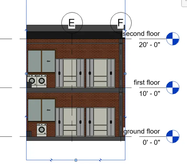
Result:
All the required sections were created on the model
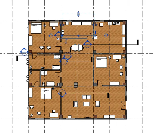
8) Classify the views, Plan Views, Section Views, and Elevation views to either Design or Documentation category using Properties browser
Views in the Revit are classified into the
I. Structural plans
II. Floor plans
III. Ceiling plans
IV. 3d views
V. Elevations
VI. Sections
VII. Area plans
Plan views:
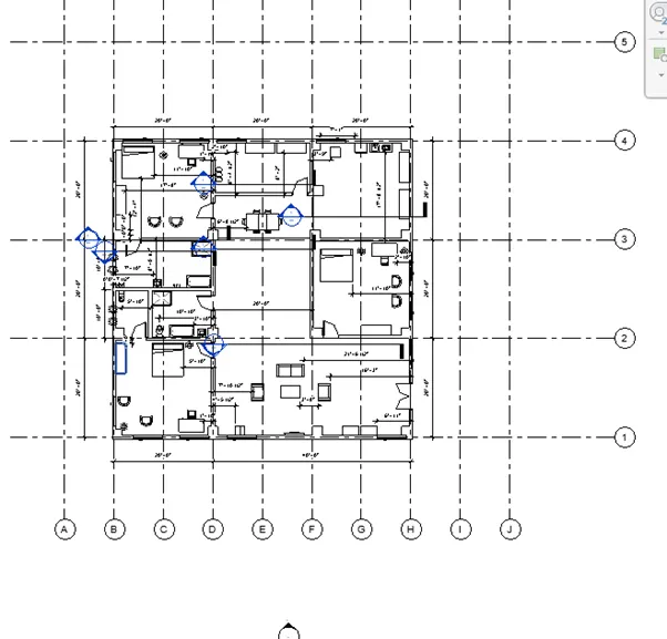
Where structural plans provide us the structural features of the project. These plans can be provided to the all the levels of the building and at least one plan would be provided for the one project. It shows the details of the columns, and other structural elements present on the plan
Floor plans are provided to showcase the all the instance present in the particular level with the help of the annotations we can also provide the dimension of the all instances where it has to be placed and positions of the models.
Section views:
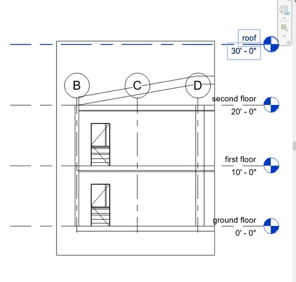
These are the views we require for the better understanding of the model as these elevations provide us the elevation view of the model at any position of the model. These sections can provide us at any height as per our requirements
Elevation views:
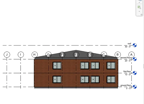
These are the views which are provided at the required directions i.e., north, south, east and west which provides the transverse views of the model of the project
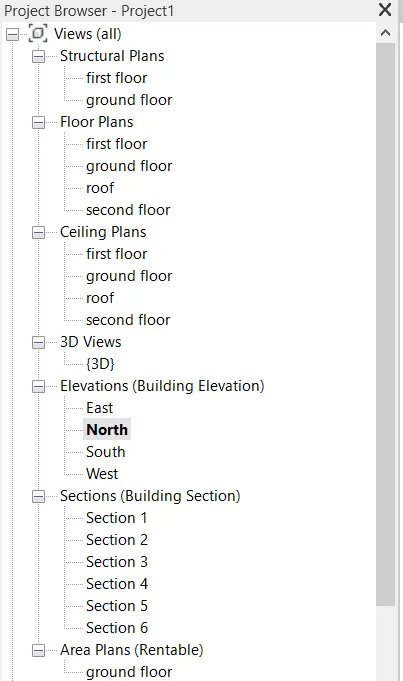
All these views can be managed in the project browser by the clicking on them
9) Using the sheet template produced create multiple sheets as follows
Aim:
Create the sheet templates with the following views
procedure:
I. Adding the views to the sheet
II. Go to the view command in the title block
III. Click on the view option
IV. And in the pop up select the required view to be displayed in the sheet
V. And click ok
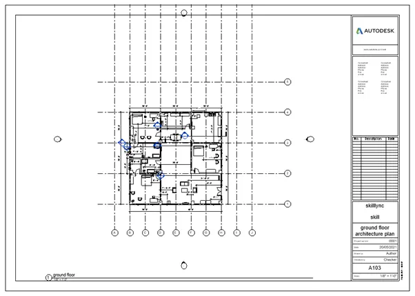
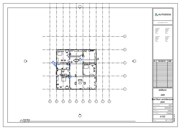
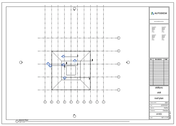
VI. Sheet shown in the following images will be obtained
a. A 101- Ground Floor Architecture Plan
b. A 102- First Floor Architecture Plan
c. A 103- Roof Plan
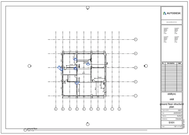
d. S 101- Ground Floor Structural Plan
in the project browser rename the sheet to s101
e. S 102- First Floor Structural Plan
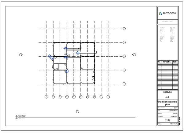
f. S 103- Roof Framing Plan
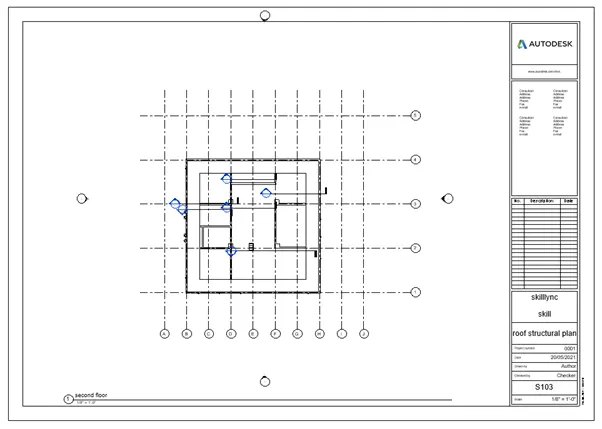
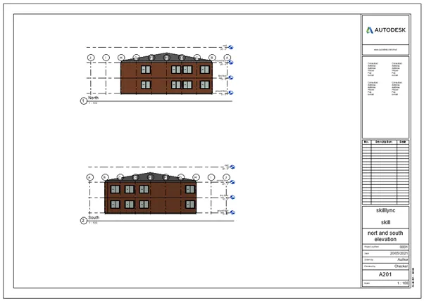
g. A-201- North-South Elevations
in the project browser rename the sheet to the A201
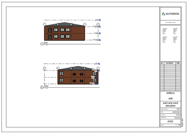
h. A-202- East-West Elevations
Add additional sheets based on the sections created in your Revit file
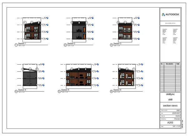
Result:
All the required sheet templets with the respective views were created
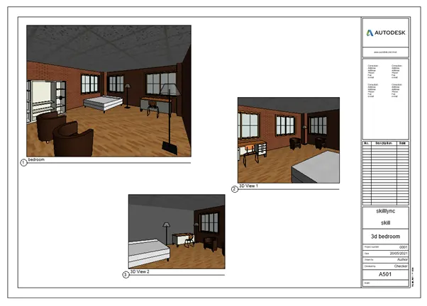
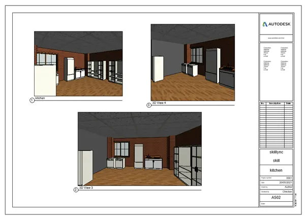
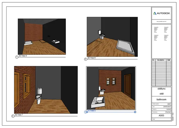
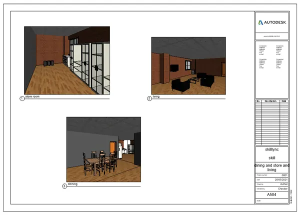
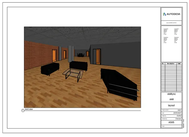
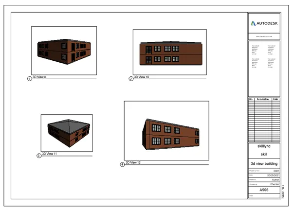
10) Create a camera-specific view or a 3D view in each room ( living, dining, bedroom). Based on the views create a new set of sheets starting A-501 (you can add as many sheets after, 502, 503.. n)to place the 3D view images. Produce the sheets as a part of project drafting.
Aim:
Creating a camera-specific view or a 3D view in each room ( living, dining, bedroom). Based on the views create a new set of sheets starting A-501 (you can add as many sheets after, 502, 503.. n)to place the 3D view images.
Procedure:
I. Go to the menu bar
II. And select the view command bar
III. Here drag down on the 3d view
IV. And select the camera option
V. Click on the any required position and dray the projection of the camera and place it
VI. Go to the project browser and select the respective view and rename it.
VII. Go to the view command in the title block
VIII. Click on the view option
IX. And in the pop up select the required view to be displayed in the sheet
X. And click ok
XI. Sheet shown in the following images will be obtained
XII. Repeat the procedure for all the steps and obtain the below sheets
Bedroom
Kitchen
Bathroom
Store room, living and dinning
Layout
3d view
Result:
Required 3d views were obtained and sheet templates were provided