3D Creation of Ceiling, Roof, Architectural plan, Structural plan, Sectional view, Elevation view and Camera specific view for a house plan using REVIT
Q1)
AIM:
To model a ceiling from the architecture tab above the walls at the first - floor level.
INTRODUCTION:
* The creation of ceiling within revit is a very similar process to that of floors and roofs- ie you can let revit do most of the work and "gress" where you want the boundaries to be. or you can enter sketch mode and literally sketch out the boundary of the ceiling yourself.
* The main thing to remember is to be in the connect ceiling plan view before you start. revit will let you place ceilings in floor plan.
* Views, but i would not advise this as you cannot readily see what you have created.
PROCEDURE:
Step 1:
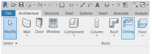
* First we open the revit software, and select the ceiling option from the architecture toolbar.
Step 2:
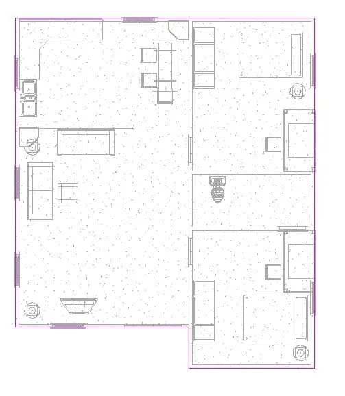
* Sketch the boundries by pick planes as shown below.
Step 3:
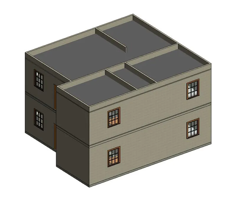
The ceiling of the residential building created and shown in 3D view.
RESULT:
The ceiling has been modeled successfully from the architectural tab above the walls at the first floor level.
Q2)
AIM:
To model a roof above the ceiling by selecting the footprints of the ceiling.
INTRODUCTION:
* Roof, covering of the top of a building, serving to protect against rain snow, sunlight wind, and extreme of temperature
* Roofs have been constructed in a wide variety of forms flat, pitched, vaulted, domed, or in combination as dictated by technical. economic, or aesthetic consideration the earliest roofs constructed by man were probably thatched roofs that were made of straw.
* Leaves, branches, or reeds; they were usually set at a slope, or pitch, so that rainfall could drain off them.
* Conical thatched roofs are a good example of this type and are still widely used in the rural areas of africa and elsewhere
* Thicker branches and timbers eventually came to be used to span a roof, with clay or some other relatively impermeable substance pressed into the interstices between them.
* Gabled and flat roofs were possible with these materials. with the invention of brick and cut stone for building, the basic roof form of the dome and vault appeared.
PROCEDURE:
Step 1:
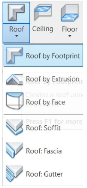
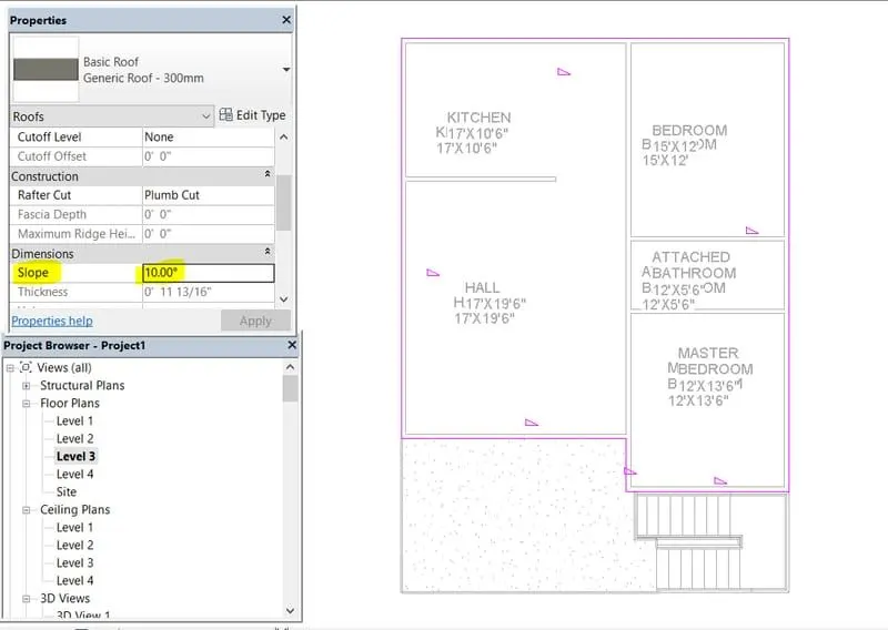
* Open the architecture toolbar, and select the roof by footprint option as shown in the below figure.
Step 2:
* Now select the footprint roof and change the slope to 10 degree.
Step 3:
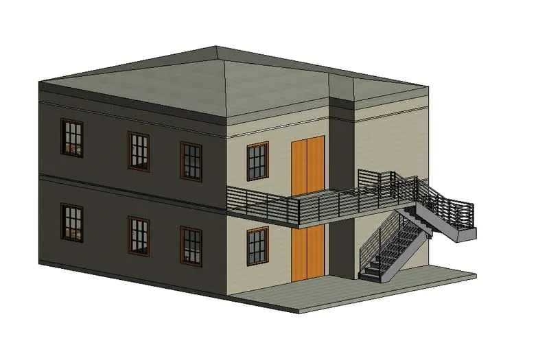
The roof has been created.
RESULT:
The roof has been created and the slope is adjusted to 10 degree.
Q3)
AIM:
To create plan views for ground floor level and first- floor level including all the walls, floors, and components and to separate them to architecture and structural plans
INTRODUCTION:
* The structural plan view is the default view when you start a new project using a structural template. most projects include at least one structural plan. New structural plan views are created automatically as you add new levels to your projects. you can create multiple structural plan view types
* The floor plan view is the default view in a new architectural projects- most projects include at least one floor plan.
* Floor plan views are created automatically as you add new levels to your projects.
PROCEDURE:
Step 1:
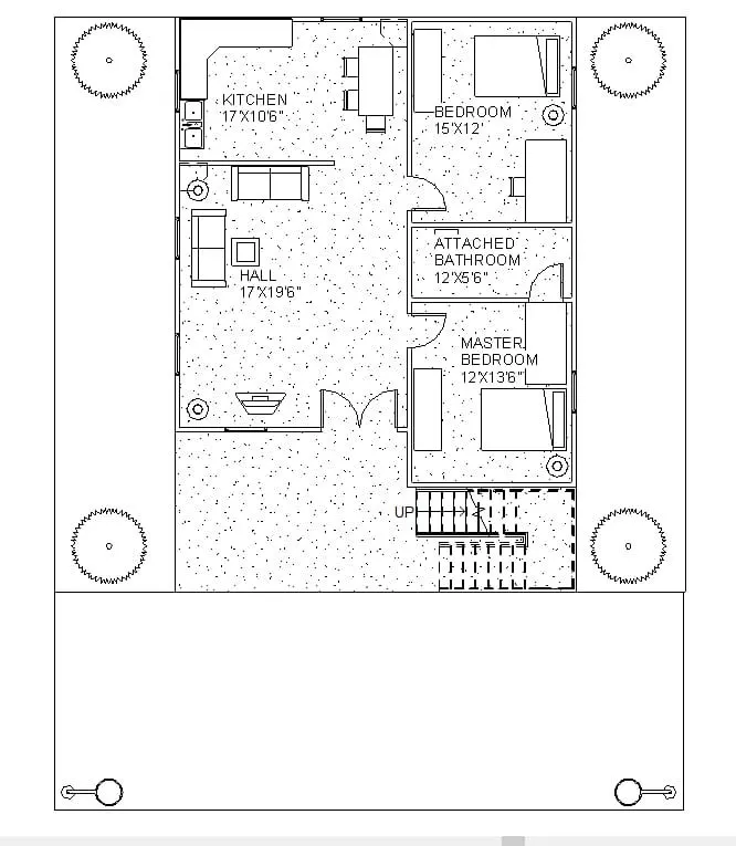
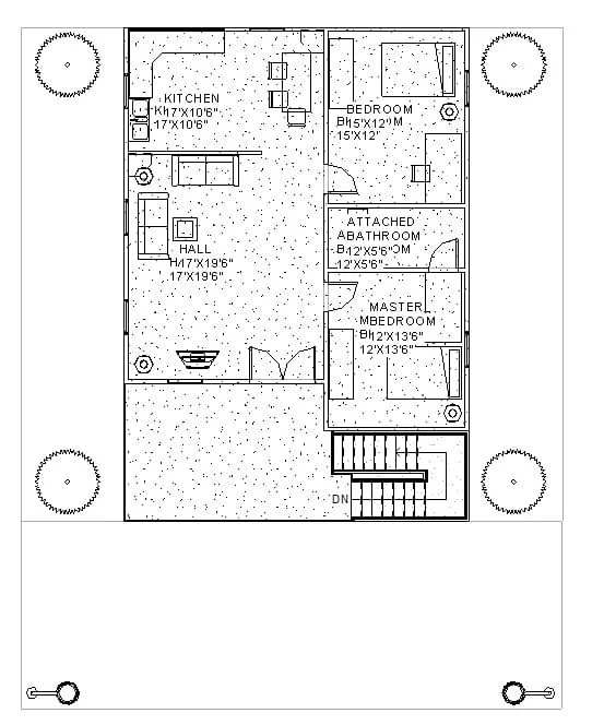
* First we draw the architectural plans of first floor and second floor as shown below.
Step 2:
* Next draw the structural plans of the ground floor and the first floor as shown below.
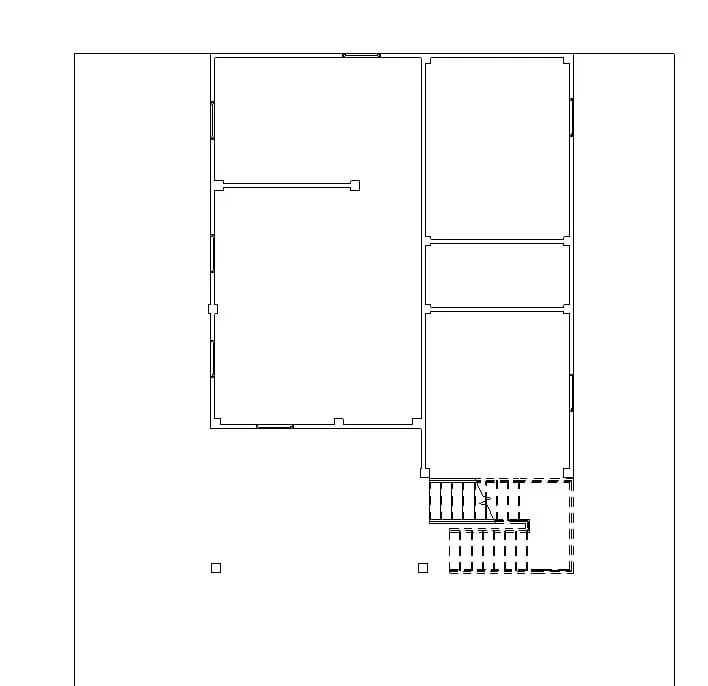
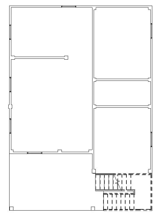
RESULT:
* The plan views for ground floor and first floor has been created.
* Both the architectural and structural view is created.
Q4)
AIM:
To add dimensions to all the walls and floors with reference to the longitudinal and transverse grids created in the projects file.
INTRODUCTION:
* The structural plan view is the default view when you start a new projects using a structural templates.
* Most projects include at least one structural plan. New structural plan views are created automatically as you add new levels to your projects. you can create multiple structural plan view types.
* The floor plan view is the default view in a new architectural projects. most projects include at least one floor plan.
* Floor plan views are created automatically as you add new levels to your projects.
PROCEDURE:
Step 1:
* Here we drawn the longitudinal and transverse grids to the architectural floor plans as shown below.
* And add the dimensions to the architectural plans as shown below.
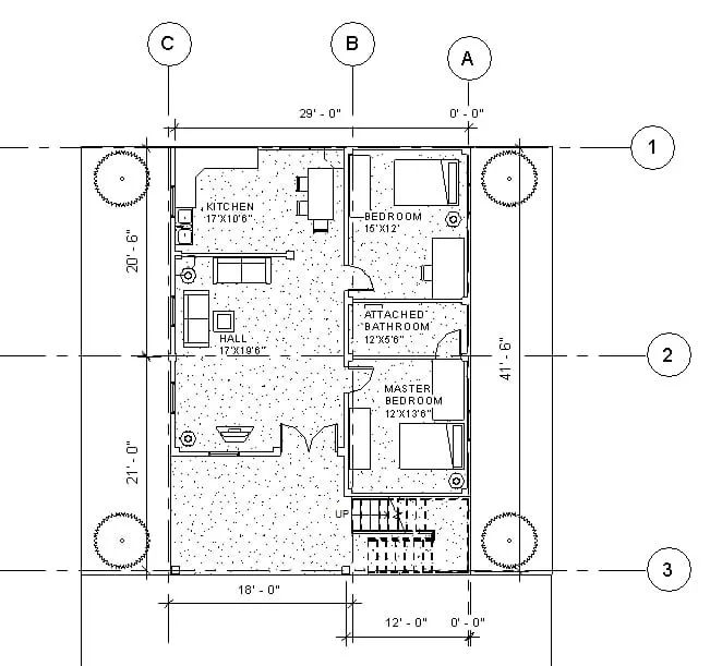
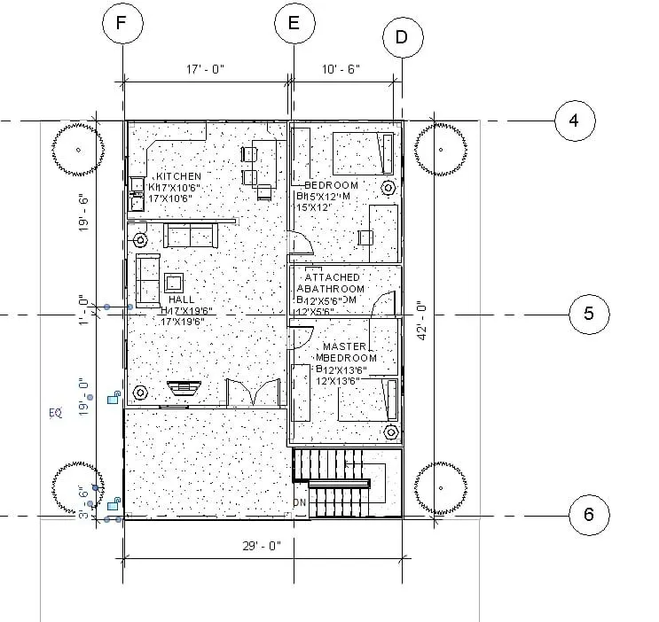
Step 2:
* In structural plan draw the grids and mark the dimensions
* Repeat it for both the levels.
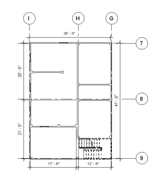
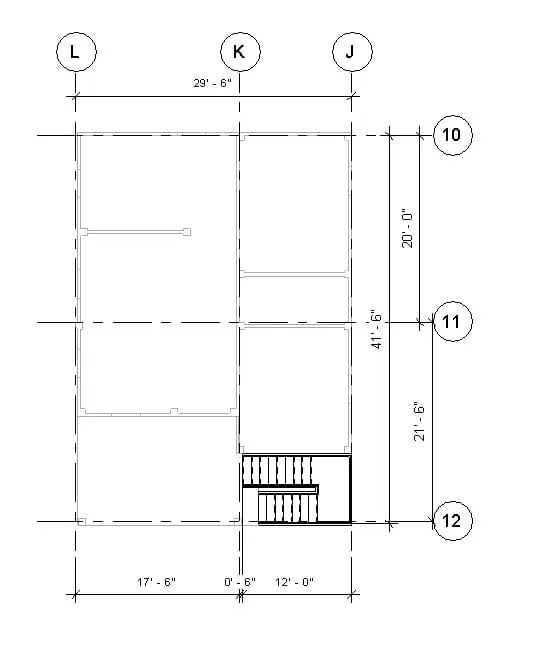
RESULT:
The dimension are added to both the structural and architectural plans.
Q5)
AIM:
To create a sheet template from the view tab and adjust the parameters on the sheet to add appropriate views.
INTRODUCTION:
* Create views on a projects tempate before you start building the model to streamline the projects documention process.
* When creating a projects templates you can include sheets in the templates start with a blank project file and create the standard views and levels that each project should include.
* Leave the views empty but assign standard names to them. to create a standard set of construction documents, create sheets using the desired title blocks
* Add views to the sheets, using the desired viewport templates and view title types.
* Then save the empty projects as a project template.
* When you create a projects using this project template, all of the views and sheets are already created and listed in the project browser.
* As you start to draw the building model in the projects views, the views on the sheets update automatically.
* This technique streamline the projects documentation process and maintains organizational standards.
PROCEDURE:
Step 1:
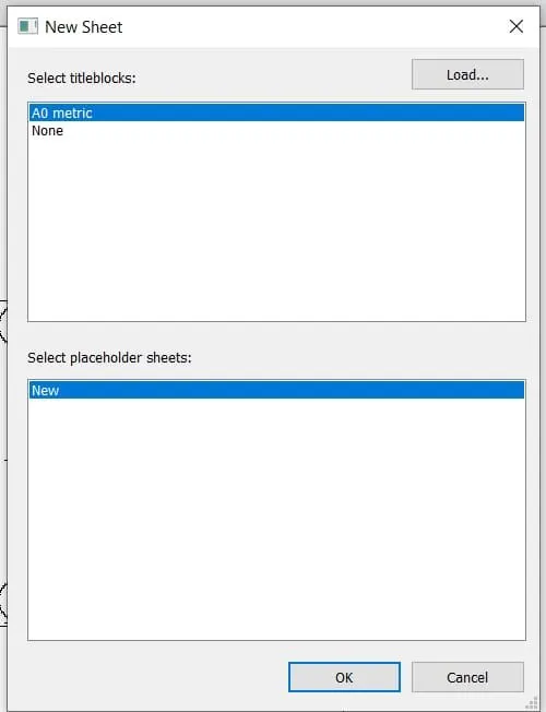
* First we click on the sheet option from the view toolbar, as shown below.
* After clicking the sheet. the new tab will be visible on the screen.
* In that new tab we select the AI metric, then the sheet template will be displayed.
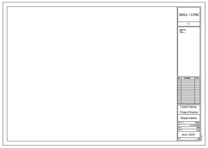
Step 2:
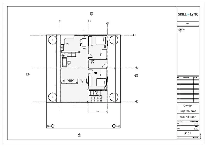
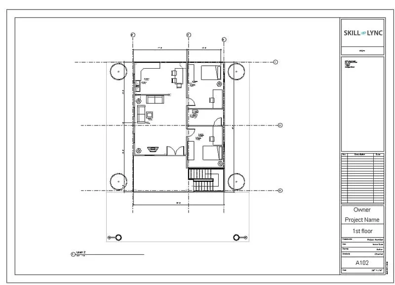
* In the sheet template we insert the ground floor plan and first floor plan seperately.
* Next edit the projects name and the sheet number as shown below.
RESULT:
The sheet template is created from the view tab and adjusted the parameters on the sheet for adding approprite views.
Q6)
AIM:
To create the elevation views, looking at your building from east, north, south, and west using the elevation tab
INTRODUCTION:
* An elevation is a view of a building seen from one side, a flat representation of one view.
* This is the most common view used to desribe the external appearance of a building.
* Each elevation is labelled in relation to the compass direction it faces.e.g looking toward the north you would be seeing the southern elevation of the building.
PROCEDURE:
Step 1:
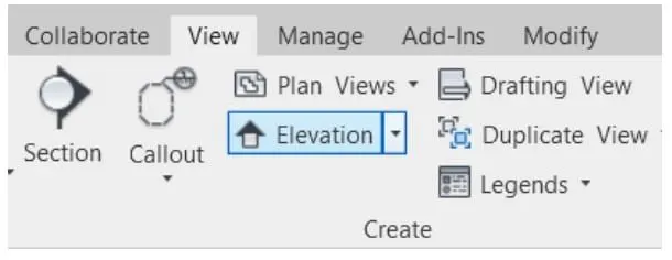
* First we click on the elevation option from the view toolbar, as shown below.
Step 2:
* Next the elevation of east is visible as shown below.

Step 3:
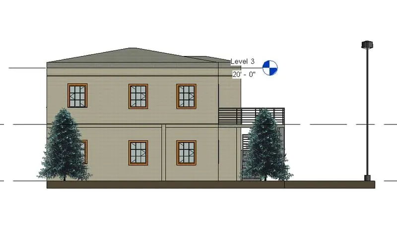
* Elevation view of west is given below.
Step 4:
* Elevation view of north is given below.
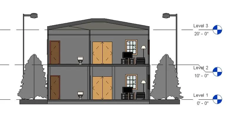
Step 5:
* Elevation view from south is given below.
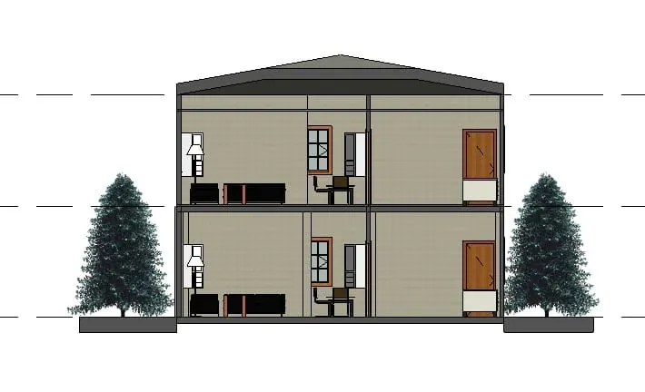
RESULT:
All the elevation views from each direction is shown.
Q7)
AIM:
To produce section cut through each room either cutting across longitudinally or in a transverse direction.
INTRODUCTION:
* Sectional views reveal hidden details in a mechanical drawing.
* These views assume that a cutting plane has removed portion of the object represented by the drawing, displaying the appropriate section of the interior.
* Sectional views are used in engineering and architectural drawings.
* They help civil engineers, architects, and airplane designers communicate their ideas to their peers.
PROCEDURE:
Step 1:
* First we click on the section option from the view toolbar, as shown below.
* Next we produce the section view of the bed room as shown in the below figure.
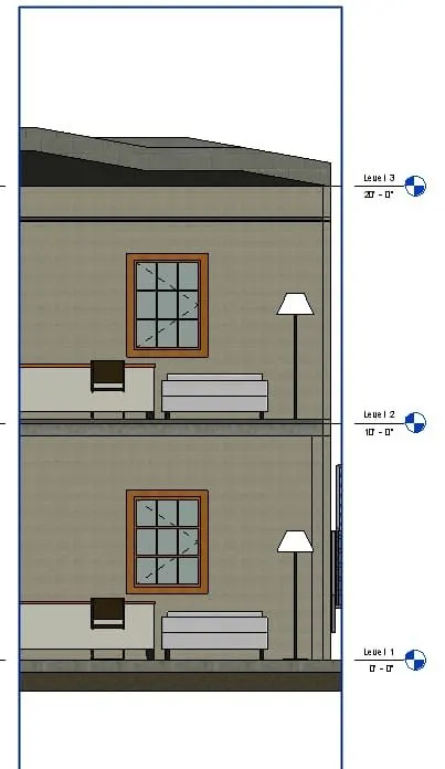
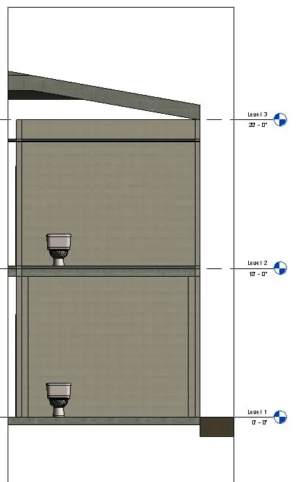
Step 2:
The section view of toilet is given.
Step 3:
The section view of kitchen is given.
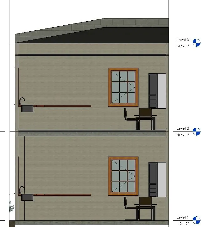
Step 4:
The section view of living room is created and given.
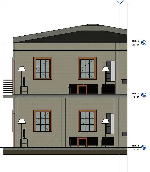
RESULT:
All the section views of each room is created.
Q8)
AIM:
To classify the views, plan views, section views and elevation views to either design or documentation category using properties browser
INTRODUCTION:
* The structural plan view is the default view when you start a new project using a structural template.
* Most projects include at least one structural plan. new structural plan views are created automatically as you add new levels to your projects. you can create multiple structural plan view types.
* The floor plan view is the default view in a new architectural projects. most projects include at least one floor plan.
* Floor plan views are created automatically as you add new levels to your projects sectional views reveal hidden details in a mechanical drawings.
* These views assume that a cutting plane has removed portions of the objects represented by the drawings, displaying the appropriate section of the interior.
* sectional views are used in engineering and architectural drawings
* They help civil engineers, architets, and airplane designers communicate their ideas to their peers.
* An elevation is a view of a building seen from one side, a flat representation of one view.
* This is the most common view used to describe the external appearance of a building
* Each elevation is labelled in relation to the compass direction it faces, eg. looking towards the north you would be seeing the southern elevation of the builing.
PROCEDURE:
Step 1:
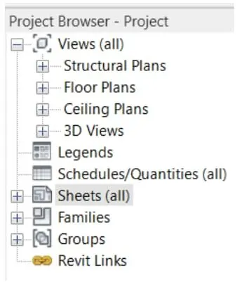
* First we open the pojects browser the views, plari views, section views, and elevation views are visible in that project browser as shown below.
* Next we insert these plans one by one in the sheets separately.
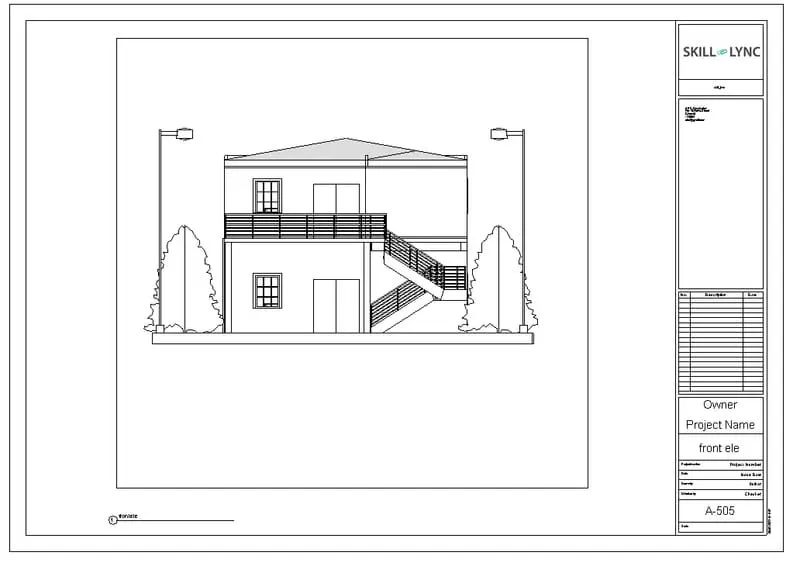
Step 2:
Insert the front elevation in the sheet template
Step 3:
Insert the right side elevation of the building.
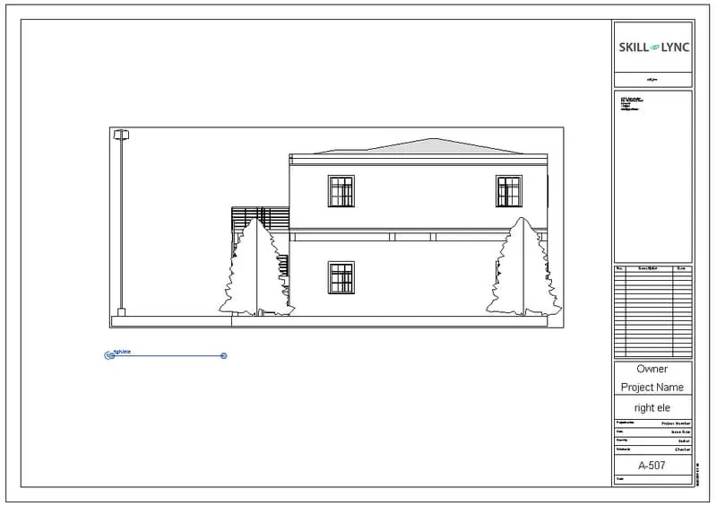
Step 5:
Insert the back elevation of the building.
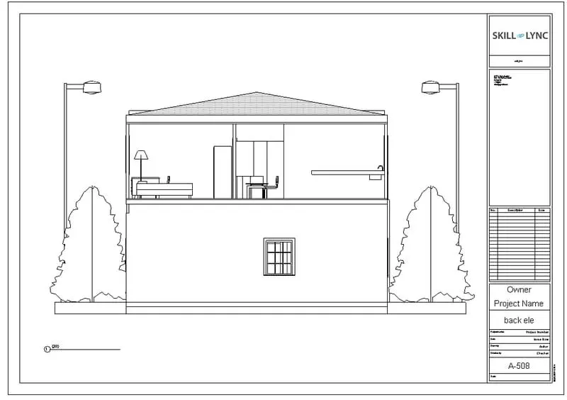
Step 6:
Insert the plan of both ground floor and first floor plan in the template
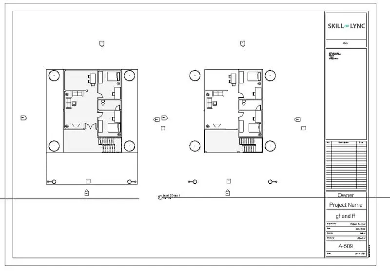
Step 7:
Insert the sectional views of the building in the title blocks.
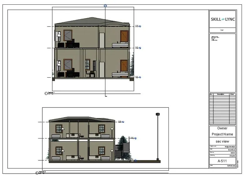
RESULT:
All the views, plan views, elevation views and sectional views are inserted and classified to design category using property browser.
Q9)
AIM:
To create the mutiple sheets and produce the drawings in the sheets, from the given drawing list.
INTRODUCTION:
* Create views on a projects template before you start building te model to streamline the projects documentation process.
* When creating a project template, you can include sheets in the template. start with a blank projecfile, and create the standard views and levels that each project should include.
* Leave the views empty, but assign standard names to them. to create a standardset of contruction documents, create sheets using the desired title blocks.
* Add views to the sheets, using the desired viewport template and view title types.
* Then save the empty project as a project template.
* When you create a projects using this project temlate, all of the views and sheets are already created and listed in the projects browser
* As you start to draw the building model in the projects views, the views on the sheets update automatically. this technique streamline the projects documentation process and maintain organizational standards.
PROCEDURE:
Step 1:
* First we produce the ground floor architectural plan in the sheets template A-101. as shown in the below figure.
Step 2:
The first floor of the architectural plan is created in the template A-102 sheet.
Step 3:
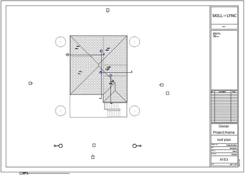
The roof plan is created in the sheet A-103
Step 4:
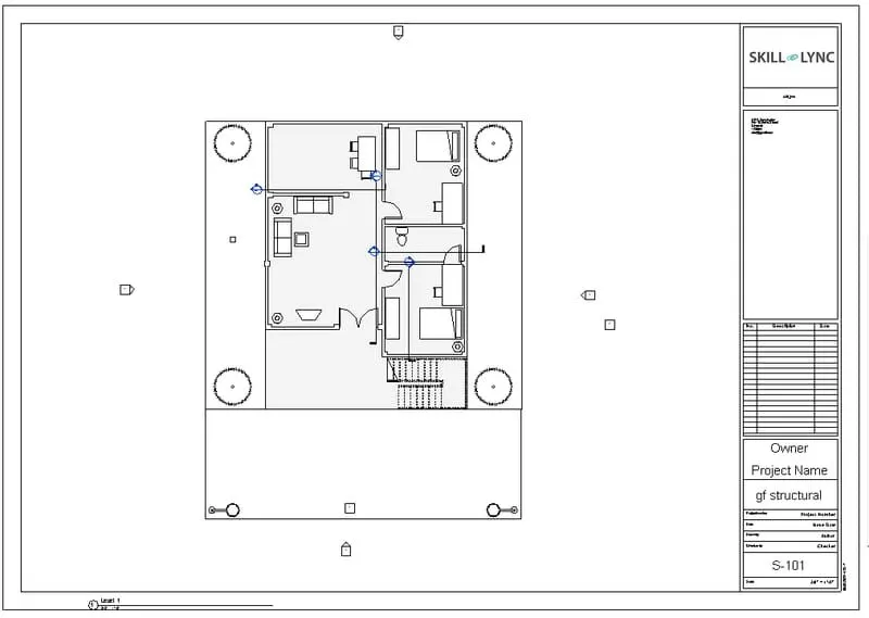
The ground floor structural plan is created in the sheet S 101.
Step 5:
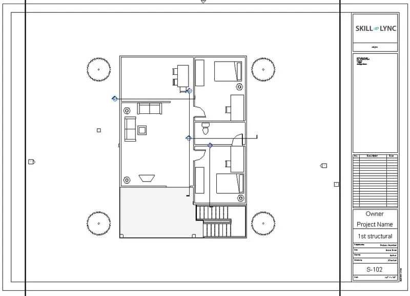
The first floor structural plan is created in the sheets S 102.
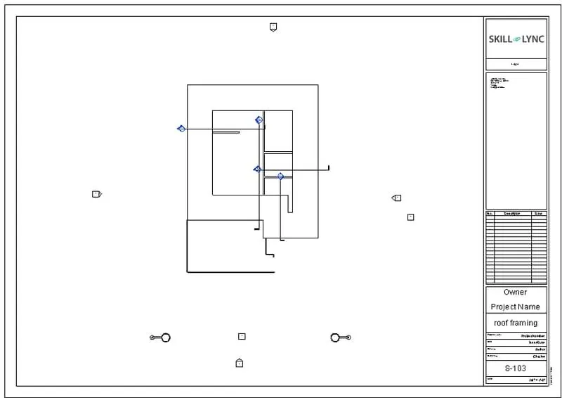
Step 6:
The roof framing plan is inserted in the sheet S 103.
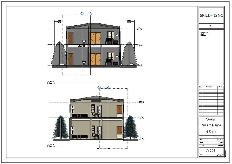
Step 7:
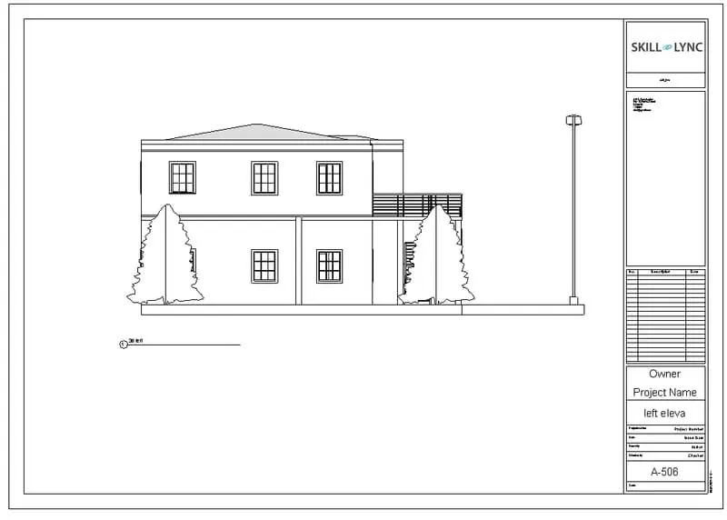
The north south elevation views are inserted in the sheet A 201.
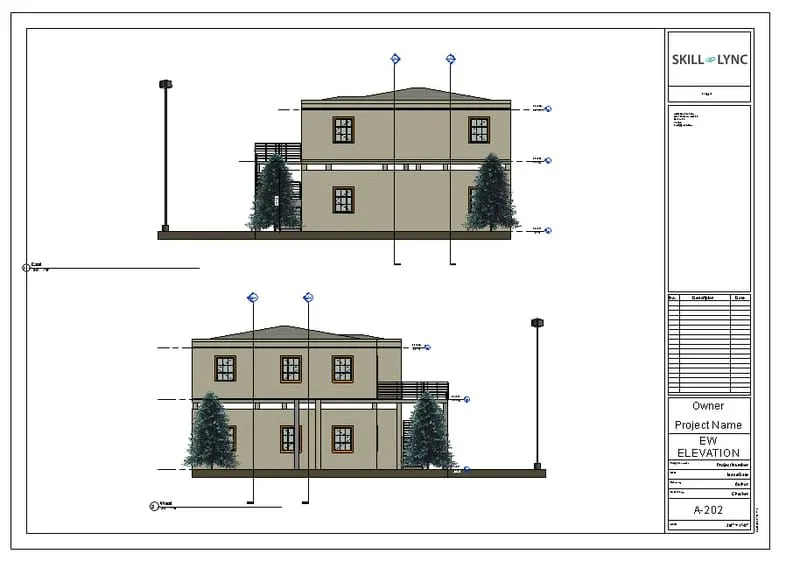
Step 8:
The east west elevation views of the building is inserted in the sheet A 202.
RESULT:
Thus multiple sheets are created and produced the drawings sheets as per the requirement successfully.
Q10)
AIM:
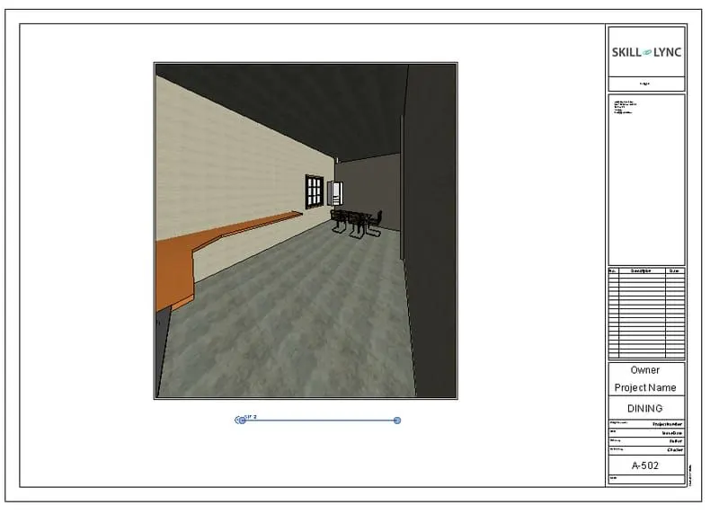
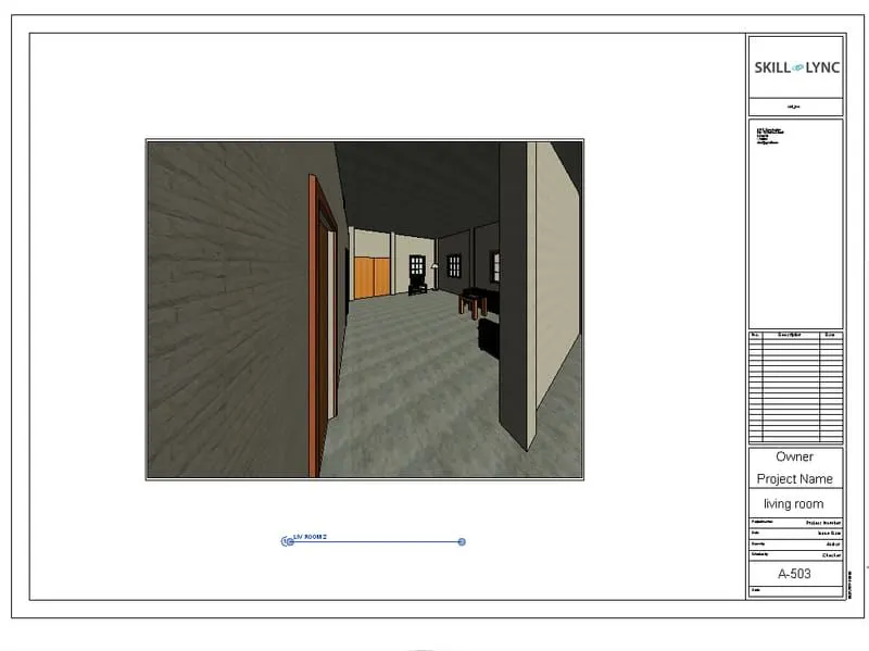
To create a camera- specific view or a 3D view in living room, dinning room and bedroom in the sheets separately.
INTRODUCTION:
* Camera views are really useful in revit.
* They allow us to view what we would actually see if we were standing at any given locaion in our design.
* This can be invaluable for both understanding and communicating the nature of a space before we go to the expensive lengths of actually constructing it for real.
PROCEDURE:
Step 1:
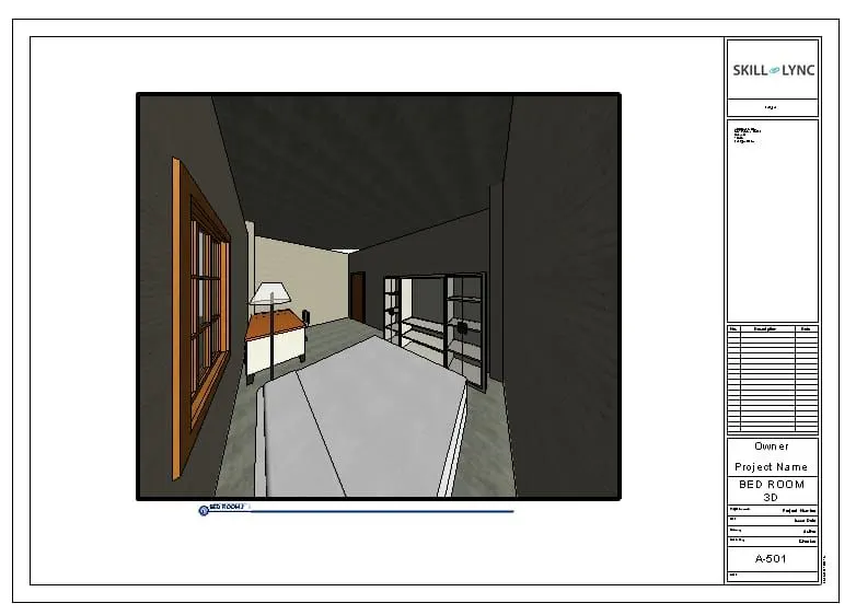
* First we take the sheet and name it as A-501.
* Next go to the floor plan and place the camera in the bedroom, and the camera view of bed room will be shown below.
Step 2:
* Create a sheet and name it A-502.
* Go to the floor plan and place the camera in the dinning room
* The created view in presented in the sheet A-502.
Step 3:
* Create a sheet and name it A-503.
* Go to the floor plan and place the camera in the living room
* The created view in presented in the sheet A-503
RESULT:
The created camera views are presented in the sheet seperately successfully.