3D Creation of Ceiling, Roof, Architectural plan, Structural plan, Sectional view, Elevation view and Camera specific view for a house plan using REVIT
1
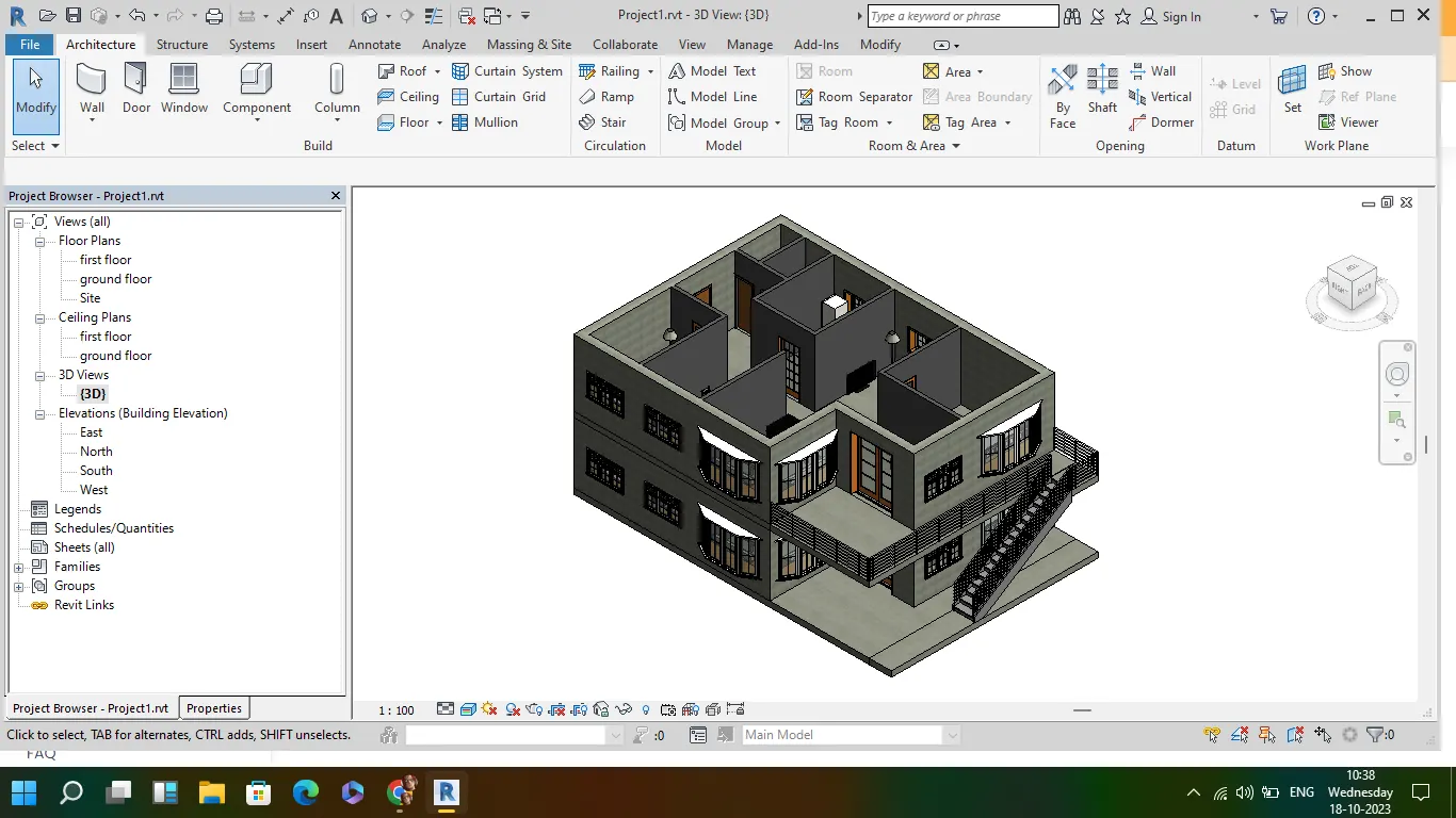
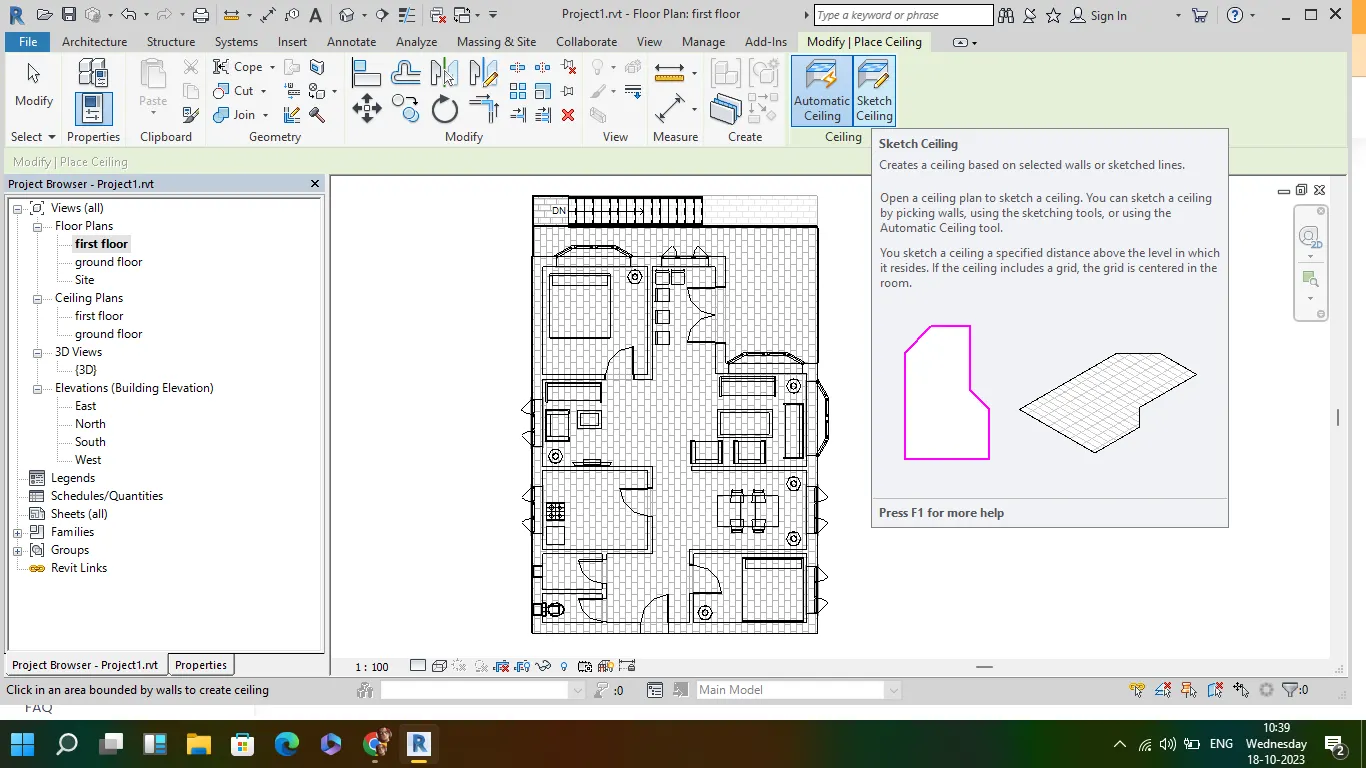
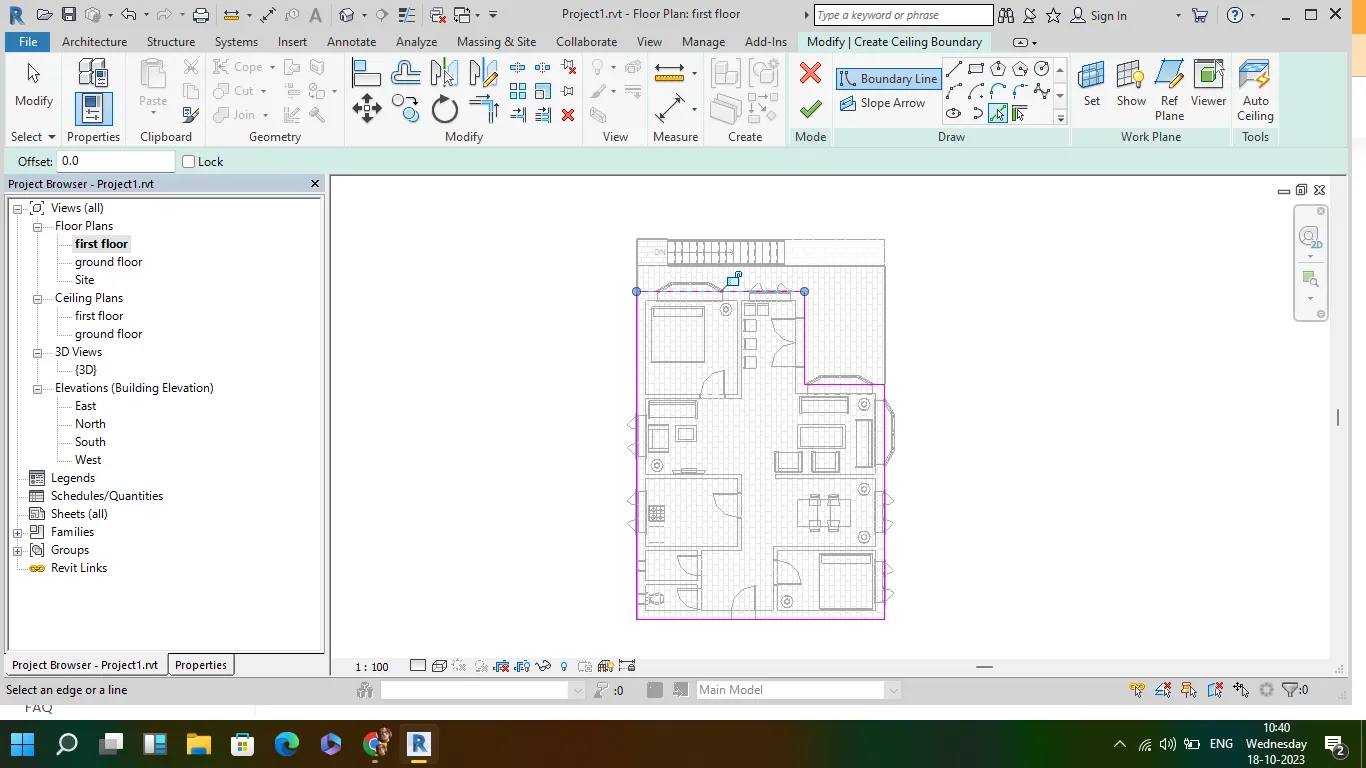
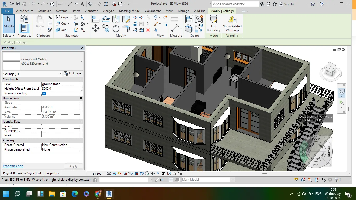
AIM: To create the ceiling from the architecture tab above the walls at the first-floor level
- open revit file from week 3 and go to architecture toolbar
- go to ceiling tab and select pick up lines
- select outer most wall lines and create ceiling. A ceiling is created
2
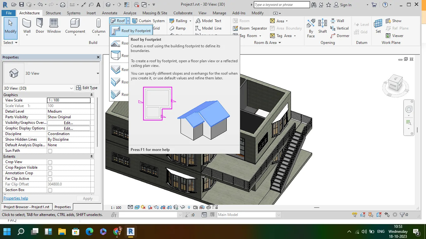
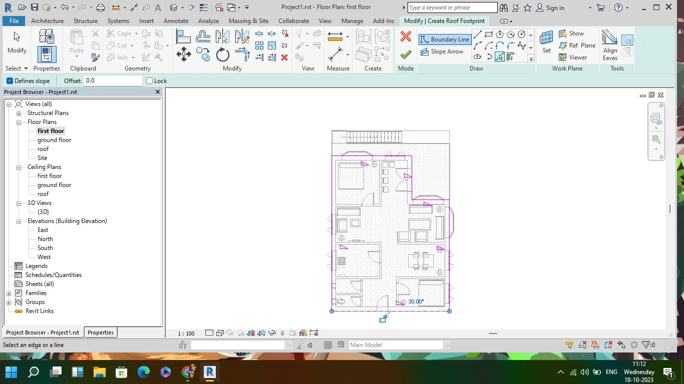
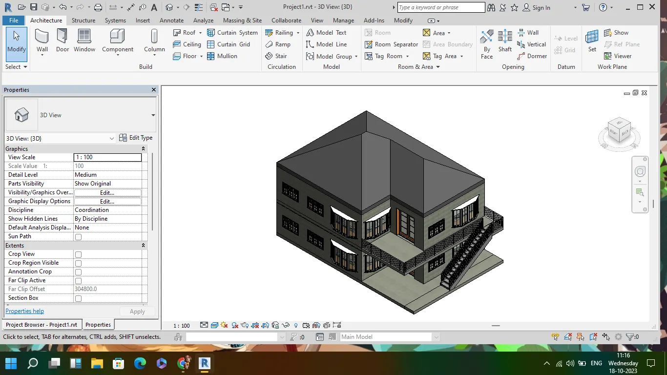
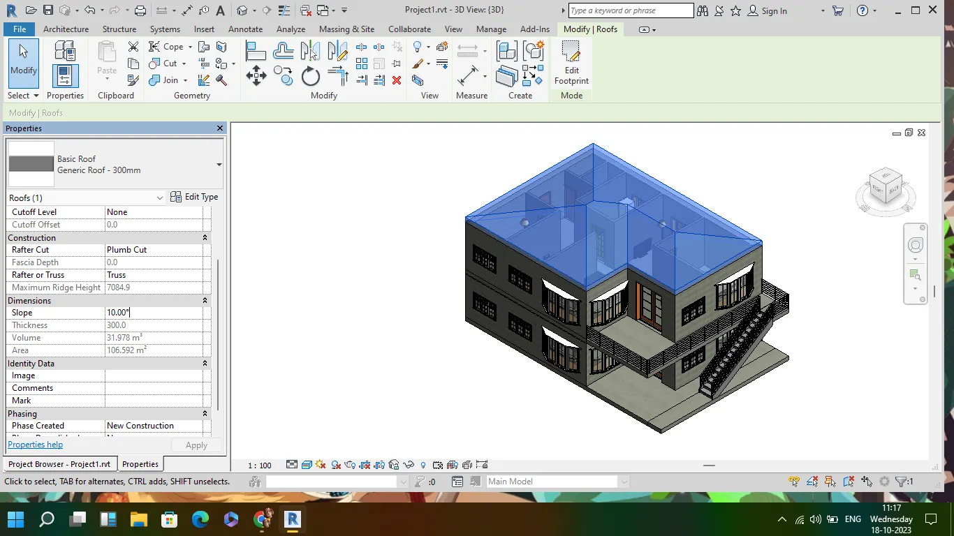
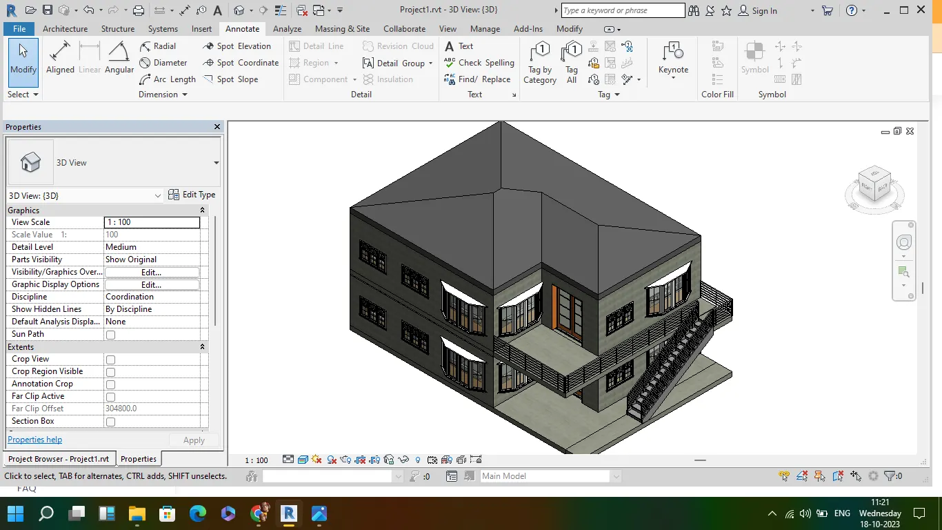
Aim: To model a roof above the ceiling by selecting the footprints of the ceiling. Using the adjustment toolbars appearing on-screen adjust the roof slope to 10 degrees
- go to arch tab and select roof
- select the level of roof in the project browser
- select roof by footprint and select pickup lines and choose the outermost lines of wall
- create the roof and select the roof and go to property browser, select slope and change the slope to 10 degree
3
Aim:To create plan views for ground floor level and first-floor level including all the walls, floors, and components. Separate them to
architecture and structural plans
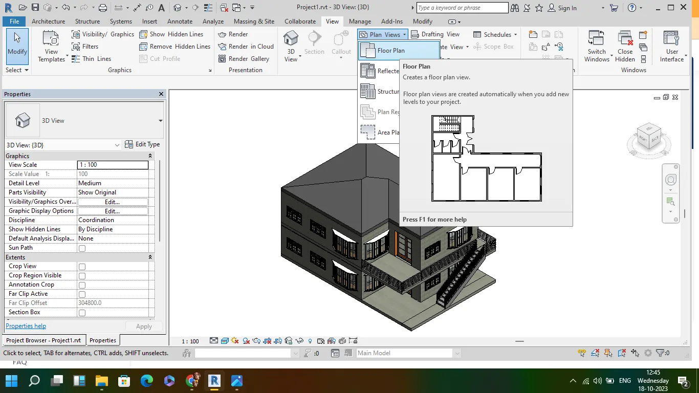
- Go to view tab and to plan views
- here choose floor plan and select ground floor and first floor
- the architecture plan of both floor is created
- select structural plan of both floor from the plan views
- the structural plan of both floor is created
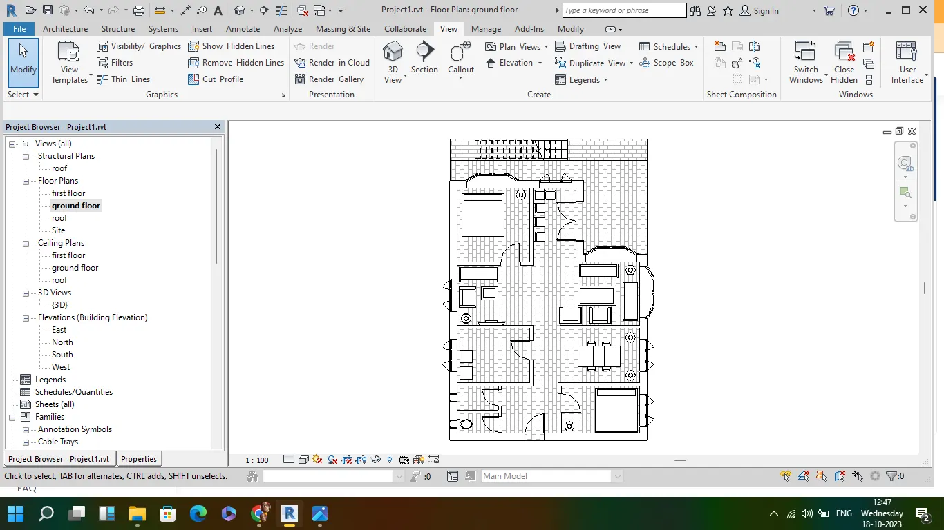
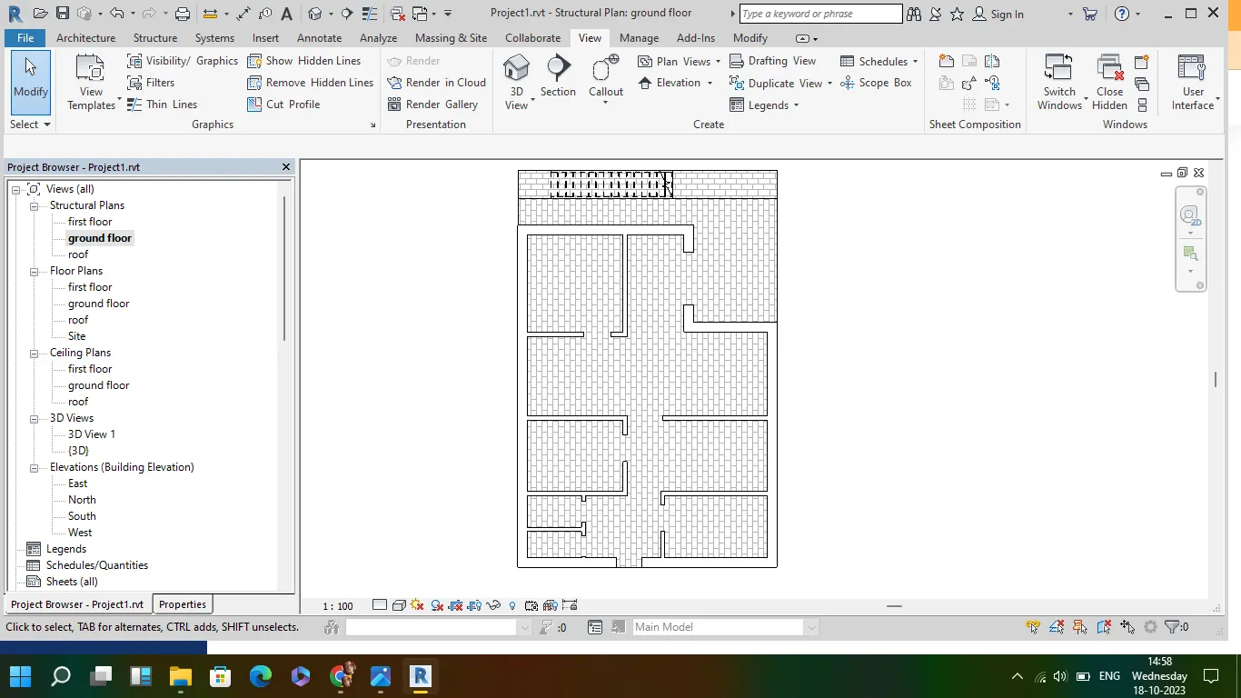
- in arch plan we able to see all the furniture,door,window along with all structural elements
- in structural plan only structural elements like walls,floor,stairs are visible
4
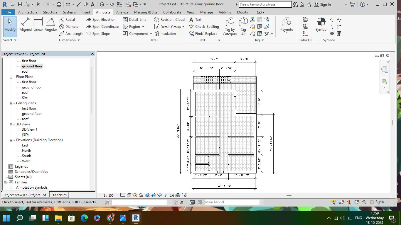
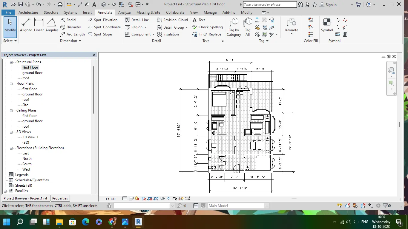
Aim: Using annotate toolbar add dimensions to all the walls and floors with reference to the longitudinal and transverse grids created in the project file
a. The architecture plan dimensions include details on where the components are placed within the buildings with relation to grids. Overall dimensions are sufficient for architecture plans
b. The Structure plan dimensions must include details on the position of all the walls and interior walls with reference to grids. Locate all the framing components of the building with reference to a fixed point using Structural plans
- go to annotate tool bar and slelect alligned
- select ground floor and first floor of structural plan from project browser
- choose eithier center to center of wall or end to end and start adding dimensions
- slelect floor plan from project browser and dimensions to both first and ground floor plan
- add dimensions in both lateral and transverse direction in between external wall and partition wall
5
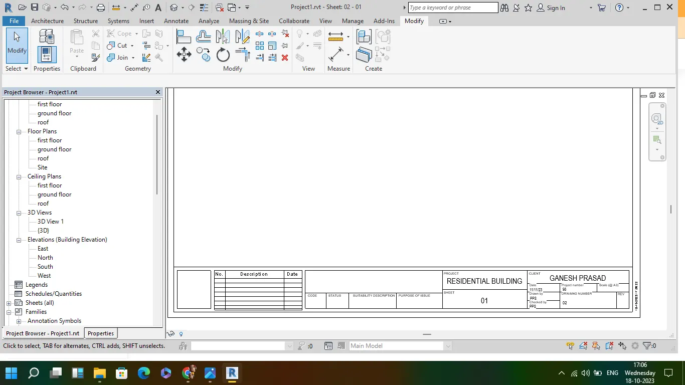
AIM: To create a sheet template from the view tab and adjust the parameters on the sheet to add appropriate views
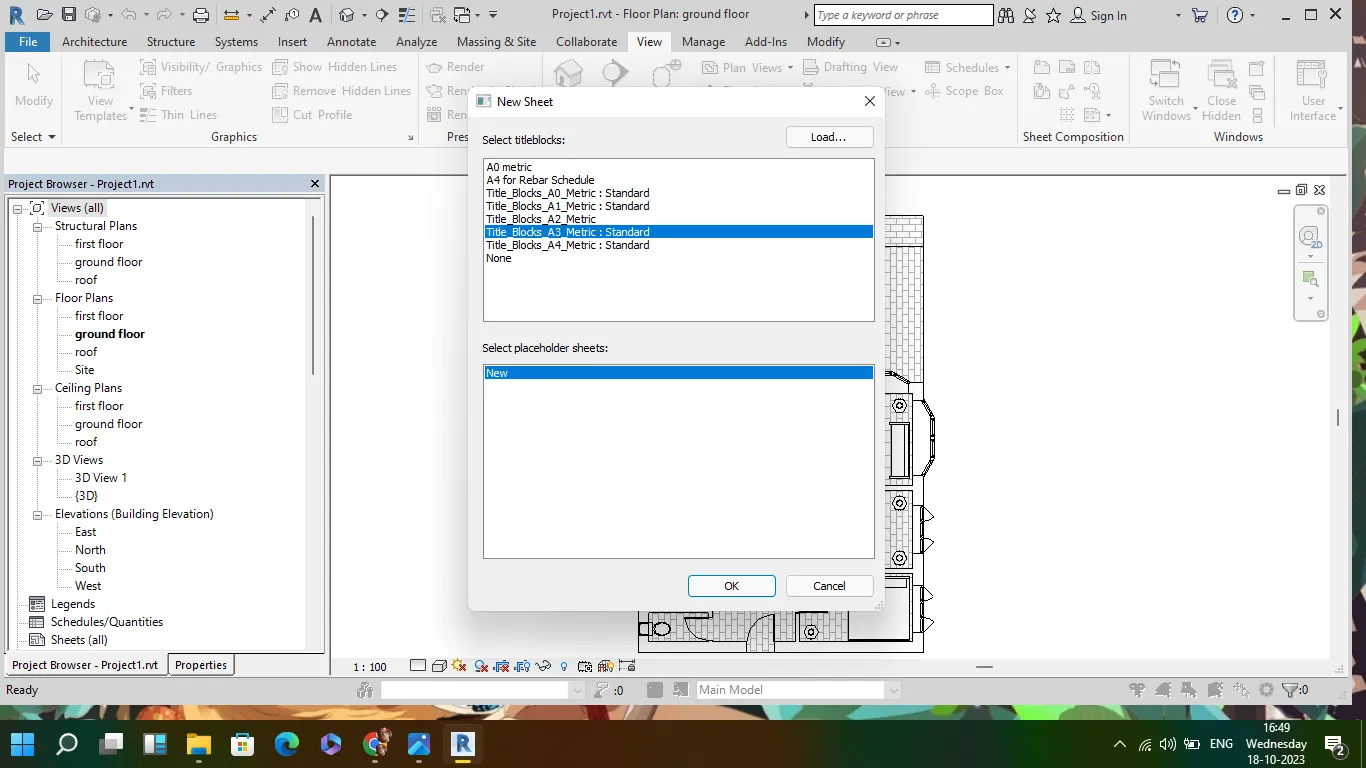
- go to view tab and select sheet
- select the required size of sheet
- create new sheet and double tap on the name of sheet and add the required name , the changed name is directly displayed in project browser
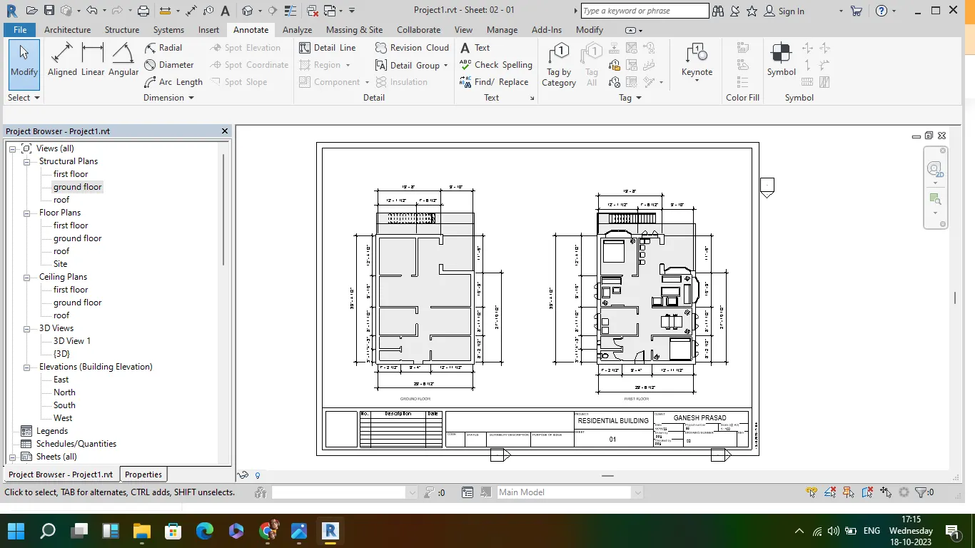
- drag the structural and floor plan from project browser to sheet, so that a the plan can be added to sheet
- adjust the size of plan using scale in property browser
6
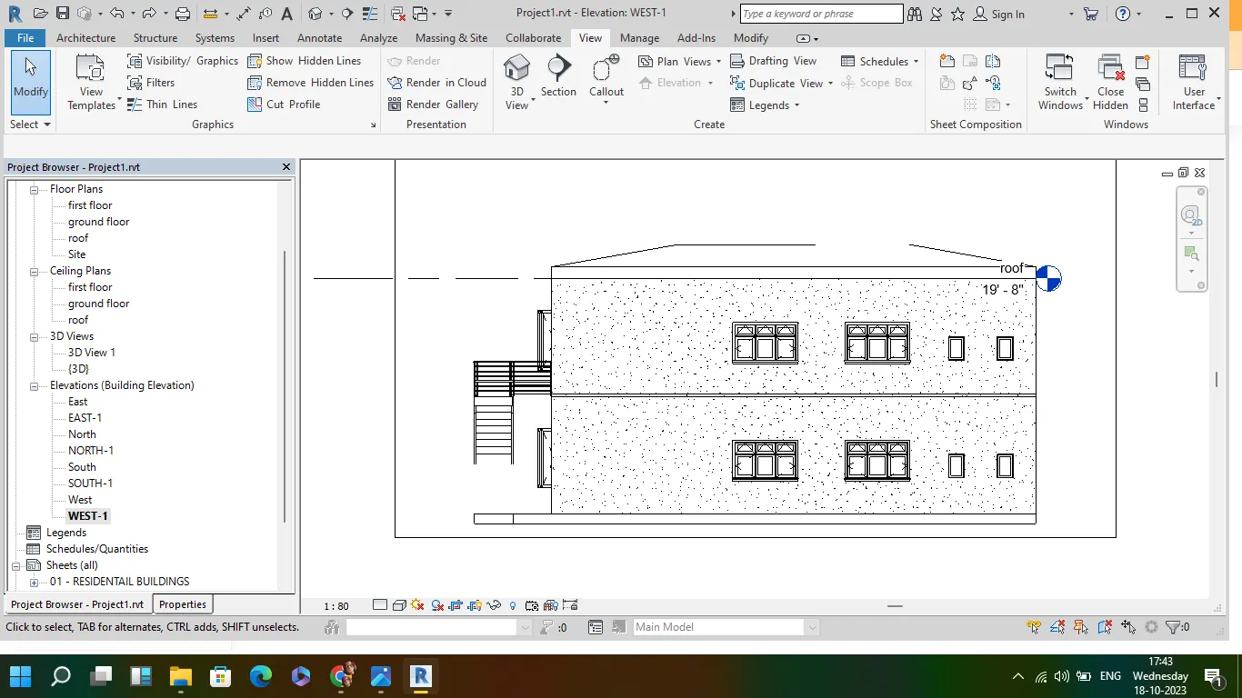
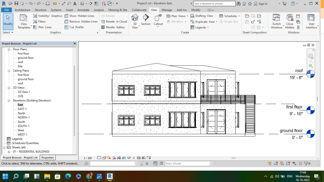
Aim:Using the elevation tab
To create the elevation views, looking at your building from East, North, South, and West
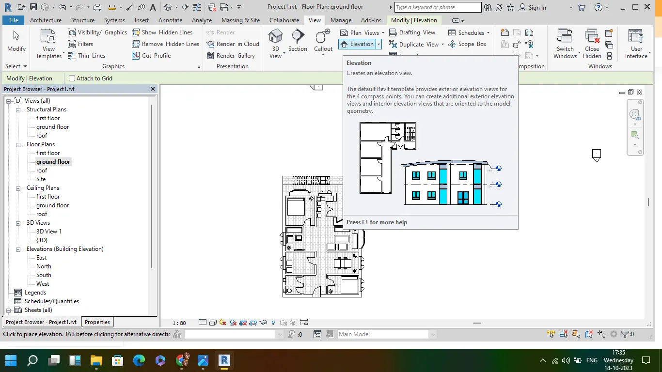
- go to view from the toolbar and select elevation
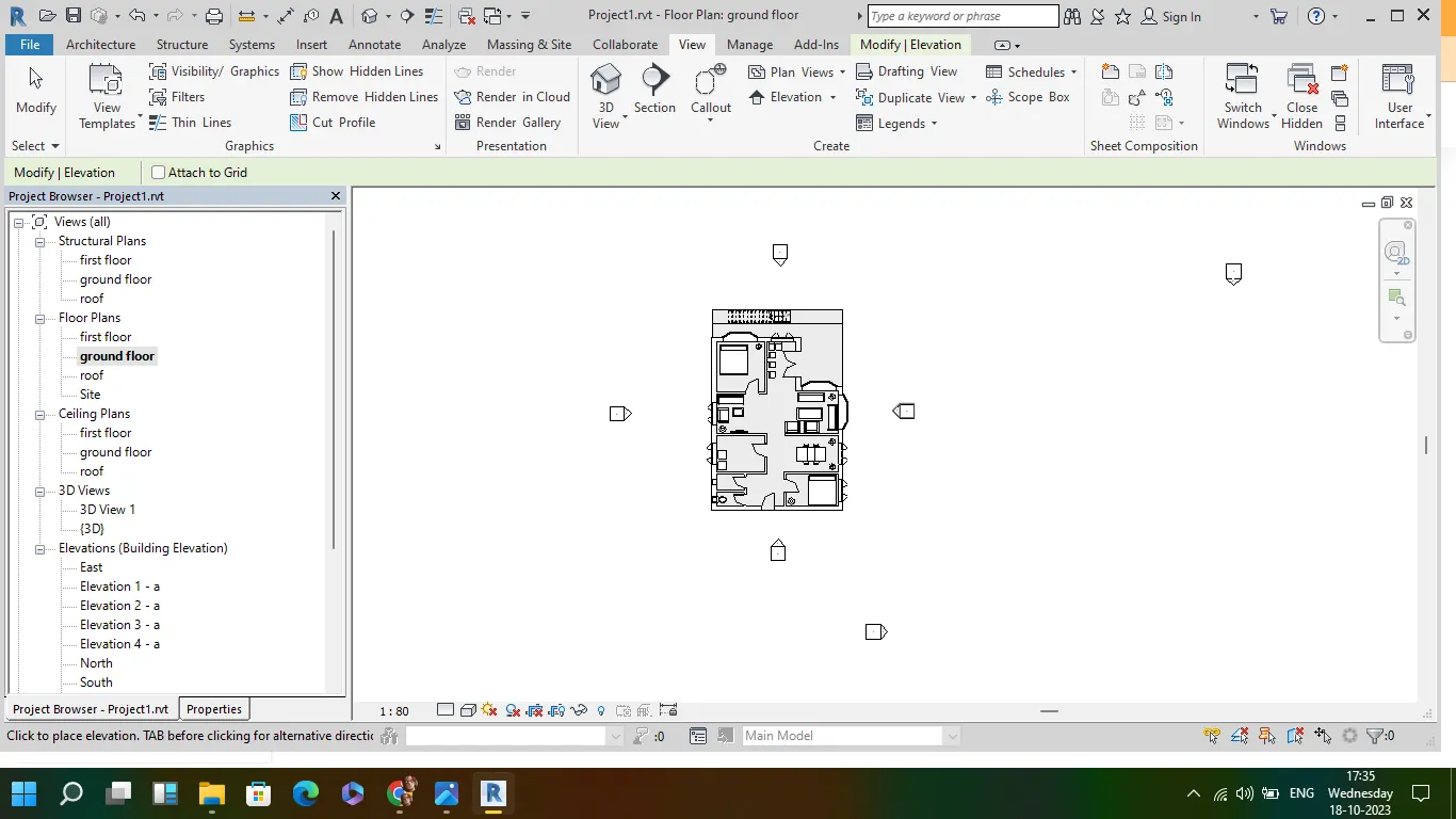
- add the elevation, to required positions of the drawing
- rename it to east west north and south
- click on the each elevation to see the drawing from required elevation
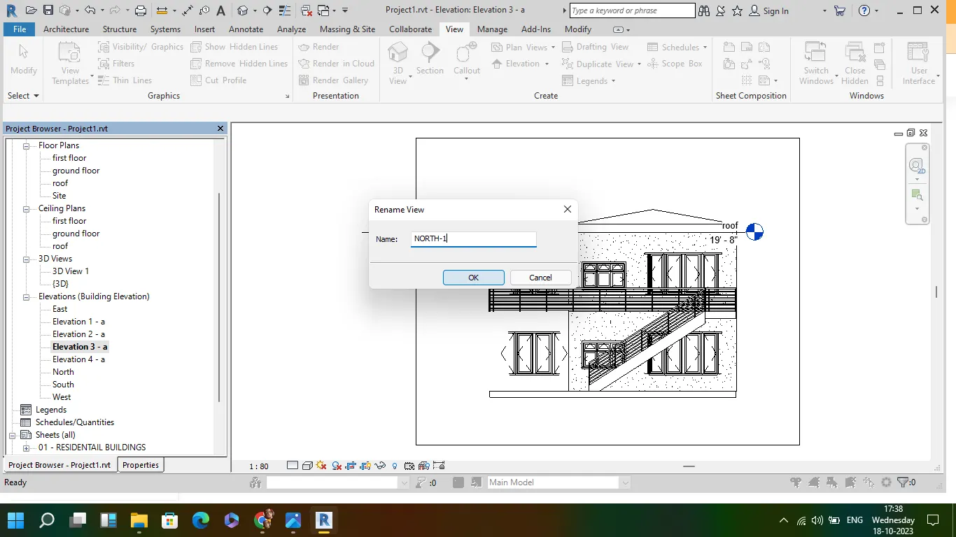
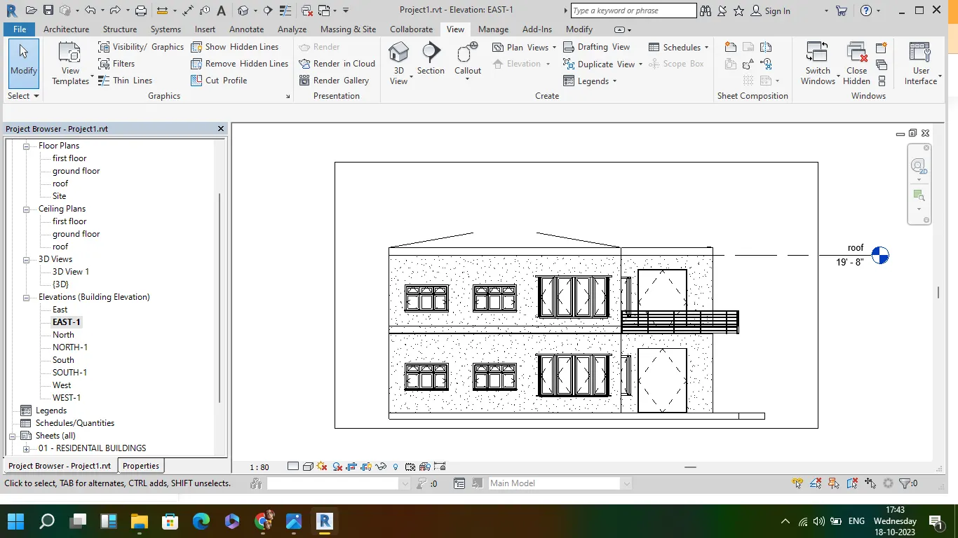
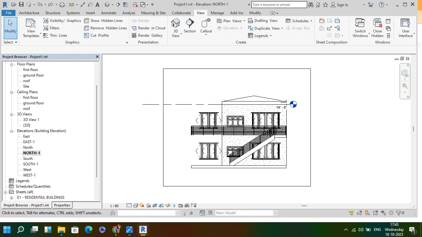
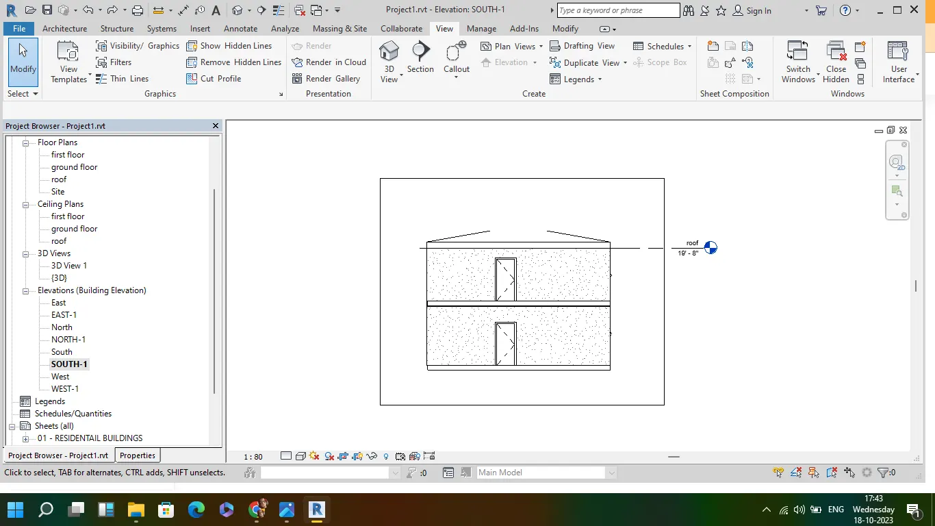
7
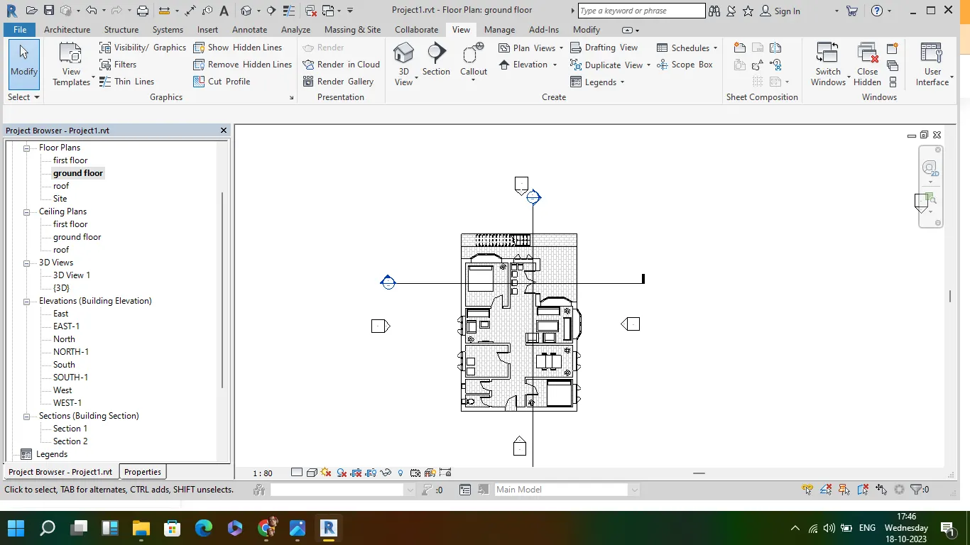
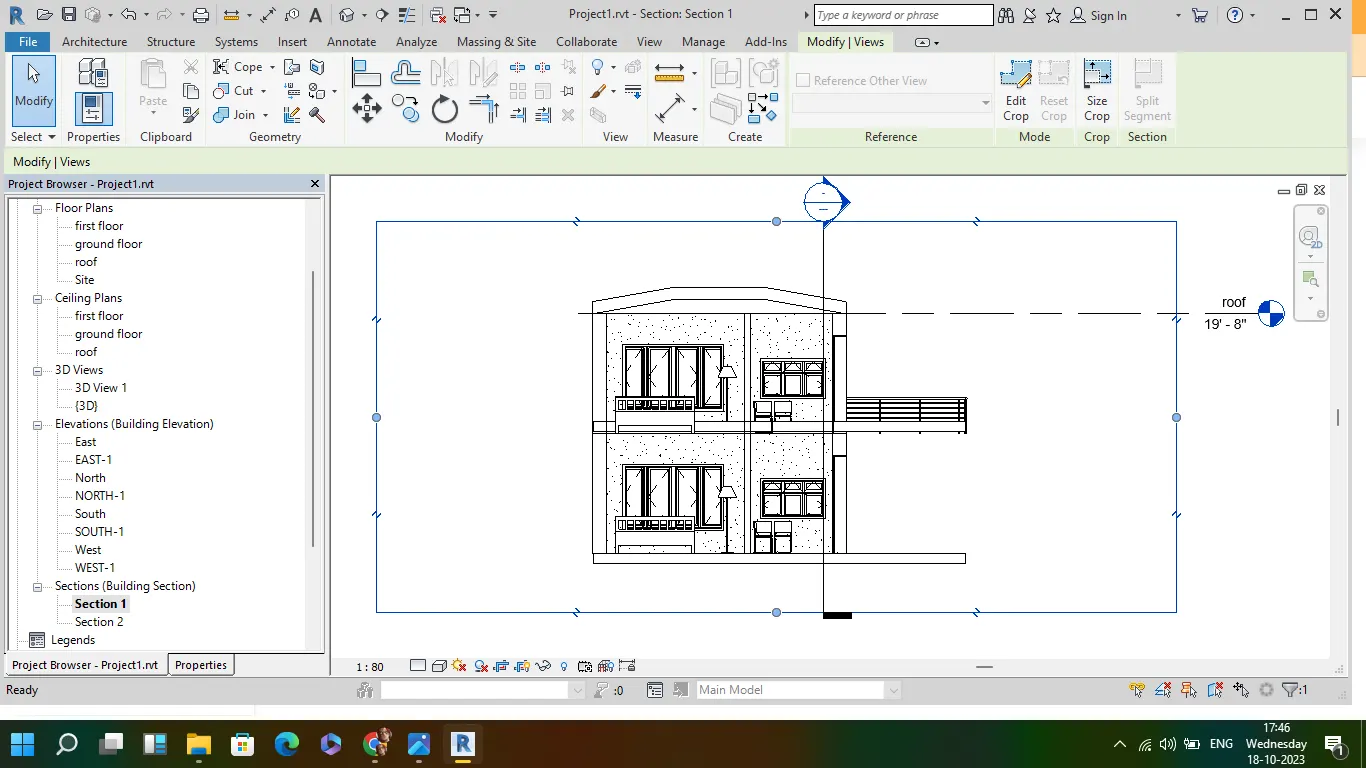
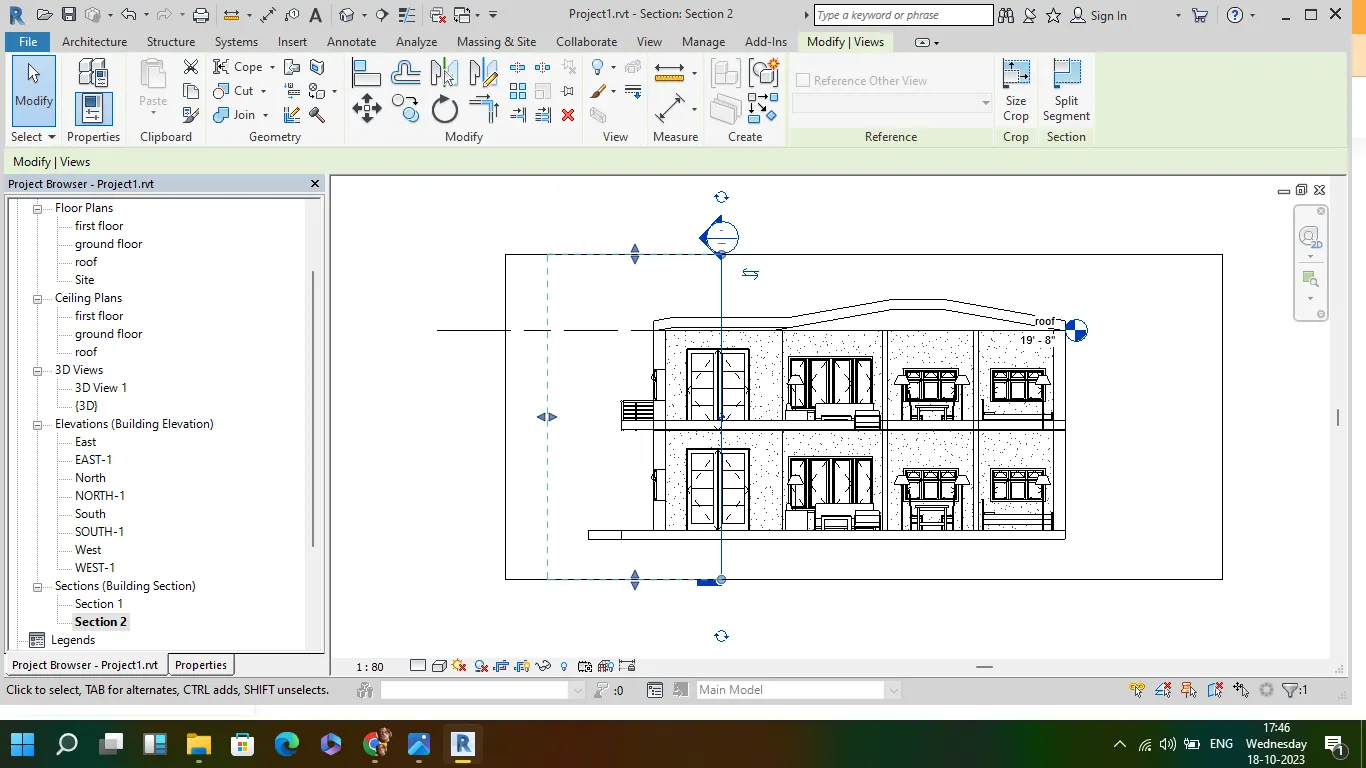
Aim: To produce section cut through each room either cutting across longitudinally or in a transverse direction
- go to view from the tool bar and select section
- cut the required section of either room or entire building in transverse and longitudinal direction
- go to each section from the project browser to see the cross section dia of the building
8
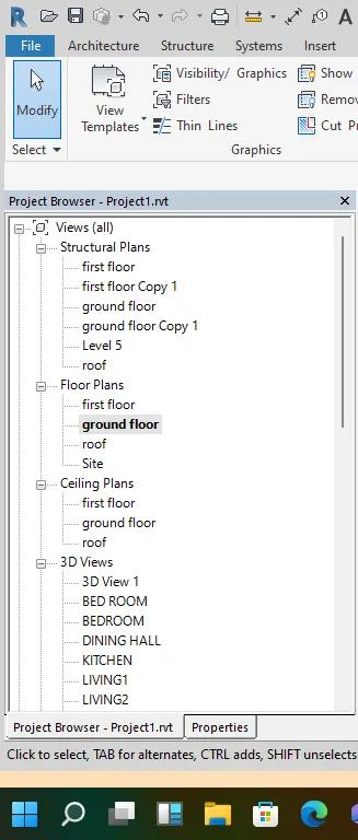
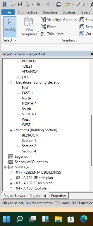
To classify the views, Plan Views, Section Views, and Elevation views to either Design or Documentation category using Properties browser
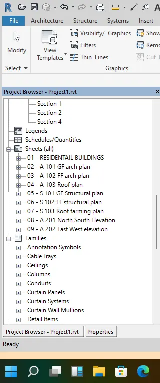
- each views created in drawing is directly named in project browser
- if structural plan created each floor plan is shown in project browser
- if 3D view created each created views can be seen in project browser
- just by clicking over the views, required views can be obtained
9
AIM:
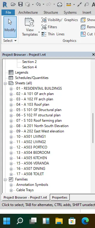
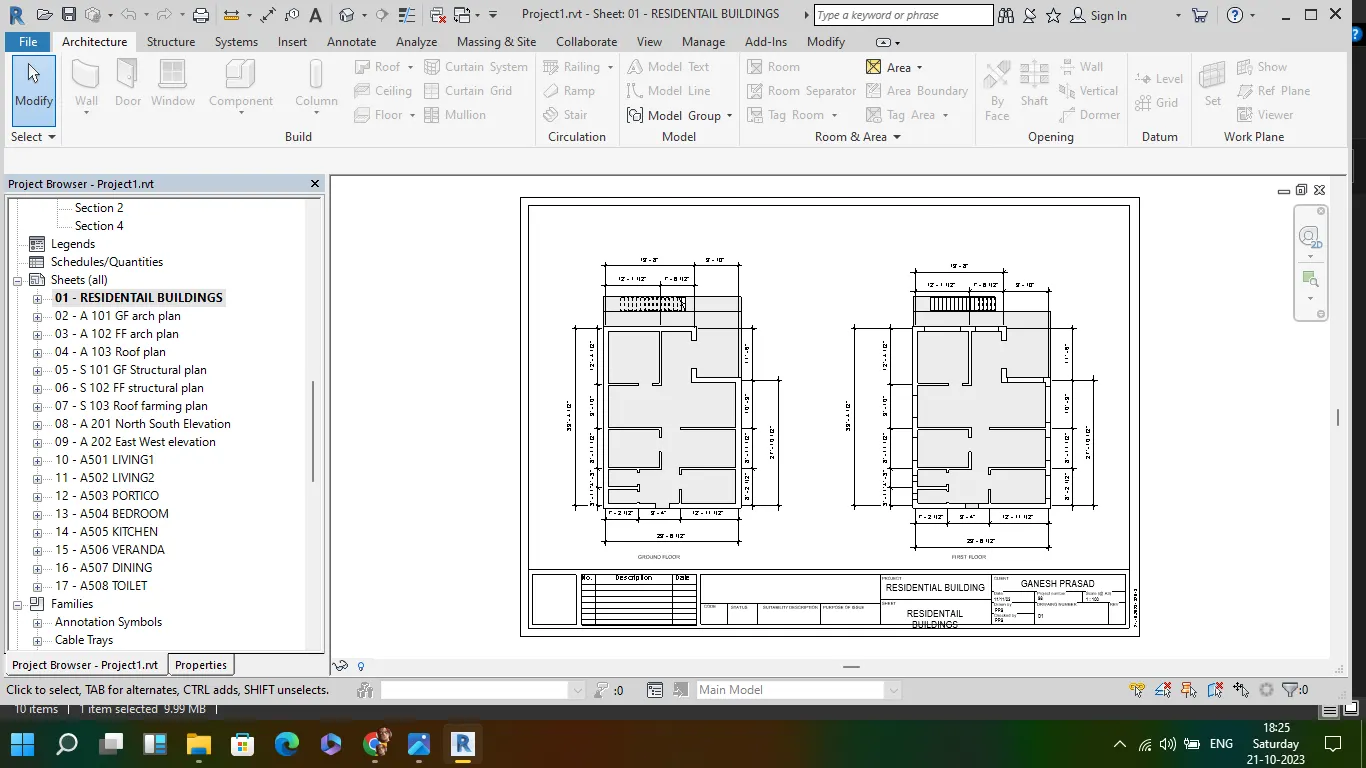
Using the sheet template produced create multiple sheets as follows
a. A 101- Ground Floor Architecture Plan
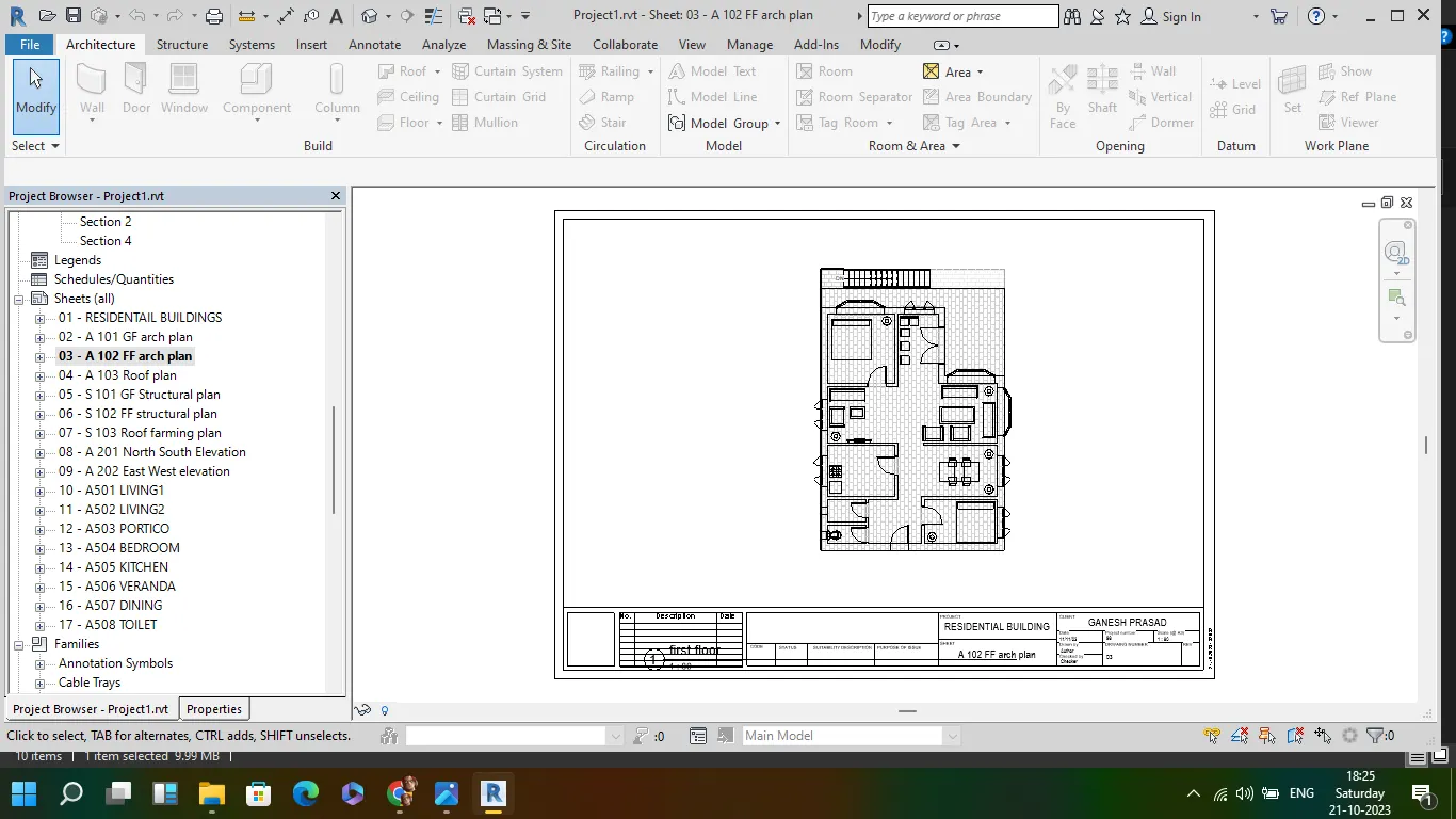
b. A 102- First Floor Architecture Plan
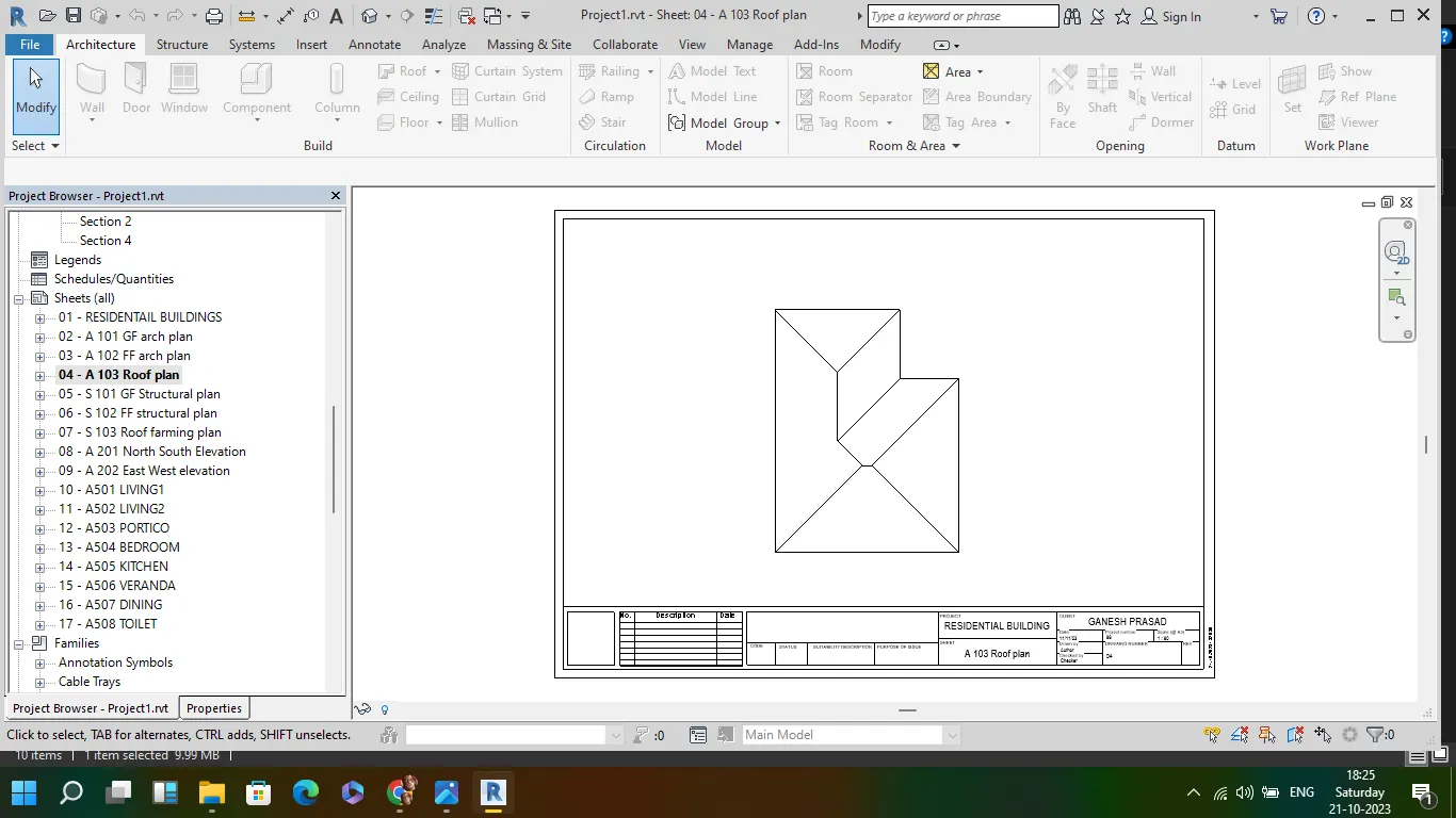
c. A 103- Roof Plan
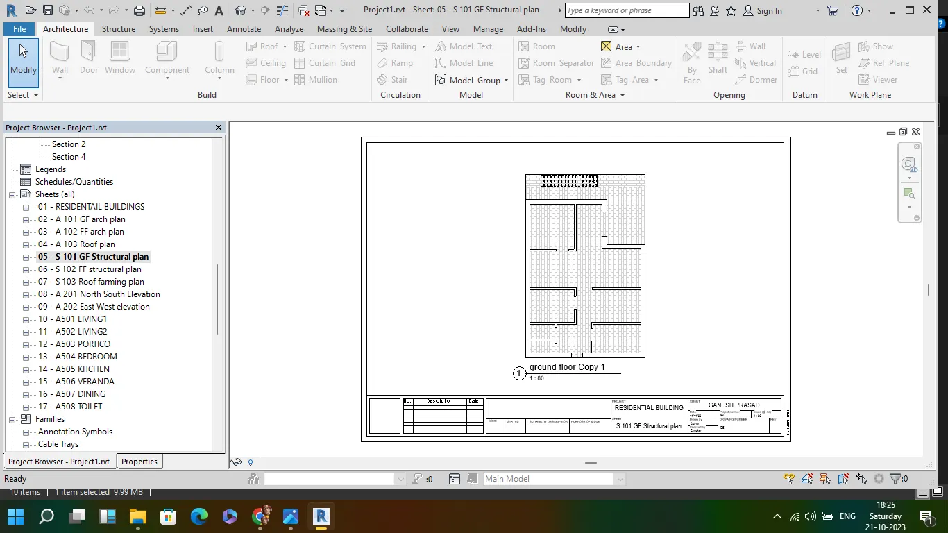
d. S 101- Ground Floor Structural Plan
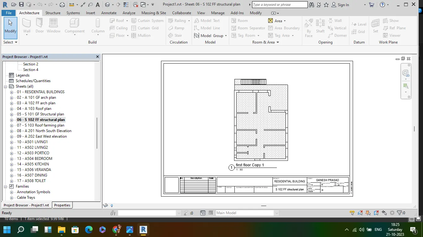
e. S 102- First Floor Structural Plan
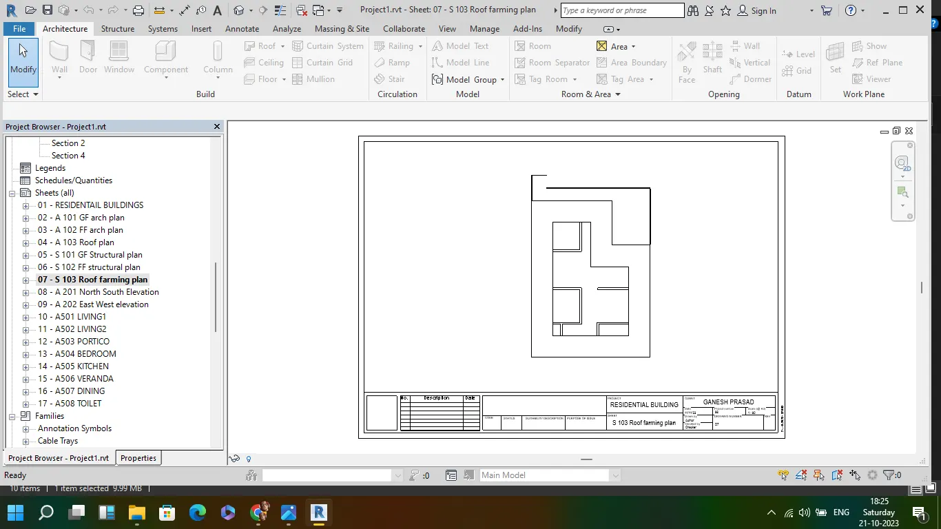
f. S 103- Roof Framing Plan
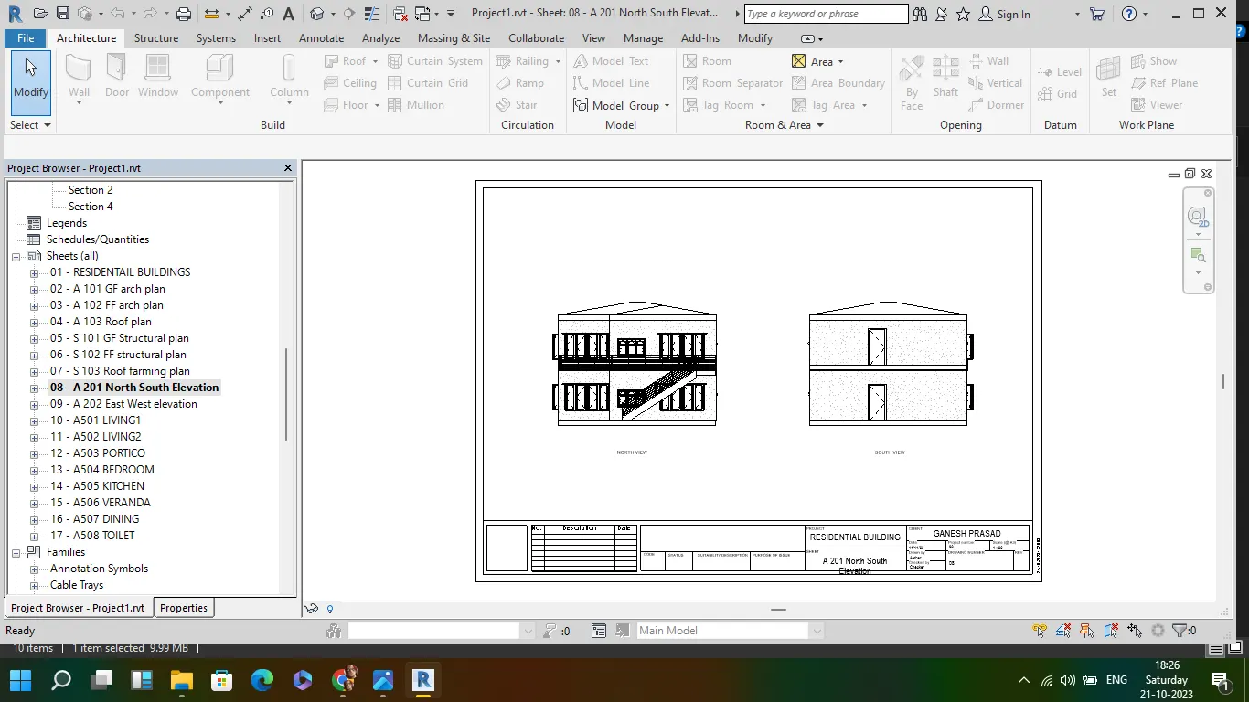
g. A-201- North-South Elevations
h. A-202- East-West Elevations
- go to view tab and create new sheets and rename it as given in challenge
- like A 101, A102 and soo on
- in each sheet template go to project browser and drag the required views in to the sheet and adust the size using scale from the property browser
- each template is created and the created sheet templates will be visible in the project browser

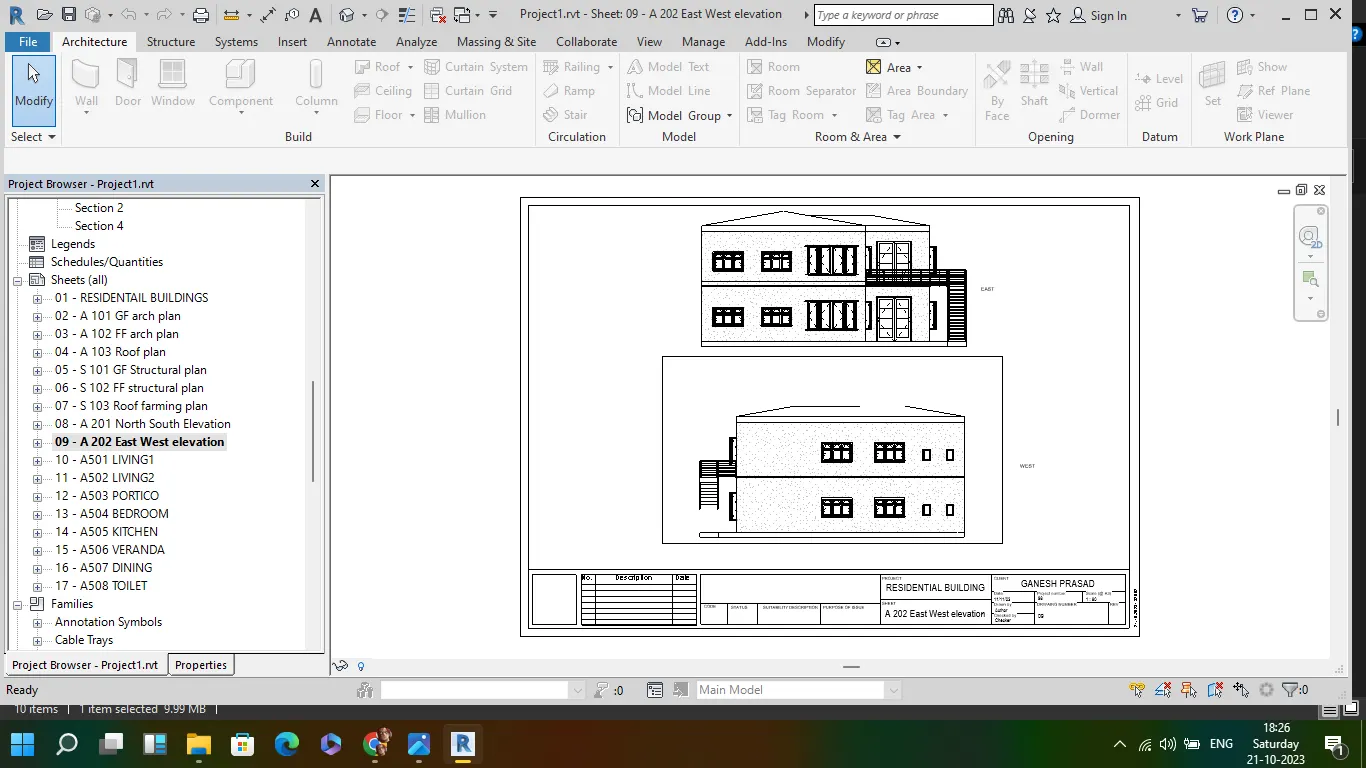
10
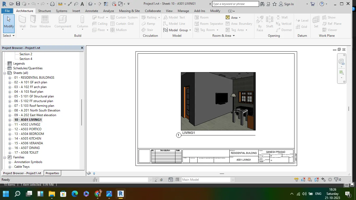
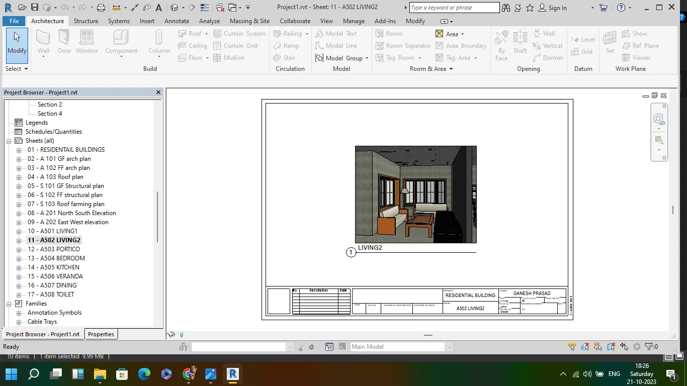
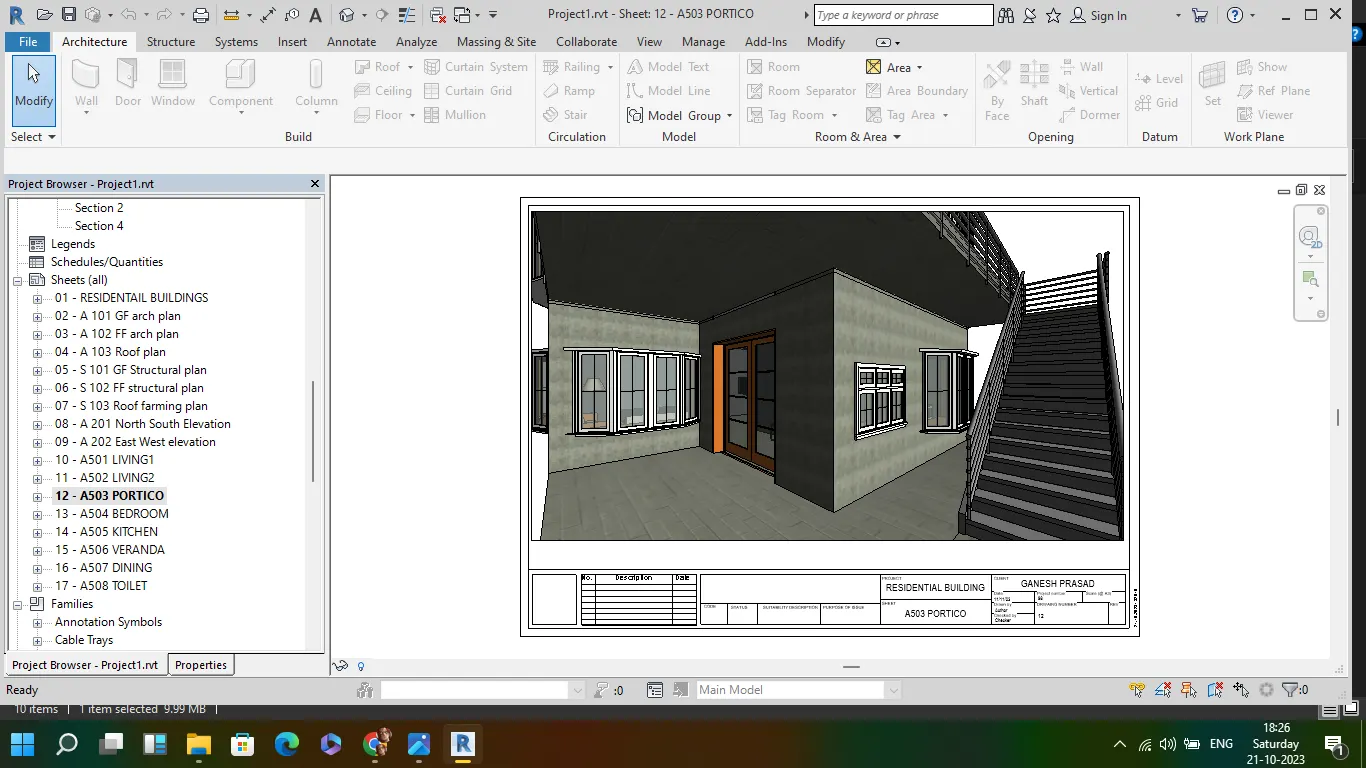
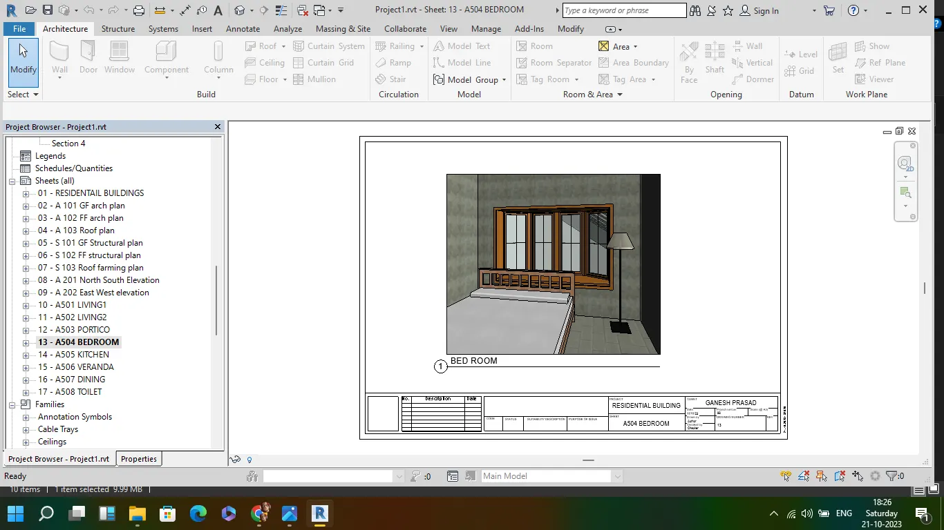
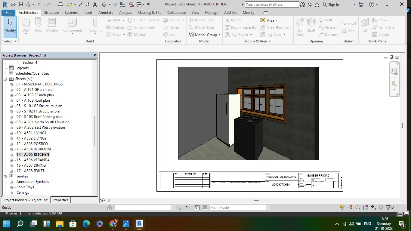
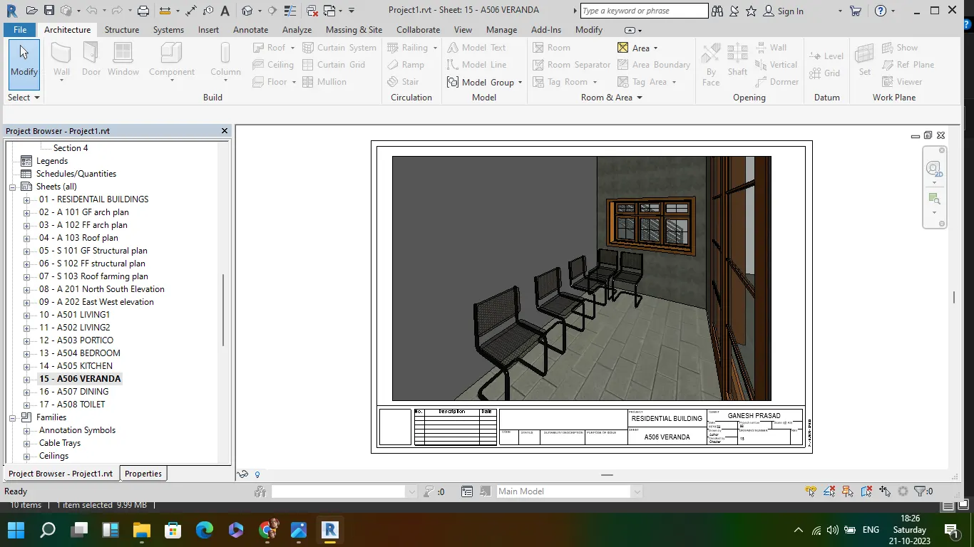
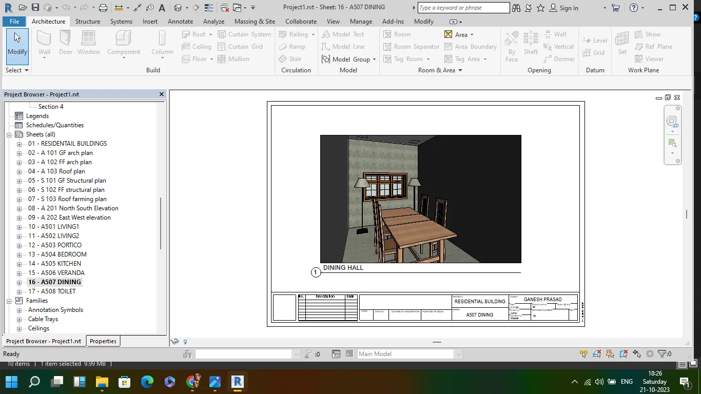
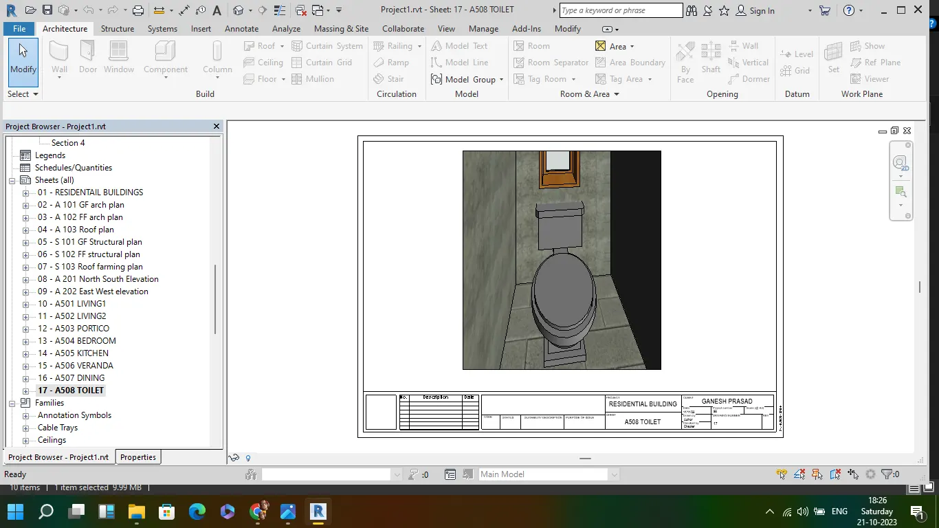
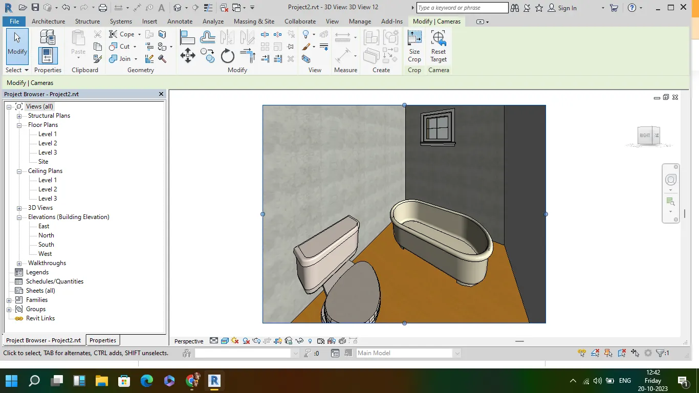
Aim: To create a camera-specific view or a 3D view in each room ( living, dining, bedroom). Based on the views create a new set of sheets starting A-501 (you can add as many sheets after, 502, 503.. n)to place the 3D view images. Produce the sheets as a part of project drafting.
- go to view in that 3D and select camera
- place the camera in the required position of each rooms of the building and capture the views of each
- this views are created uder 3D views in project browser and rename each views to respected rooms
- and in view tab create new sheets and rename it as A 501 to required numbers
- drag each 3D camera views in to sheet to form a template