2-D Meshing of an Automobile Dashboard using ANSA
Aim:
1) To check the geometric errors and rectify them for the given CAD Model.
2) To take the Mid Surface and Mesh the component according to the given quality criteria below.
| S.No | Quality Criteria | Value |
| 1 | Target/Average length | 4 |
| 2 | Minimum Length | 2 |
| 3 | Maximum Length | 6 |
| 4 | Aspect | 3 |
| 5 | Warpage | 15 |
| 6 | Skewness | 45 |
| 7 | Jacobian | 0.7 |
| 8 | Minimum Quad Angle | 45 |
| 9 | Maximum Quad Angle | 135 |
| 10 | Minimum Tria Angle | 30 |
| 11 | Maximum Tria Angle | 120 |
| 12 | Tria Percentage | 15 |
3) To Assign thickness to the component after meshing it.
Theory:
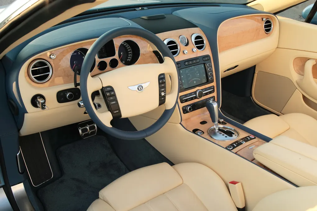
The CAD Model given to us is a Dashboard Sub Part. It is a plastic component where the Instrument Panel, HVAC vents and Infotainment Systems get attached. There are even other controls which get attached to the dashboard.
Procedure:
1. Importing the Model:
1) We first import the CAD model to the ANSA database using the Open option in the File tab.
2) After that, we set the perimeters and macros of the CAD model to 1 mm for better visualization of all the areas using the Length option present under Perimeters tab of the Mesh module as shown in the images given below.
3) After that, we perform topology over the whole CAD model so that the surface get properly stitched to each other using the TOPO option present under the Faces tab of the TOPO module as shown in the image given below.
2. Geometry Cleanup:
1) In this process, we clean up all the errors present in the CAD geometry like unchecked faces, needle faces, triple cons, single cons, cracked faces etc.
2) We go to the check geometry option present in tools tab to check for geometrical errors in the CAD model as shown in the image given below.
3) We then, get the clear all errors one by one manually to get a good geometry of the CAD model and again run the geometry check, therefore we get a check CAD geometry with no errors on it as shown in the images given below.
4) We store a locked view of the parent geometry before taking the mid surface using the Lock option present in the Focus tab.
3. Mid Surfacing:
1) We have to measure the whole geometry region by region so that we can create a mid surface without any confusion.
2) We use the Measure option present under the Utilities tab to the measure the whole component region by region as shown in the image given below.
3) After that, according to the measurements taken from the parent geometry we start taking the mid surface for component region by region.
4) We use different options to take the mid surface in different regions like the Offset, Middle, Mid surface-skin (Auto mid) etc present in the Faces tab.
5) For the attaching clip-ons(pillar like surfaces) we create curves using the create option under the curves tab of the TOPO module on the middle of the pillar or cylindrical surfaces so that we can create mid surface.
6) We finally obtain the mid surface from the parent geometry as shown in the image given below.
7) We again store a locked view of the mid surface using the Lock option present in the Focus tab.
8) We set seperate Part ID's and Material ID's for the mid surfaced components as shown in the images given below.
4. Meshing and Assigning Thickness:
1) We first, setup the mesh parameters like min length, max length and target element length using mesh parameters option under the utilities tab as shown in the image given below.
2) After that we setup the quality criteria according to the given values in the aim of using quality criteria option under the utilities tab as shown in the image given below.
3) In the 2-D meshing we will be considering only the above mid surfaced parts and we will be meshing it with mixed elements that include both quad and tria elements according the quality criteria given in the aim. There are some important quality parameters required for the meshing the component namely:
1) Warp angle:
It is defined as the angle between the normal of the two planes by splitting the quad element along the diagonal. So, the maximum angle allowed between the two possiblities is called the warp angle. Warp is not applicable in the triangular element. The ideal value is 0 degree but less than 10 degree is acceptable for good practices.
2) Aspect Ratio:
It is defined as the ratio of max element edge length to the minimum element edge length. the ideal value is 1 but less than 5 is acceptable.
3) Skewness:
If the quad element is not square and has deformation then the skewness defined for as the 90 minus the minimum angle between the two lines joining the opposite mid sides of the element and similarly for the triangular element it is 90 minus the between the line from each node to the opposing mid-side. The ideal value is 0 but less than 45 degree is acceptable.
4) Jacobian:
It is the scale factor used in the transformation of the co-ordinated system.(global to a local coordinate system). This is used for a faster analysis point of view. The ideal value is 1 but greater than 0.6 is acceptable.
5)Minimum element length:
It is very important to check for crash analysis(time step calculation). it is also done to avoid the presence of any zero length element.
6) Target element length:
It is the size of the element by which we can get the most nearer approximate value of the result compared to the experimental result.
4) We start 2D meshing of the component region by region so we can obtain a better mesh flow as shown in the image given below.
5) We clear all the quality issues in the mesh to get a good error free mesh over mid surface of the component.
6) We finally get to see the completly meshed model as shown in the image given below.
7) We then assign thickness to the meshed component by ticking the checkbox called 'Draw shell as solid' present in presentation parameters of quality criteria under the utilities tab as shown in the image given below.
8) We finally get the meshed model which is same as the parent geometry as their respective PID's have the original thickness of the parent geometry as shown in the image given below.
Conclusion:
1) We have check the given CAD geometry for the geometrical errors and rectified them using checks geometry option.
2) We have generated mid surface from the parent gemetry region by region so as to get a perfect Mid Surface.
3) We have performed 2-D meshing over the mid surfaced geometry region by region and clearing all the qualty errors to get a better mesh flow over the component.
4) Finally, we have assigned thickness to the model which matches the parent geometry thickness.
Learning Outcomes:
1) Taking mid surface for complex geometry like dashboard.
2) Obtaining better mesh flow over the dashboard.
Model Link:
https://drive.google.com/drive/folders/1TuoDOfGi2CHa19FcAlgkojciUZZinhu1?usp=sharing