What is Phase-Locked Loop?
A phase-locked loop (also a phase lock loop or PLL) is a system that generates an output signal whose phase is related to its input. The two signals will have the same frequency and either no phase difference or a constant phase difference between them.
 Skill-Lync·15 Jun 2023·3 min read

What is a Phase-Locked Loop?
A phase-locked loop (also a phase lock loop or PLL) is a system that generates an output signal whose phase is related to its input. The two signals will have the same frequency and either no phase difference or a constant phase difference between them.
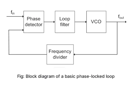
A PLL typically consists of a phase detector, a loop filter, and a voltage-controlled oscillator (VCO). The phase detector compares the reference signal with the oscillator frequency and outputs an error signal. The loop filter (usually a low-pass filter) then generates an error voltage from the error signal. The VCO then increases or decreases the oscillator frequency to lock to the input frequency. This produces an output frequency that is equal to the input frequency and a constant phase shift (which could be zero) between the two signals. A PLL may also have a frequency divider in its feedback loop in order to create an output that is a multiple of the reference frequency instead of one that is exactly equal to it.
Operation
The PLL locks the frequency of a voltage-controlled oscillator to a reference signal injected on input. The heart of the PLL is the VCO that provides on the output a sinusoidal or square signal whose instantaneous frequency fs(t) depends on the control voltage Vf.
The phase comparator develops a voltage vr(t) that is related to the phase shift between input and output signals, “ve” and “vs.” respectively. The low-pass filter eliminates higher frequencies and gives to its output the average value of the voltage VR (t) or its slowly varying component by removing all of the high-frequency harmonics.
In the absence of a signal applied on input, the VCO operates at its own oscillation frequency, F0. When a signal of frequency fe is applied on input, the loop enters a transient state, where VR(t) and Vf vary in a complex fashion. This transient state is called locking or capture. At the end of the transient state, the loop is locked, and the frequency of the voltage-controlled oscillator (VCO) is equal to that of the input signal. The frequency of the signal at the VCO output will depend on the value of the control voltage Vf.
The PLL locking range mainly depends on the characteristics of the voltage-controlled oscillator. This range goes from frequency Fmax to frequency Fmin. The capture range, which is much less extensive than the locking range, mainly depends on the characteristics of the low-pass filter.
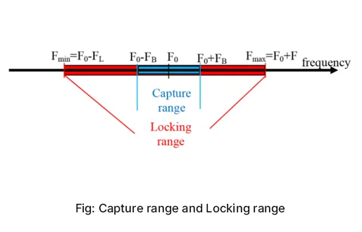
The capture range bandwidth is equal to 2FB, and the bandwidth of the locking range is equal to 2FL. It should be noted that FB < FL. Fmax and Fmin are, respectively the maximal and minimal frequencies that the voltage-controlled oscillator is able to cover.FB is based on the bandwidth of the loop filter i.e. the range of frequency which the filter can accept. FL is the locking range frequency
What are the three stages through which a PLL operates?
The three stages of a phase-locked loop are free running, capture, and phase lock or tracking:
- Free running- the center frequency of the PLL, which is the frequency that the VCO runs at when not locked to the input frequency.
- Capture- in order for the VCO to lock to the input frequency initially, the frequency must be within the PLL’s capture range.
- Phase lock (or tracking)- once the VCO has locked to the input frequency, it will continue to track and adjust to the input frequency as long as it stays within the PLL’s lock range. The lock range is wider than the capture range.
Application
- Phase-locked loops are used extensively within the telecommunications industry for frequency multiplication, data extraction, and re-timing purposes.
- FM demodulation networks for FM operations
- It is used in motor speed controls and tracking filters.
- It is used in frequency-shifting decodes for demodulation carrier frequencies.
- It is used in time for digital converters.
- It is used for Jitter reduction, skew suppression, and clock recovery.