How Does a Battery Management System (BMS) Work? A Guide for EV Engineers
A battery management system measures every cell, estimates state of charge, health and power, balances cells, protects the pack and talks to the rest of the vehicle. Here is how each function works, with worked numbers.
 Skill-Lync·Updated 17 Oct 2026·10 min read
In short
- A battery management system (BMS) is the electronics and software that keep every cell in a battery pack inside its safe voltage, current and temperature window.
- It does six jobs: measure, estimate (state of charge, health and power), balance, protect, coordinate thermal management, and communicate with the rest of the vehicle.
- The BMS does not charge the battery or cool it by itself. It tells the charger, inverter and cooling system what the pack can safely accept.
- In India, EV battery packs must meet AIS-156 (two- and three-wheelers) or AIS-038 Rev. 2 (cars, buses and trucks), both of which put requirements on the BMS.
What is a battery management system?
A lithium-ion cell is efficient and energy-dense, but unforgiving. Charge it a little too high, discharge it too low, push too much current, or let it get too hot or too cold, and it ages fast or, in the worst case, goes into thermal runaway. A phone has one cell and a simple protection chip. An electric vehicle has hundreds or thousands of cells working together, and that is where a BMS comes in.
A BMS is the combination of sensing hardware, a controller and software that watches every cell group, works out how much energy and power the pack can deliver right now, and acts when something goes outside limits. Think of it as the pack's brain and its safety officer at the same time.
Why a pack needs one: a quick example
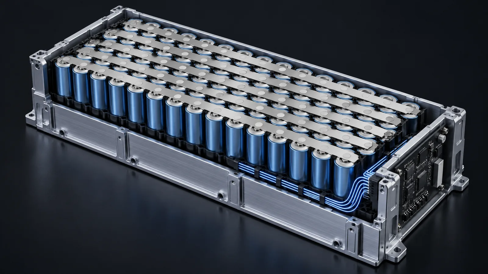
Cells are connected in series to build voltage and in parallel to build capacity. A pack described as 96S2P has 96 groups in series, each group made of 2 cells in parallel. With cells of 3.65 V nominal and 60 Ah:
- Pack voltage: 96 × 3.65 V ≈ 350 V nominal
- Pack capacity: 2 × 60 Ah = 120 Ah
- Pack energy: 350 V × 120 Ah ≈ 42 kWh
In series, the same current flows through all 96 groups, but the groups are never perfectly identical. One group with slightly lower capacity reaches its upper voltage limit first when charging and its lower limit first when discharging. Without a BMS watching each group, that weakest group would be over-charged or over-discharged on every cycle. The pack is only as good as its weakest cell, and the BMS is what protects that cell.
BMS architecture
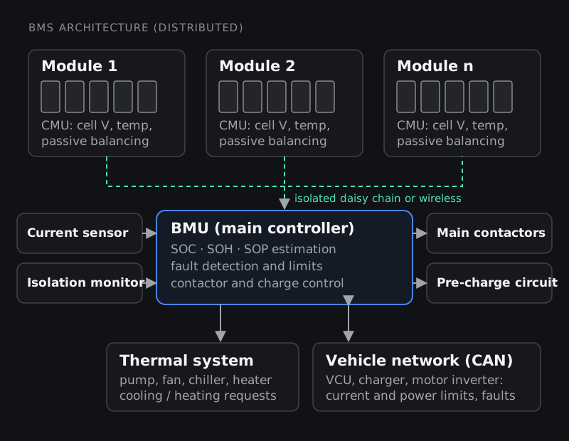
Most EV packs use a distributed (or modular) architecture. Each module carries a cell monitoring unit (CMU), built around an analogue front-end IC that measures every cell voltage and a few temperatures and switches the balancing circuits. The CMUs report to a battery management unit (BMU), the main controller, over an isolated daisy-chain link. The BMU also reads the pack current sensor and the isolation monitor, runs the estimation algorithms and drives the contactors.
| Architecture | How it is built | Where it fits |
|---|---|---|
| Centralised | One board, wires from every cell to it | Small packs: e-bikes, scooters, power tools, small storage |
| Distributed / modular | One monitoring board per module plus a main controller | Most EV and large stationary packs; easier to scale and service |
| Wireless | Module monitors talk to the controller by radio instead of a wired daisy chain | Reduces harness weight and assembly work; Analog Devices announced the first production wireless BMS for GM's Ultium battery platform in 2020 |
Function 1: measurement
Everything a BMS does depends on what it measures, and how well:
- Cell voltages: every series group, typically every few milliseconds. Accuracy matters more than you might expect, especially for LFP cells, whose voltage curve is so flat in the middle that a few millivolts can represent a large change in state of charge.
- Pack current: through a shunt resistor or a Hall-effect sensor. This is the input to coulomb counting, so offset and gain errors directly become state-of-charge errors.
- Temperatures: NTC thermistors on cells, busbars and coolant lines. Not every cell has its own sensor, so placement is a design decision in itself.
- Isolation resistance: between the high-voltage system and the vehicle chassis, so a fault that could make the body live is detected.
Function 2: state estimation (SOC, SOH, SOP)
None of the numbers a driver cares about can be measured directly. The BMS estimates them from voltage, current, temperature and a model of the cell.
State of charge (SOC)
SOC is the remaining charge as a percentage of the cell's present capacity: the fuel gauge. The basic method is coulomb counting, integrating current over time.
Worked example. The 120 Ah pack above starts at 80% SOC and supplies a steady 40 A for 30 minutes. Charge removed = 40 A × 0.5 h = 20 Ah. New SOC = 80% − (20 / 120) × 100% ≈ 63.3%.
The weakness is drift. If the current sensor reads just 0.2 A high, over 10 hours that is 2 Ah of error, or about 1.7% of SOC, and it keeps growing. So real BMS software corrects coulomb counting with other information: the open-circuit voltage after the pack has rested, and model-based estimators such as Kalman filters that compare measured voltage with what an equivalent-circuit cell model predicts. If you want to see what that model looks like, our technical post on modelling a Li-ion battery equivalent circuit walks through one.
State of health (SOH)
Cells lose capacity and gain internal resistance as they age. SOH tracks this, usually as present capacity divided by rated capacity, and sometimes as resistance growth. It feeds warranty decisions, range prediction and second-life use. Many automotive warranties treat a pack as worn out when its capacity drops to roughly 70 to 80% of new.
State of power (SOP)
SOP answers "how much current or power can I take or put back for the next few seconds without breaking a limit?" It depends on SOC, temperature and resistance. A cold pack at low SOC might allow only a fraction of its normal regenerative braking or acceleration power. The BMS sends these limits to the motor inverter and charger continuously.
Function 3: cell balancing
Balancing brings cell groups back to the same SOC so the whole pack's capacity is usable. There are two families:
- Passive balancing bleeds charge from the highest cells through a resistor, turning the excess into heat. Simple, cheap and by far the most common.
- Active balancing moves charge from high cells to low cells using capacitors, inductors or transformers. More efficient and faster, but more complex and expensive.
Worked example. A passive balancing channel uses a 33 Ω resistor across a cell at 4.0 V. Bleed current = 4.0 / 33 ≈ 121 mA, dissipating about 0.48 W. If one 120 Ah parallel group is 1% higher in SOC than the rest, that is 1.2 Ah of excess charge, which takes 1.2 / 0.121 ≈ 10 hours to bleed off. That is why passive balancing runs whenever it can, including during charging and while the vehicle is parked, and why it is designed to correct small, slow drifts rather than large mismatches.
Function 4: protection
Protection is the BMS's most safety-critical job. It compares measurements with limits and, when one is crossed, first reduces the allowed current and, if needed, opens the main contactors.
| Fault | Why it matters | Typical response |
|---|---|---|
| Over-voltage | Overcharging stresses the cathode and electrolyte and can trigger thermal runaway | Stop charging, open contactors if it persists |
| Under-voltage | Deep discharge can dissolve the copper current collector and damage the cell permanently | Reduce power, then disconnect the load |
| Over-current / short circuit | Rapid heating, damage to busbars and fuses | Limit current; a pyro-fuse or fuse handles hard shorts |
| Over-temperature | Faster ageing; risk of runaway | Request cooling, derate power, disconnect at hard limits |
| Under-temperature (charging) | Charging lithium-ion cells below about 0 °C can plate lithium metal on the anode | Block or limit charging, request heating |
| Isolation fault | Shock risk from the high-voltage system | Warn, and prevent HV activation |
Voltage limits depend on cell chemistry: an NMC cell is typically charged to about 4.2 V and an LFP cell to about 3.65 V, with lower cut-offs around 2.5 to 3.0 V. Always take the actual numbers from the cell datasheet, never from a generic table.
Contactors and pre-charge
The BMS also controls how the pack connects to the vehicle. The motor inverter has a large DC-link capacitor at its input. Closing the main contactor straight onto an empty capacitor would cause a huge inrush current that can weld contactor tips. So the BMS first closes a pre-charge contactor in series with a resistor, waits until the inverter voltage reaches most of the pack voltage, and only then closes the main contactor. If the voltage does not rise as expected, that is itself a fault signal.
Function 5: thermal management
Lithium-ion cells live longest in a moderate temperature band and need to stay close to each other in temperature. The BMS measures temperatures and decides what the pack needs, but the cooling and heating hardware is a separate battery thermal management system: air cooling for small packs, liquid-cooled cold plates for most cars, and electric heaters or heat pumps for cold climates. The BMS requests more coolant flow, a fan speed or heating, and reduces the allowed charge or discharge power when the pack is too hot or too cold. For more on the hardware side, read our post on battery thermal management systems in EVs.
Function 6: communication and data logging
The BMS talks to the vehicle control unit, the motor inverter and the charger, usually over CAN. It sends SOC, available power limits, faults and charging requests; during charging it tells the charger what current and voltage the pack can accept at every moment. It also logs data for diagnostics and warranty. Indian EV battery safety standards, AIS-156 for L-category vehicles (two- and three-wheelers) and AIS-038 Rev. 2 for M and N category vehicles (cars, buses and goods vehicles), were amended after a series of EV fires in 2022 and include requirements such as thermal propagation testing and BMS data logging. If you work on Indian vehicles, read the current text of the standard that applies to yours.
Inside a BMS: hardware and software
- Hardware: cell-monitoring analogue front-end ICs, an automotive microcontroller (often with lockstep cores for safety), an isolated communication link, current sensing, contactor drivers and a power supply that keeps working at low pack voltages.
- Software: measurement drivers, estimation algorithms, protection state machines, balancing logic, diagnostics and communication stacks. Much of the algorithm work is done with model-based design in MATLAB and Simulink and then generated into embedded C, often within an AUTOSAR software architecture.
- Safety process: because BMS failures can cause fires, automotive BMS development follows the functional safety standard ISO 26262, with hazard analysis, safety goals and the verification that goes with them.
- Testing: hardware-in-the-loop (HIL) rigs simulate cells and faults so the BMS can be tested safely, before it ever connects to a real pack.
What does a BMS engineer work on?
BMS teams combine electrical, embedded and battery engineers. Typical work includes cell characterisation and modelling, SOC and SOH algorithm development, protection and diagnostic logic, hardware design for the monitoring boards, embedded software, and validation on HIL rigs and real packs. The skills that keep coming up in job descriptions are battery fundamentals, MATLAB and Simulink, embedded C, CAN, and a working knowledge of functional safety.
Ways to build those skills at Skill-Lync:
- Introduction to Battery Technology for Electric Vehicles: cells, packs, modelling and BMS basics in MATLAB and Simulink.
- Li-ion Battery System Design in EV and ES: pack design and sizing.
- Battery Thermal Management using Ansys Fluent and MATLAB: the thermal side.
- Post Graduate Program in Electric Vehicle Design and Development: the full EV system, including BMS projects.
Frequently asked questions
Does a BMS charge the battery?
No. The charger supplies the energy. The BMS tells the charger how much current and voltage the pack can accept, monitors every cell during charging, and stops the charge if a limit is reached.
What happens when a BMS fails?
A well-designed BMS fails safe: it opens the contactors and the vehicle loses drive power rather than running an unmonitored pack. Faults in sensing are the dangerous ones, because a BMS that reads the wrong voltage or temperature can allow abuse without knowing it. That is why measurements are cross-checked and diagnosed continuously.
Can a BMS damage battery life?
Poor calibration can. If SOC estimation drifts, or balancing is too weak, cells may spend time at higher voltages or deeper discharge than intended. A good BMS extends battery life by keeping every cell inside a conservative window.
Do LFP batteries need a BMS?
Yes. LFP is more thermally stable than NMC, but it still needs over-voltage, under-voltage, current and temperature protection, and its flat voltage curve makes SOC estimation harder, not easier.
What is the difference between a BMS and a BTMS?
The BMS monitors and controls the battery electrically. The battery thermal management system (BTMS) is the cooling and heating hardware. The BMS decides what the BTMS should do.
How do engineers check that a BMS is working?
On the bench and HIL rigs, they inject known cell voltages, currents, temperatures and faults and confirm the BMS measures and reacts correctly. In the field, they compare BMS-reported SOC and cell voltages with independent measurements and review the fault and event logs.
Sources and further reading
- Analog Devices, Analog Devices introduces automotive industry's first wireless battery management system (9 September 2020)
- ISO, ISO 26262-1:2018 Road vehicles: Functional safety
- MathWorks, What is a battery management system? (BMS functions and model-based design)
- Ministry of Road Transport and Highways, AIS-156 and AIS-038 (Rev. 2) battery safety standards and amendments