Wiring harness routing & packaging Rules Week 3 Challenge
AIM
To electrically define the given p clamp using catia software.
To electrically define the backshell given using catia software.
To create different COT tube as per given dimension as store under a catalogue.
PROCEDURE
In the case of p clamp
Download the cad file from the given link
Create point and plane in part design work bench
Define the cad electrically under electrical part design work bench
in the case of backshell
Download the cad file from the given link
Create point and axis in part design work bench
Define the cad electrically under electrical part design work bench
for the case of COT tube - cretion of COT tube is done under electrical part design work bench
THEORY
In the case of p clamp;point and plain is created first under part design work bench
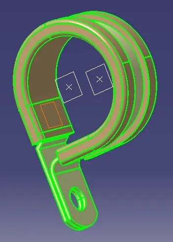
Centre of the circular curve on either circular surface is made.then a plane parallel to the circular surface passing through each points are made as shown in figure.in the base region a plain offset to the plane square surface is made.but the offset lenght is 0.
Then we go to electrical part design work bench to define them electrically.
Here we select this option
To define them,when we click first this dialog box opens.
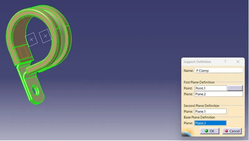
Here we gave the first plane as the first entry of bundle.Then point on that plane is given in point option.Then we give exit plane of the bundle in second plane.Then the 0 offst plane on the base is given as base plane.Here we have to do the same becausethe bundle can come in both plane direction. So we select the same option and give the exit plane of previous as first palne and it's point in point tab.Here second plane will be selected as entry plane in first as default.So we don't have to select them.Then select the base plane as selected in previous procedure.
In the case of backshell; point and axis is made in part design work bench.
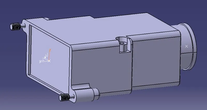
The rectangular face would be connecting the connector and the circular face would allow the wire to reach the connector through rectangular face.point on the centre of both face is created.in the rectangular face; axis coordinates are given where y axis is in the direction of mating and z&x axis facing sides of the backshell.
Then we define it electrically in electrical part design work bench by selecting this option
Later we gave additional details.next we select this option
To give details for connector attaching region.the details would be representation,orientaion etc.then we select this option
To give details for bundle attachment region.after giving respective details;the cad will be electrically defined.
In the case of creating COT tubes;everything would be done in electrical part design work bench.For that we have to select this option
Here we have to give details like inner diameter and thickness as to be said.the output would be seen as rib in part body.After creating all COT tube as per said;then we have to save and store them in a catalogue to use them in future.First we have to create catalogue by clicking new file and select catalogue and gave respective name and save them.Then these created COT tube files are saved and stored using this option
This catalogue would help in electrical assembling workbench for assembling.
RESULT
the given cad file( p clamp and backshell) is electrically defined and COT tube of various dimensions as asked has created and stored in a catalogue.