Wiring harness routing & packaging Rules Week 3 Challenge
Wiring harness routing & packaging Rules Week 3 Challenge
Aim: To download following cad data & define it as Electrical support using Electrical Part design Workbench. Define all the necessary properties.
Introduction:
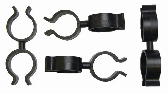
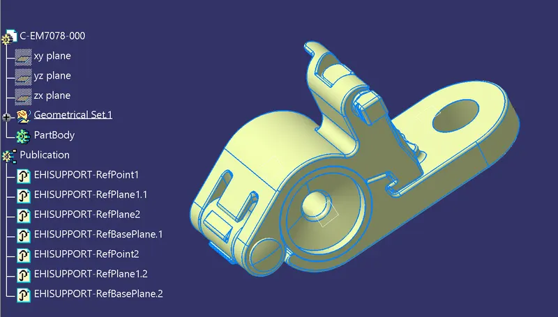
Clips: This is the important component of the wiring harness which would be defined before wiring harness routing. Clips accumulate the bundle in the amended position. The main points and planes in the clip are:
1) Entry point and plane
2) Base plane
3) Exit plane
There will be two entry and two exits for the clip, so the wire can accommodate in any of the directions.
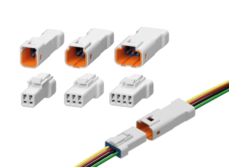
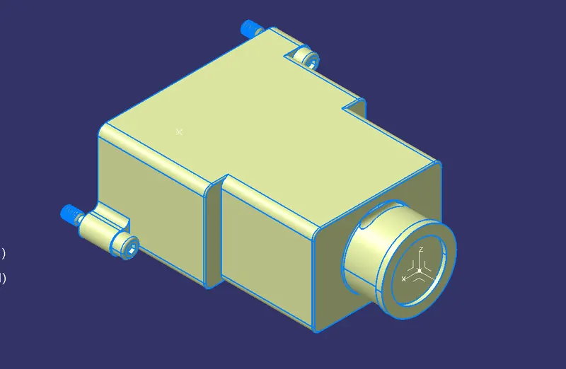
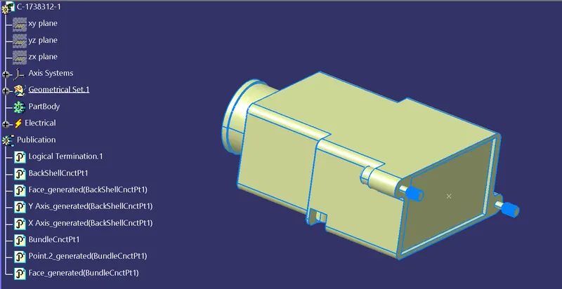
Backshell: These are the extra protecting parts for the bundle and connectors. These are not exactly required. There will be only one entry and one exit point.
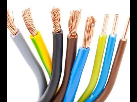
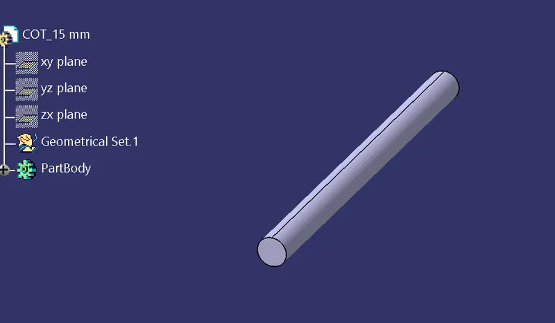
Corrugated Tubes & Insulation Tapes: These are protective covering for bundles. The color of the COT tubes defines the electrical component as specified by the customer.
Assign of Electrical properties:
CLIP:
1) Download the required part file from the te.com
2) In the part design create points and planes at the entry, exit and base.
3) Switch to Electrical part design, Select the DEFINE SUPPORT PART
4) Give the entry point and plane as first plane, exit as second plane and base as third plane.
5) Repeat the step 3 and 4, this time give opposite end as entry.
6) Clip electrical properties are assigned.
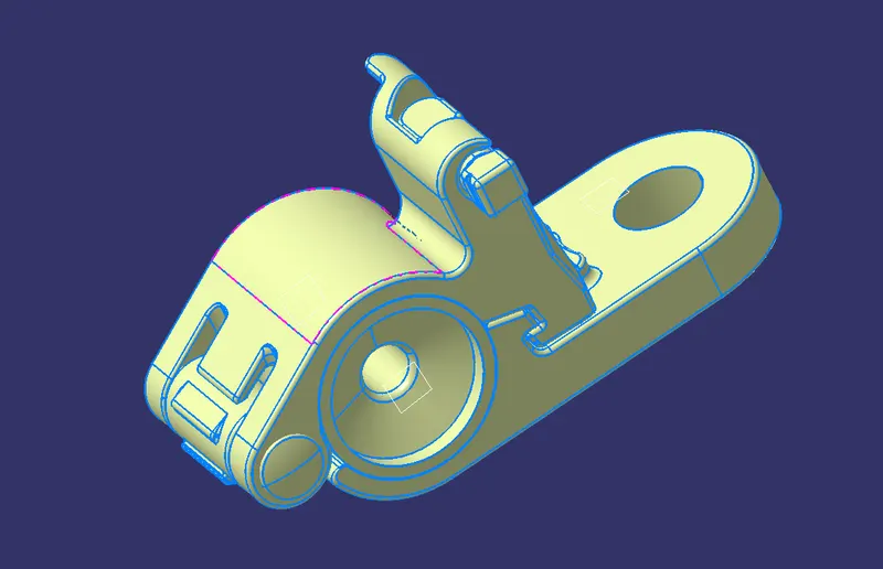
P clamp is not showing like as from reference video from te.com website, so i took another type clamp for defining properties.
BACK SHELL:
1) Download the back shell from te.com
2) Create point and axis at the bundle entry point (where connector comes into contact).
Y-axis: In the direction of bundle
X and Z – any direction.
3) Switch to Electrical part design. Click on DEFINE BACKSHELL. Select the part body, keep the type as uncut.
4) Now click on DEFINE BACKSHELL CONNECTION POINT. Give the representation as centre point, Coincidence as Y-axis and Orientation as X/Z axis.
5) Electrical properties to back shell are assigned.
CORRUGATED TUBES & INSULATION TAPES:
1) Create a new part in electrical part design.
2) Select DEFINE PROTECTION PART
3) select the axis system.
4) Give the inner diameter, outer diameter and save the cot tube in separate catalogue created for corrugated tubes and insulation tapes.
5) Repeat the same steps for creating all corrugated tubes
6) Repeat the same procedure but this time select tapes in the protective part type and save the part in tapes catalogue.
7) Electrical properties are assigned to corrugated tubes and insulation tapes.
Creates Following Corrugated tubes & Added them in Catalogue under “Slit COT” family.
|
Name |
ID (mm) |
OD (mm) |
Thickness (mm) |
|
15mm COT |
12 |
15 |
1.5 |
|
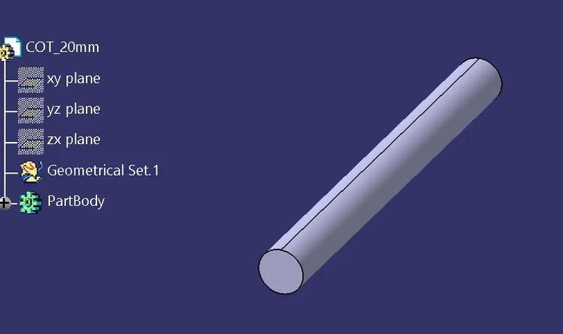
20mm COT |
17 |
20 |
1.5 |
|
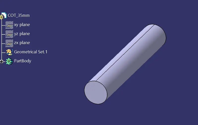
35mm COT |
32 |
35 |
1.5 |
|
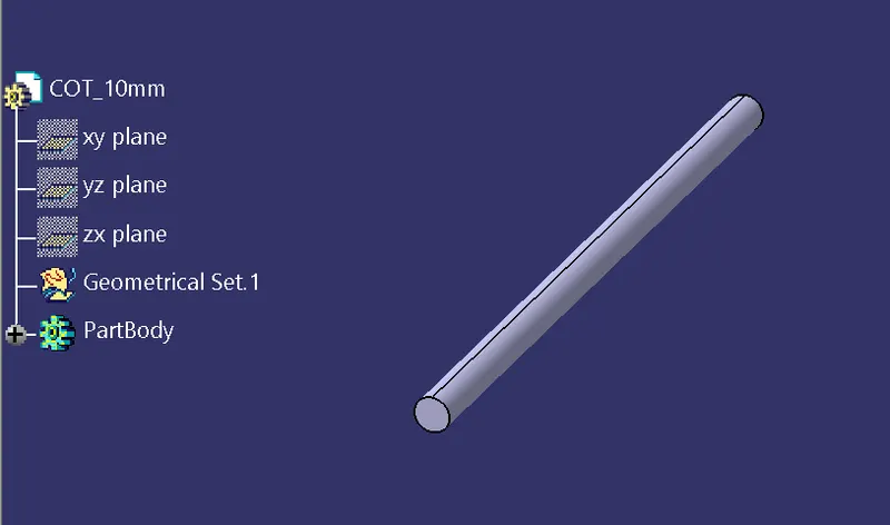
10mm COT |
7 |
10 |
1.5 |
|
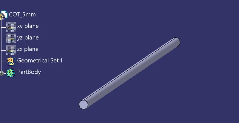
5mm COT |
3 |
5 |
1 |
15mm COT:
20mm COT:
35mm COT:
10mm COT:
5mm COT:
Conclusion:
Hence, downloaded following cad data from TE.com & defined them as Electrical support using Electrical Part design Workbench. Defined all the necessary properties.