Wiring harness routing & packaging Rules Week 3 Challenge
1. P-CLAMP
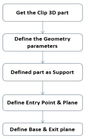
Fig. shows the flowchart to define the CLAMPS
- First create the geometrical parameters to the CAD model such that it contains entry point and exit poit with parallel planes and base plane.

- Define the clamp support in the Electrical part design workbench
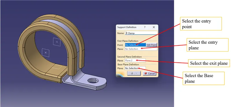
- Do the same for exit point
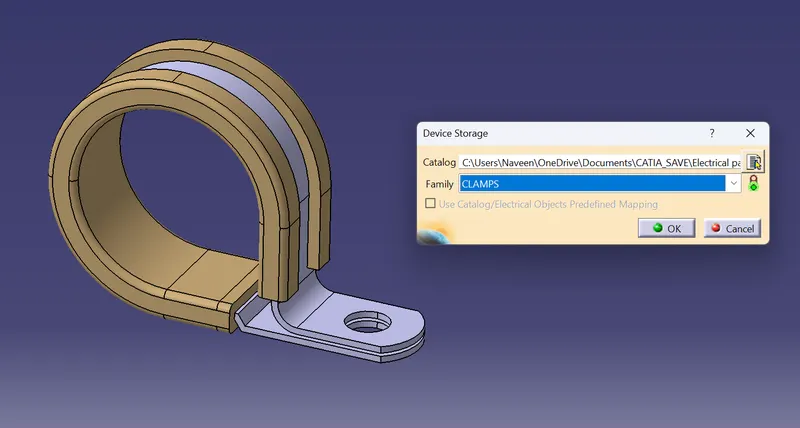
use the storage tool to save part in the catalogue
2. Back shell
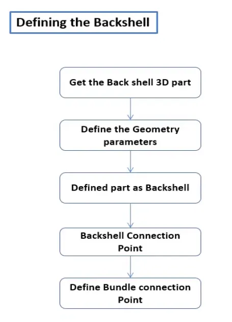
Fig. shows the flowchart for the creation of Electrical Backshell
- Geometrical definitions
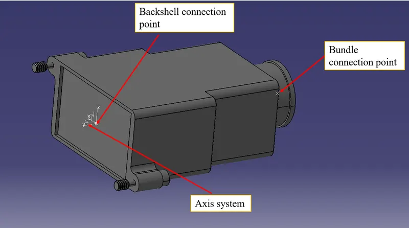
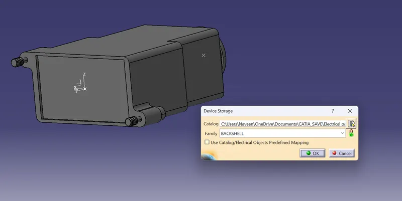
- Define the Backshell as Electrical backshell in the Electrical part design using Define Back shell tool and also give Back shell connection point and Bundle connection point in the same workbench
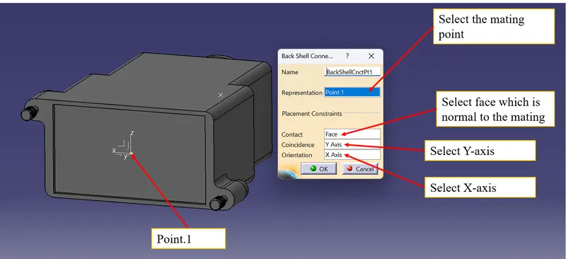
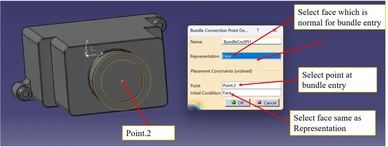
save the model in the catalog using storage tool in EPD workbench.
3. Corrugated tubes
|
Name |
ID (mm) |
OD (mm) |
Thickness (mm) |
Calculated Bend radius(1.5*OD) |
|
15mm COT |
12 |
15 |
1.5 |
22.5 |
|
20mm COT |
17 |
20 |
1.5 |
30 |
|
35mm COT |
32 |
35 |
1.5 |
35 |
|
10mm COT |
7 |
10 |
1.5 |
15 |
|
5mm COT |
3 |
5 |
1 |
7.5 |
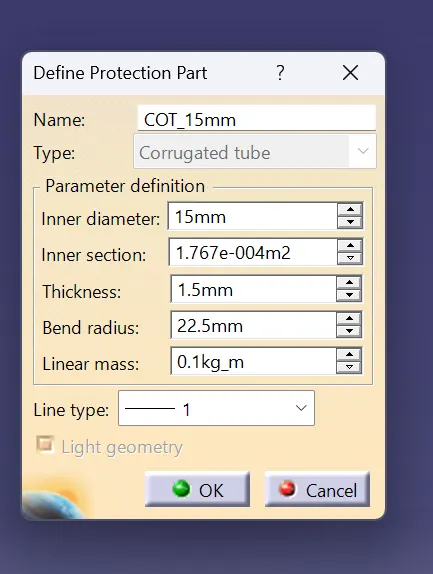
- The tube is created using Define protection part tool in the EPD and select the appropriate diemensions for the below window as mentioned in the above table.
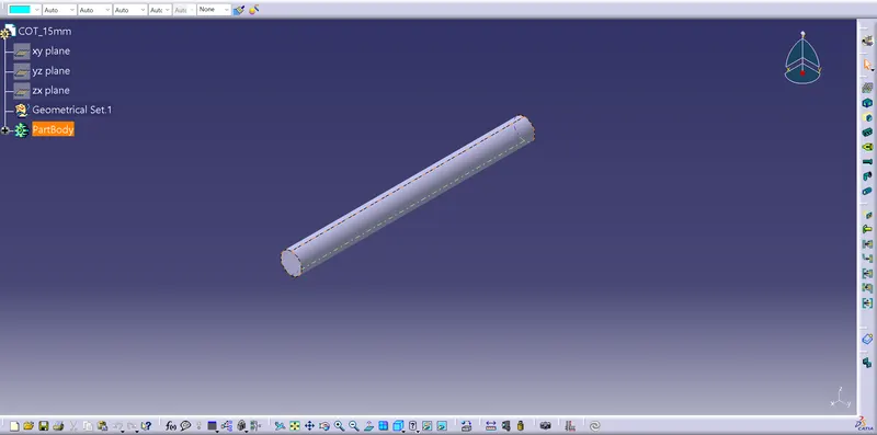
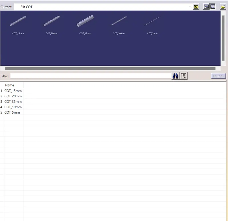
save the model in the catalog,name the family as "Slit COT" using storage tool in EPD workbench.
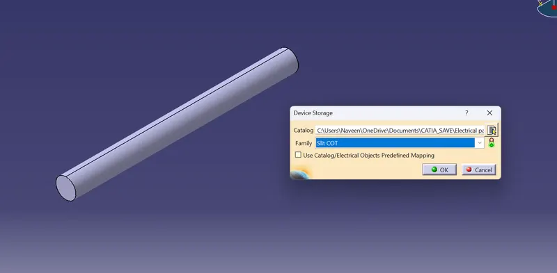
- Do the same for the rest of the dimensions