Wiring harness design in CATIA V5 - 3D modeling Week 7 Challenge
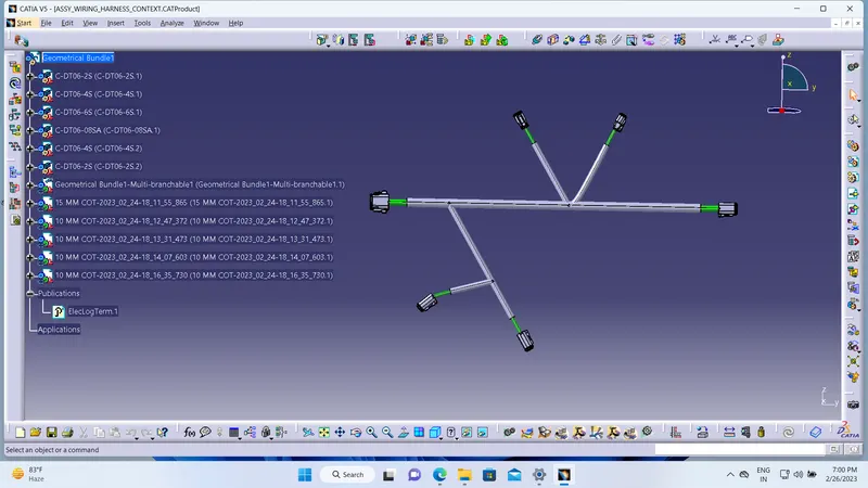
As per the image attached below wiring harness assembly is created according to the layout mentioned above with all the connectors are electrically defined and with corrugated tubes added to necessary bundles.
After that the CAT product file of harness assembly is exracted to flattening workbench where all the flattening properties are defined and once the CAT product is extracted the file now is saved as .EHF(Electrical Harness Flattening Assembly) file and now the flattening file is saved in the location where wiring harness assembly is saved. Now the harness assembly is flattened using Flatten command as per the image shown below.
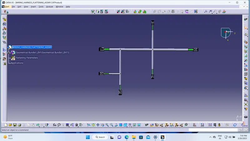
Once the flattened product is obtained make all the necessary changed like scaling, rolling, rotating, straightening etc. Now transfer the flattened assembly on to the 2D drawing sheet by creating new drawing sheet and save the drawing sheet in the same location as all the files saved before.
Now select the front view option and select the plane of the flattened which was selected earlier in the flattening properties.
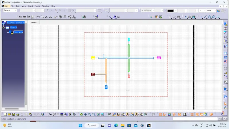
Now the 2D diagram of flattened model is displayed on the drawing sheet, now to go the that drawing properties and in the view section make sure 3D wire frame is always visible which represents the bundles and make sure the graphic for device is 3D projection for better identification and understanding and single line for bundle and double line for protective coverings, and 3D colors can be addes for better look as per the image shown below.