Wiring harness design in CATIA V5 - 3D modeling Week 7 Challenge
AIM:
To Flatten the harness assembly .And Place the flattened view on drawing sheet.To Ensure bundles with protective coverings has different visuals on drawing view.
OBJECTIVE:
- To flatten the wire harness assembly completed in week 4 assignment.
- To orient the wire bundle as shown in the layout.
- To place the flattened view on a drawing sheet.
- To ensure bundles with protective coverings has different visuals on drawing view.
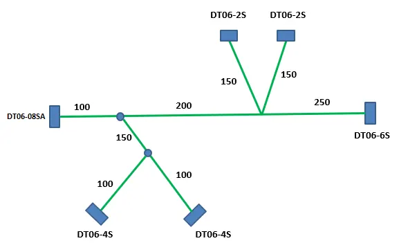
HARNESS FLATTENING:
- WE GO TO THE HARNESS FLATTENING WORKBENCH AND DEFINE THE HARENESS FLATTENING PARAMETERS. TO ENSURE THAT THIS OPTIONS ARE ALL GET SELECTED.
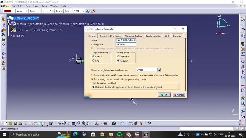
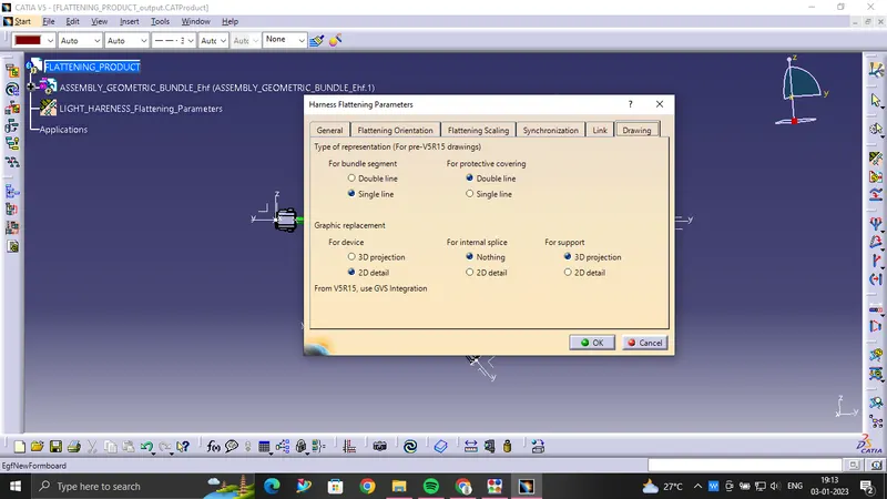
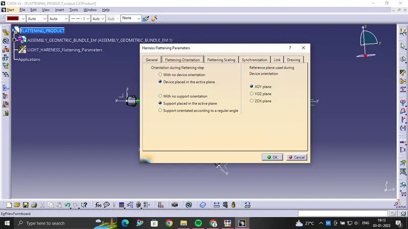
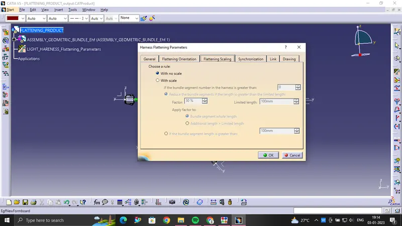
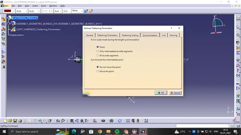
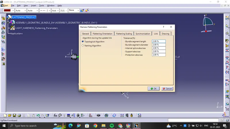
- WE USE THE EXTRACT COMMAND TO BRING THE HARNESS ASSEMBLY TO THE FLATTENING WORKBENCH HERE.
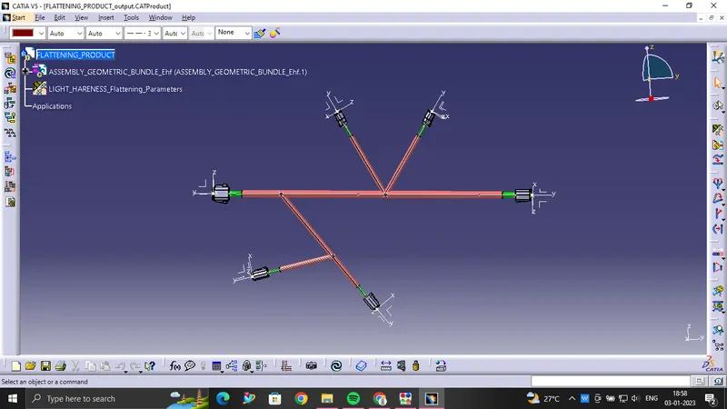
- CHOOSING A SUITABLE PLANE WE FLATTEN THE HARNESS ASSEMBLY.
- BUNDLE SEGMENTS ARE ROTATED AT THE REQUIRED ANGLES. THE HARNESS ASSEMBLY IS THEN DRAFTED.
- FLATTENING PARAMETERS ARE DEFINED IN ORDER TO MAKE THE BUNDLE AND THE CORRUGATED TUBES VISIBLE IN THE 3D DRAWINGS.
HARNESS ASSEMBLY:
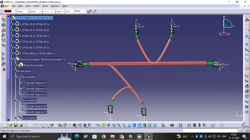
THIS ARE THE COMMANDS USED TO FLATTEN THE WIRE:

AFTER APPLIED THE HARNESS FLATTENING:
FOR DRAFTING:
- Create a new drawing file and save the file in the same location.
- Insert the title block template and fill up the required details.
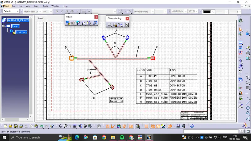
- Add the front view of the harness assembly by selecting any one of the flat faces of the connector and orient the view as per the requirement.
- Go to the properties of the view and select the 3D Wireframe on and Is always visible option in order to see properly the Wire bundle, connectors and the protection coverings.
- Show and name all the parts used in the wire harness assembly in form of a table.
CONCLUSION:
To Flatten the harness assembly .And Place the flattened view on drawing sheet.To Ensure bundles with protective coverings has different visuals on drawing view is successfully completed.