Wiring harness design in CATIA V5 - 3D modeling Week 7 Challenge
DT06-2S:

This connector housing consists of 2 terminals, it is defined as an electrical connector using electrical part design workbench. The axis system is created at the mating part of the connector, where the X,Y,Z axis are placed at the direction of the locking mechanism of the chip, mating front face of the connector and in the point across the connector from left to right respectively. Then the Connector connection point ,Bundle connnection point and catalogues for the connector also created.
DT06-4S:
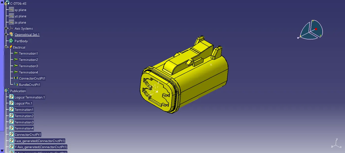
This connector housing consists of 4 terminals, it is defined as an electrical connector using electrical part design workbench. The axis system is created at the mating part of the connector, where the X,Y,Z axis are placed at the direction of the locking mechanism of the chip, mating front face of the connector and in the point across the connector from left to right respectively. Then the Connector connection point ,Bundle connnection point and catalogues for the connector also created.
DT06-6S:
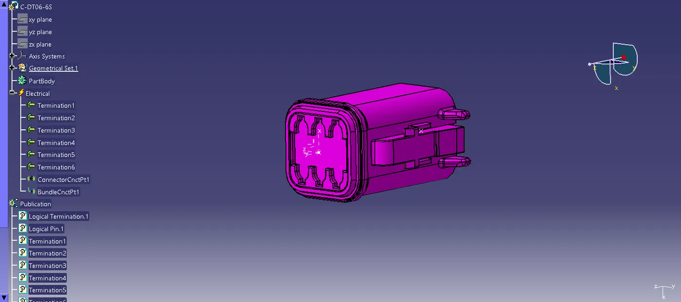
This connector housing consists of 6 terminals, it is defined as an electrical connector using electrical part design workbench. The axis system is created at the mating part of the connector, where the X,Y,Z axis are placed at the direction of the locking mechanism of the chip, mating front face of the connector and in the point across the connector from left to right respectively. Then the Connector connection point ,Bundle connnection point and catalogues for the connector also created.
DT06-08SA:
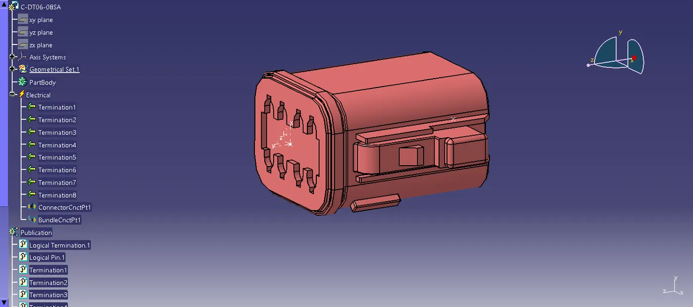
This connector housing consists of 8 terminals, it is defined as an electrical connector using electrical part design workbench. The axis system is created at the mating part of the connector, where the X,Y,Z axis are placed at the direction of the locking mechanism of the chip, mating front face of the connector and in the point across the connector from left to right respectively. Then the Connector connection point ,Bundle connnection point and catalogues for the connector also created.
Bundle routing:
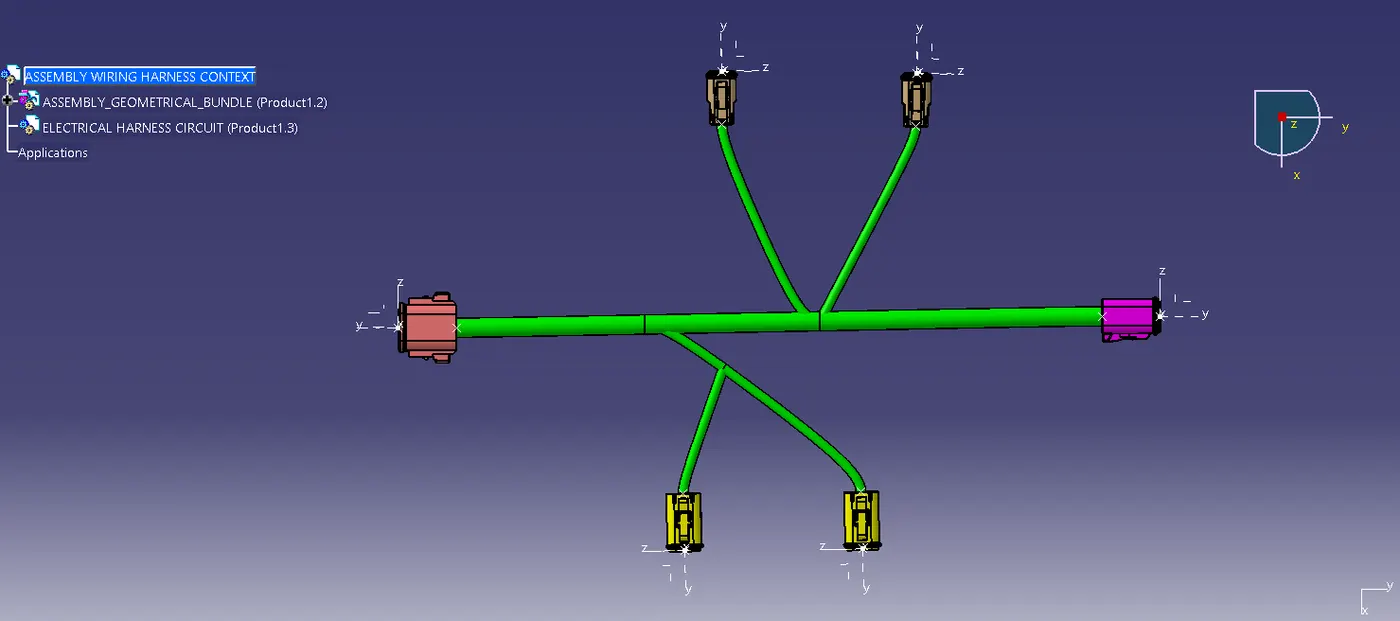
Based on the given layout, the electrically defined connectors are assembled. Creating the wiring harness geometrical bundle, inserted harness components into geometrical bundle. Positioned the electrical parts by manipulation, translation and rotation. Then defined the wiring harness routing.
In Electrical harness assembly workbench, created the multi branchables and defined all required parameters. The branchable dia is 10mm from main branch and 5mm for sub branches. Bend radius and slack are given 1.5 and 0 respectively. Branches from main bundle is created by add branch tool. Then the protective covering like COT tubes are applied from catalogues.
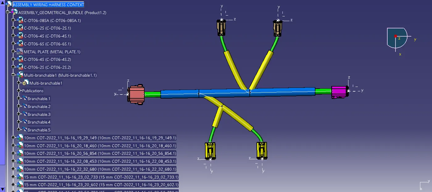
Electrical Harness Flattening:
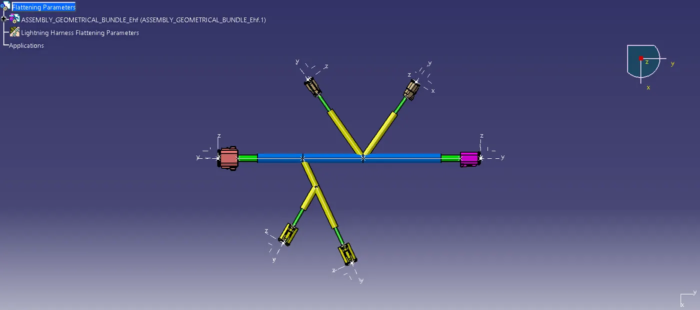
The product file is flattened using Electrical harness flattening workbench. The product is extracted using extract command and tools such as rotate, roll are used for flattening.
2D Drawing:
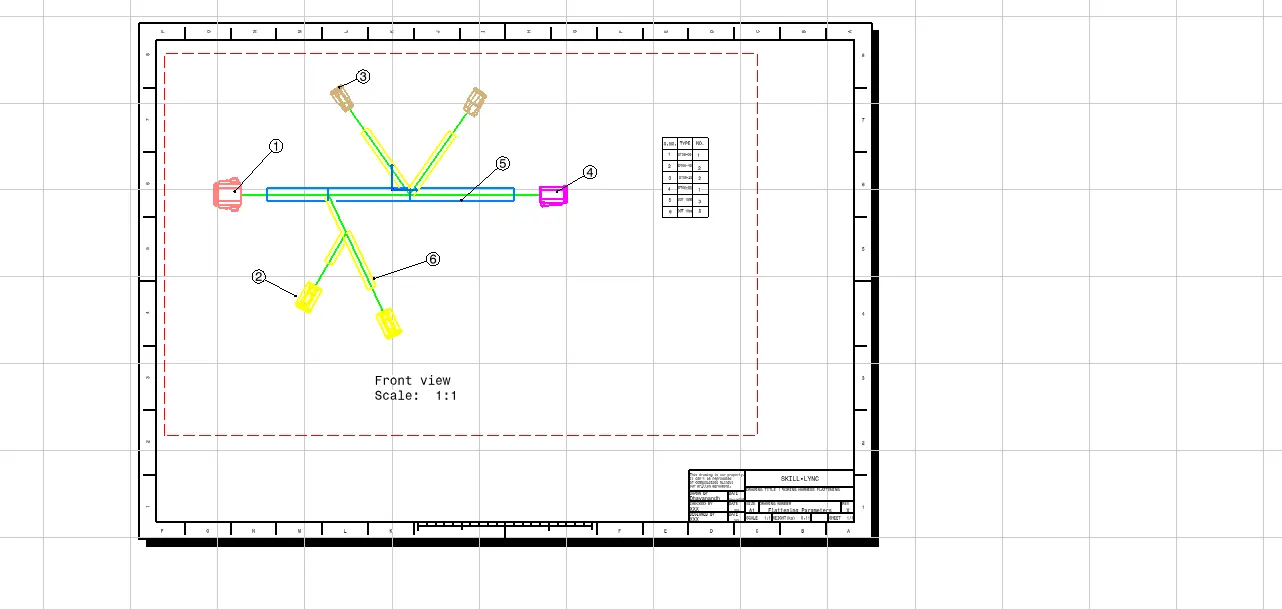
The Electrical harness flattening is drafted in drawing sheet. The flattening is represented in particular coclors and the connectors are represented using balloon features.