Wiring harness design in CATIA V5 - 3D modeling Week 5 & 6 Challenge
AIM
- Route two electrical harnesses as per the given layout and interconnect them as a single harness assembly and then check for bundle continuity, bundle warnings, and then give annotations to the final harness assembly.
OBJECTIVE
- he objective of this project is to first route the two Harness A and Harness B as per the given harness layout.
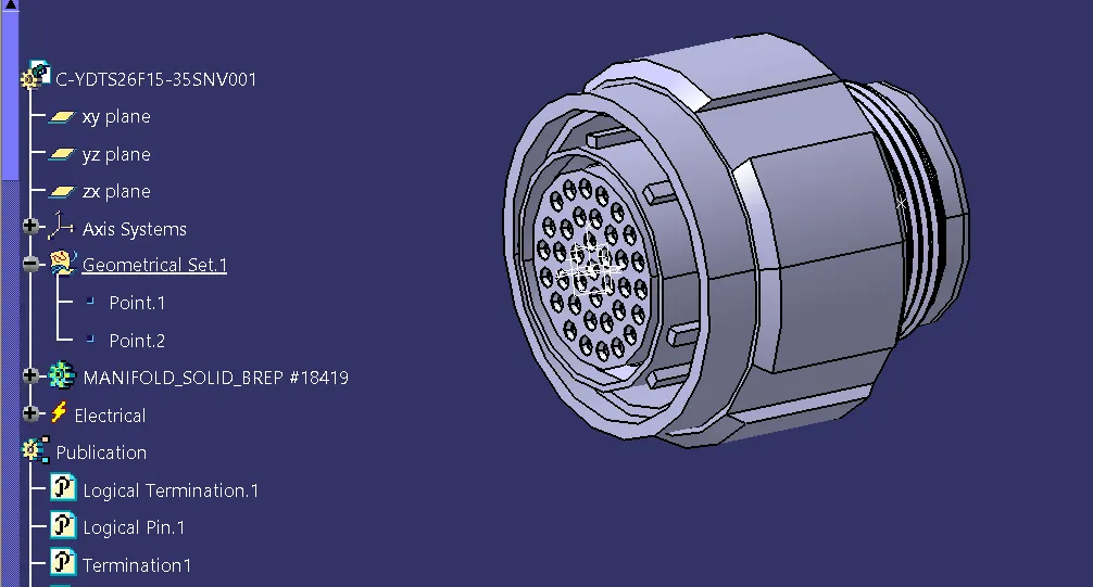
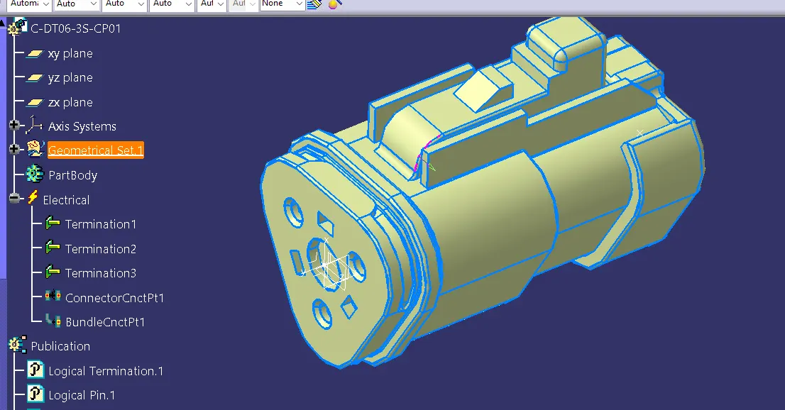
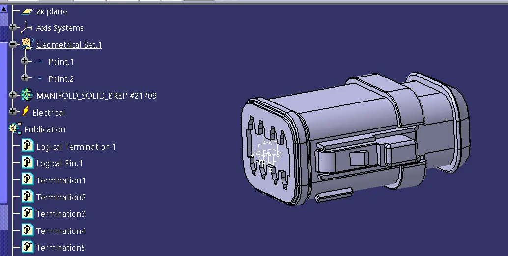
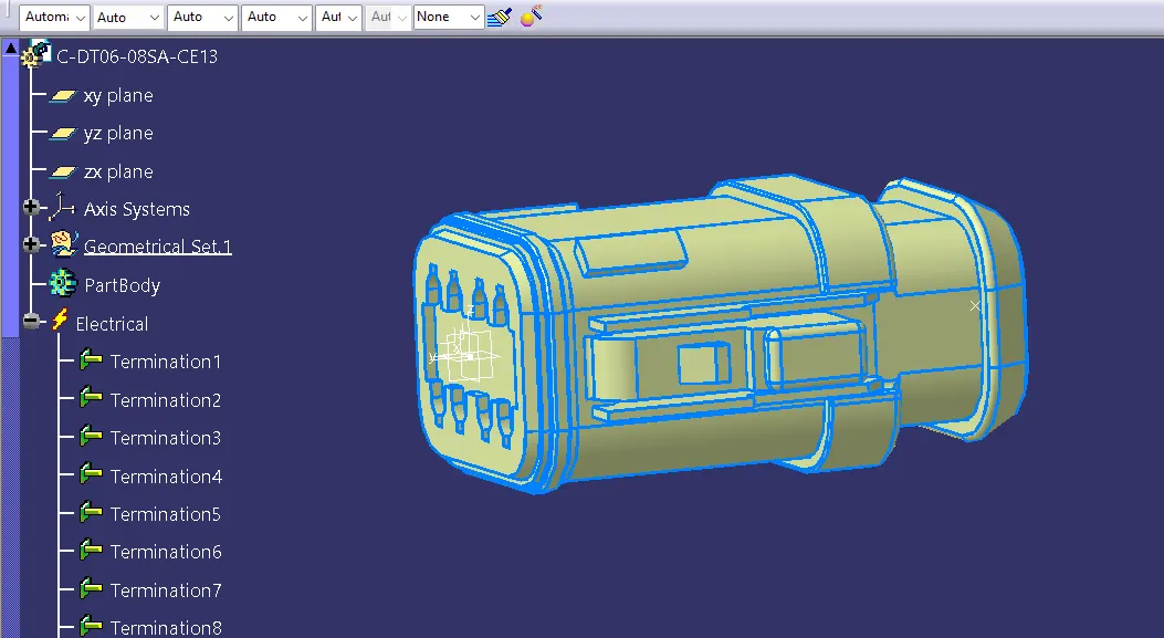
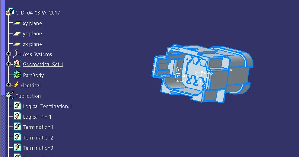
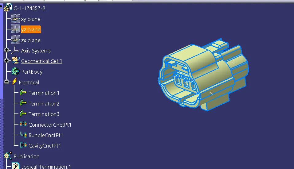
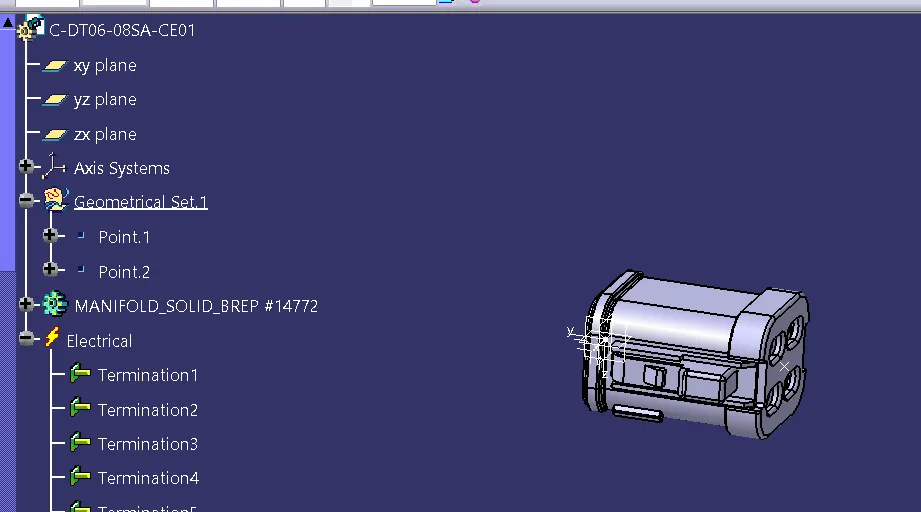
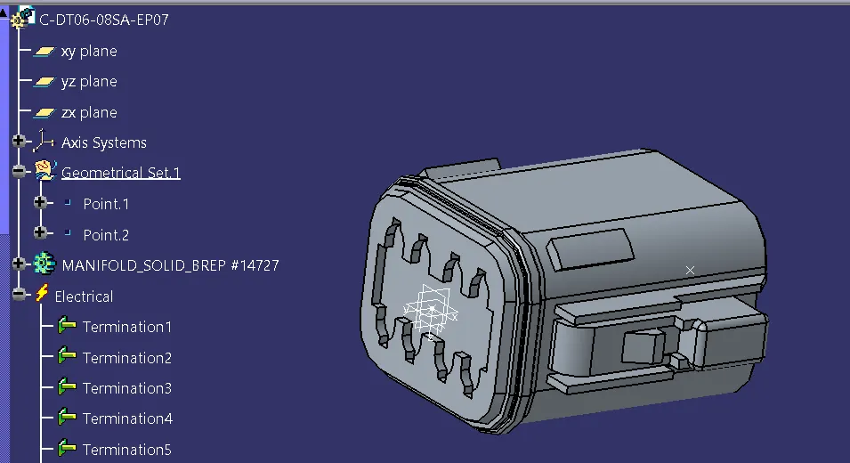
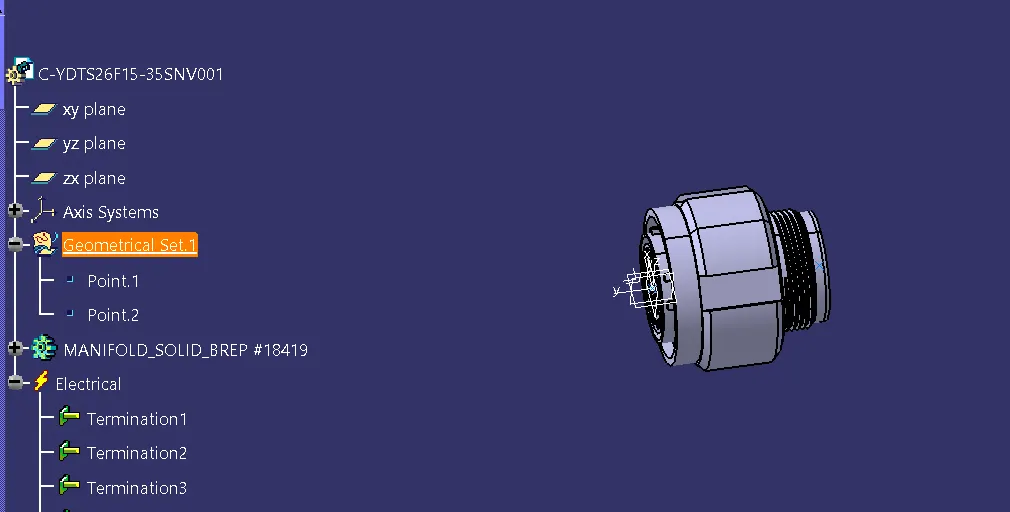
Step 1: We have to first define all the connectors geometrically and electrically as shown in below images.
Step 2:
- Now, we have to create Harness A and Harness B by using electrical harness assembly as shown in below image.
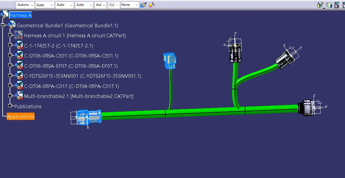
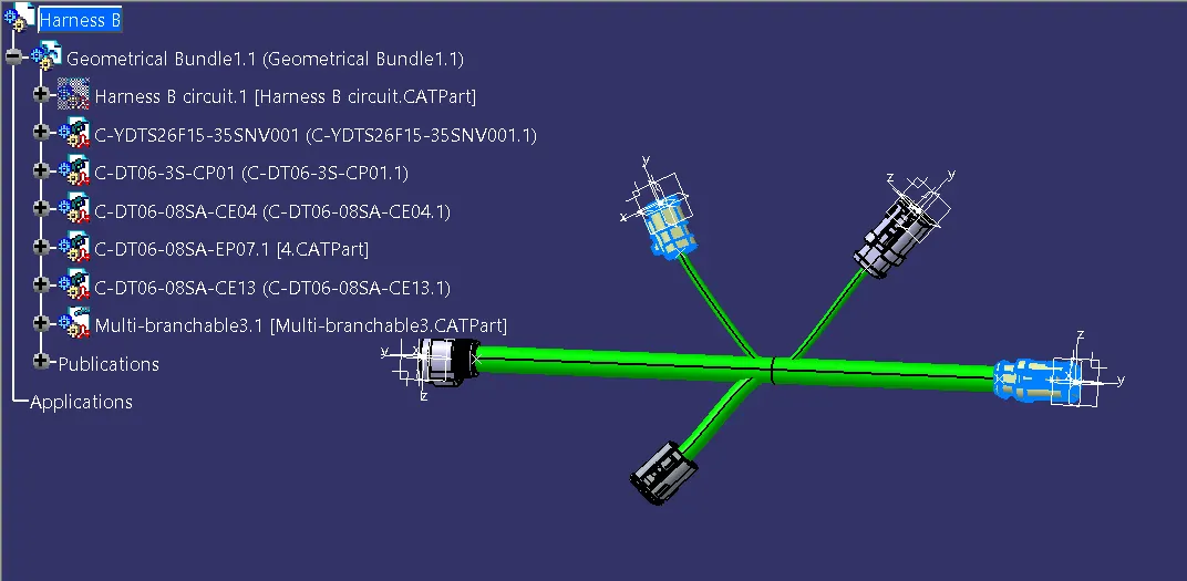
- First, we will locate all the connectors at their desired position, add branch points required and create bundle segment according to the diameters.
HARNESS A ROUTING
HARNESS B ROUTING
Step 3:
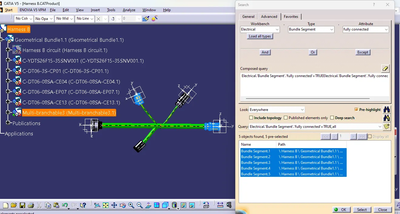
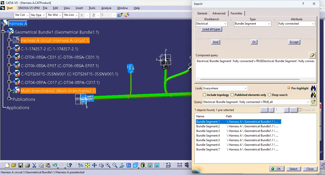
- Now in this step, we have to check bundle continuity in both Harness A and Harness B.
- So for that, go in Edit>Search>Workbench-Electrical>Type-Bundle segment>Attribute-fully connected.
- We will get one window, in that selecting True option will show all the connected bundle segments while selecting False option will show all the non-connected bundle segments.
- Now, we will check for True condition and search for result.
- All the bundle segments are showing connected. So there is bundle continuity in both Harness A & Harness B as shown in below images.
Step 4:
- In this step, we have to interconnect both Harness A & Harness B.
- For that, we have to create new product file and can give name as Assembly.
- Then, copy both harnesses and paste it in newly created product file or call both harnesses in mechanical assembly design as below image.
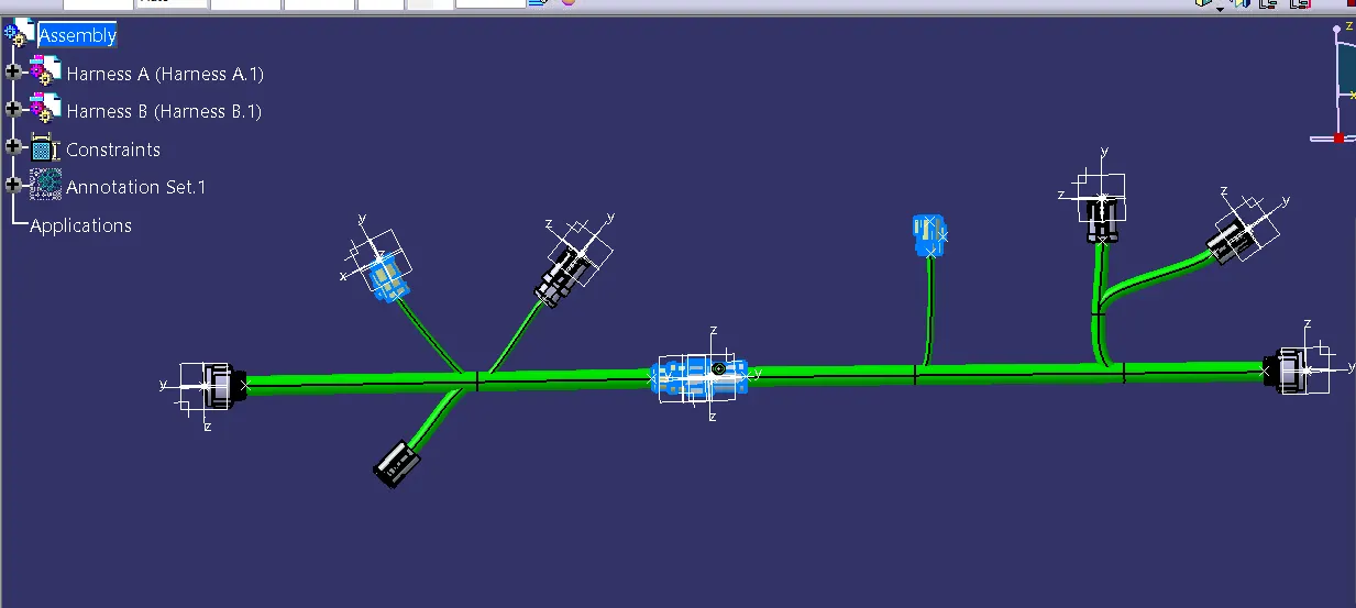
- As shown in below image, male connector should have to be inserted into the female connector.
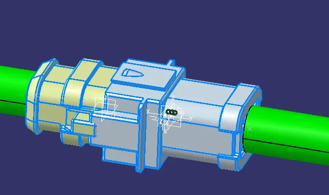
Step 6:
- In this step, we have to add annotations for all the connectors in mechanical assembly design workbench.
- Annotations are used for giving connector name, functions etc
- So after giving annotations to all connectors, the whole assembly will look as below.
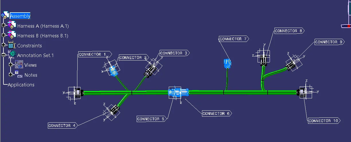
Step 7:
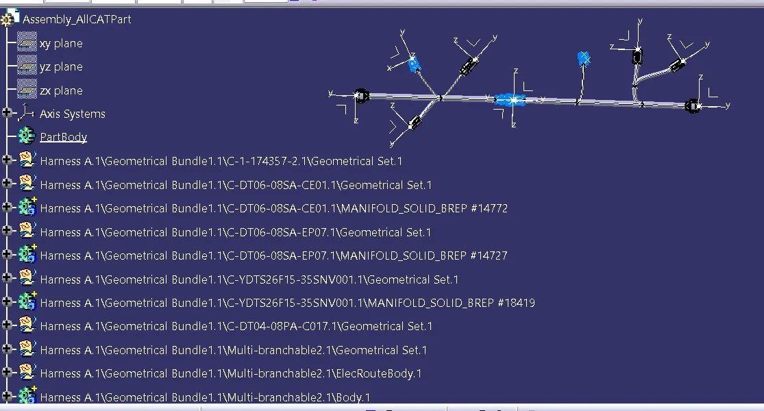
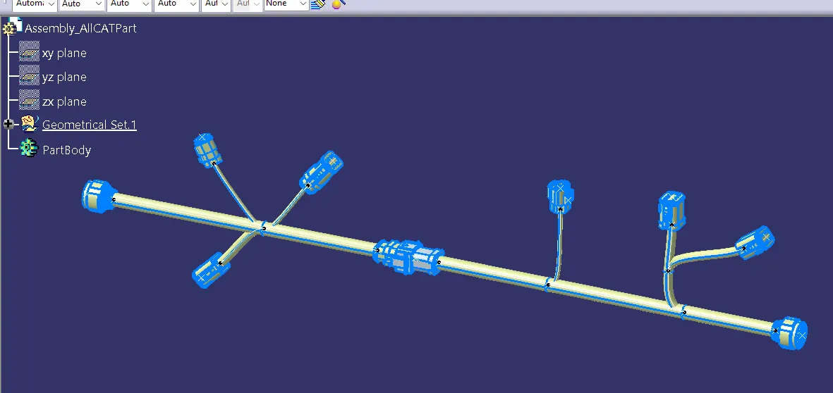
- Now, in this step we have to convert final harness assembly file into IGS format. So for that we need to follow below steps.
- Mechanical Assembly Design workbench>Tools>Generate CAT Part from product.
- Once the CAT part is created, the whole product file is converted into a single part.