Wiring harness design in CATIA V5 - 3D modeling Week 5 & 6 Challenge
The objective of this project is to first route the two Harness A and Harness B as per the given harness layout.
The electrical connectors are represented by numbers in the above figure. There are 8 different types of connectors at 10 different locations.
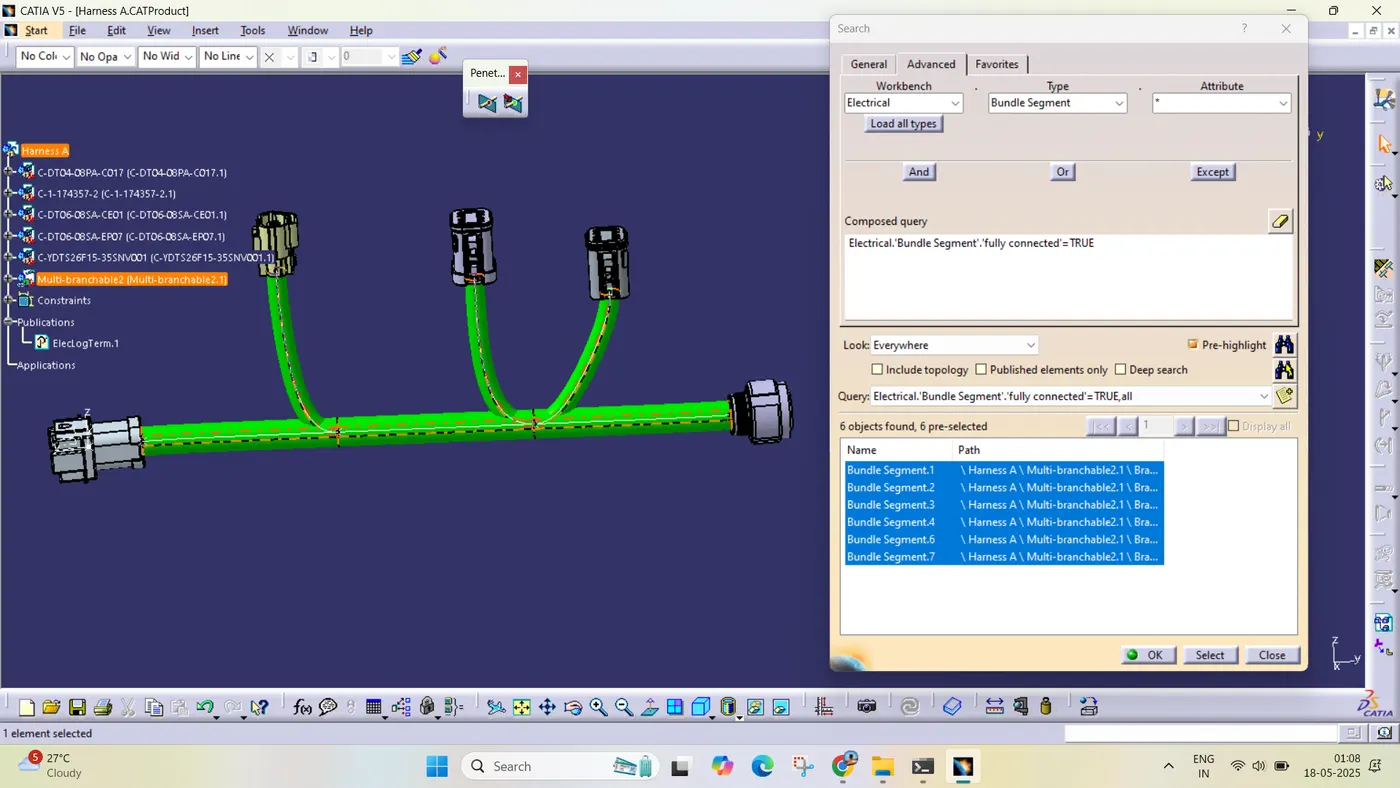
- Bundle continuity has to be checked for the two created harnesses.
- After the two Harnesses are created, the next objective is to have them interconnected electrically.
- Check for bundle warnings in Harness A and Harness B.
- Add annotations to all the connectors in Harness A and Harness B.
Define all the electrical connectors geometrically and electrically so that they can be used in the wiring harness.
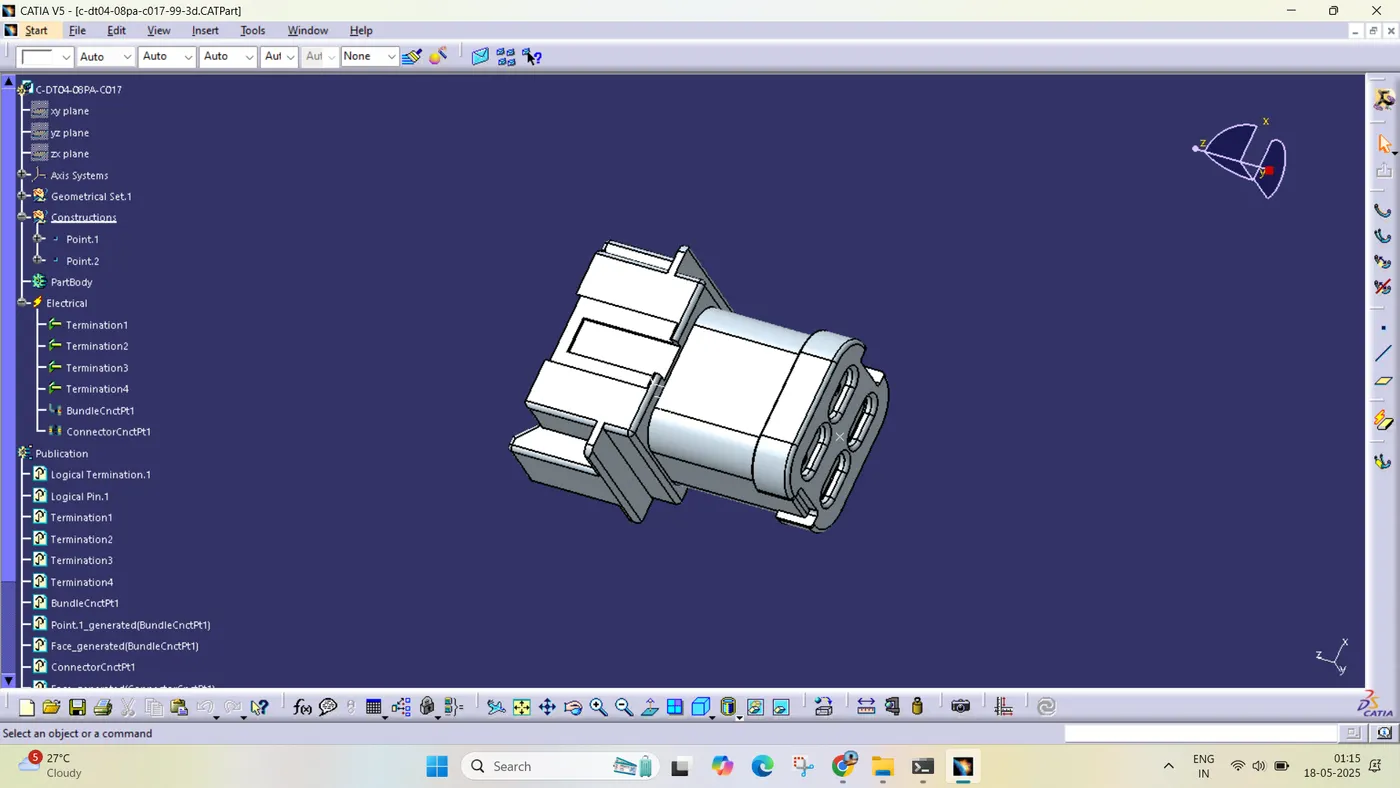
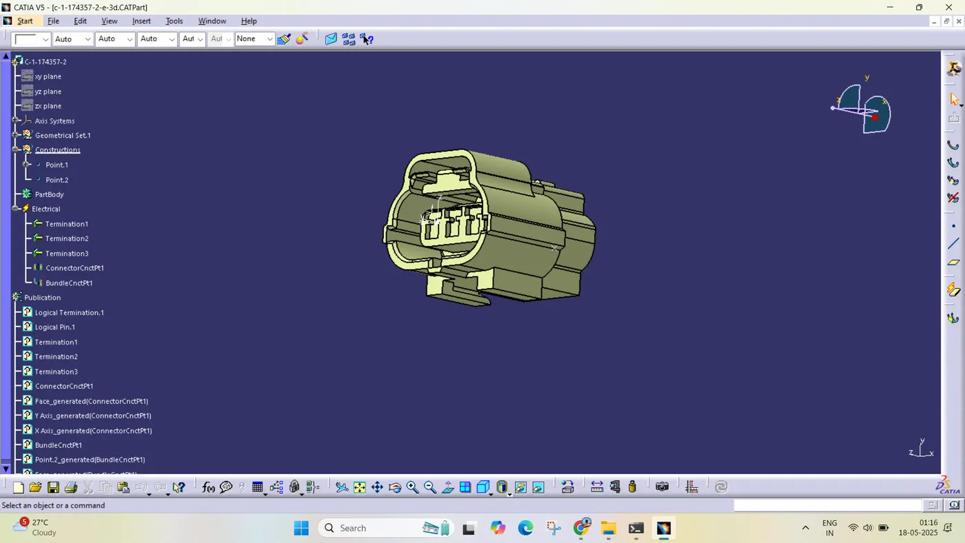
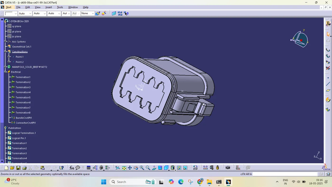
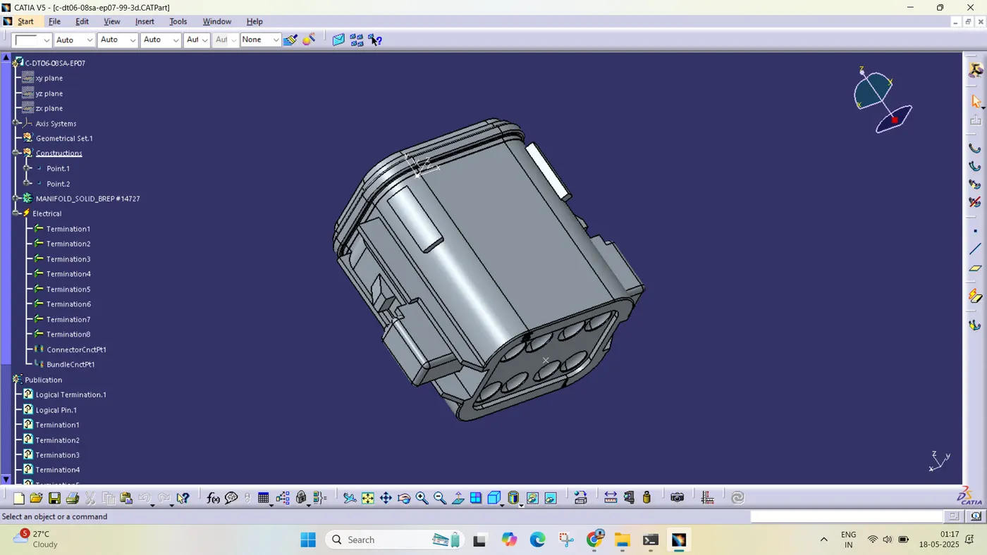
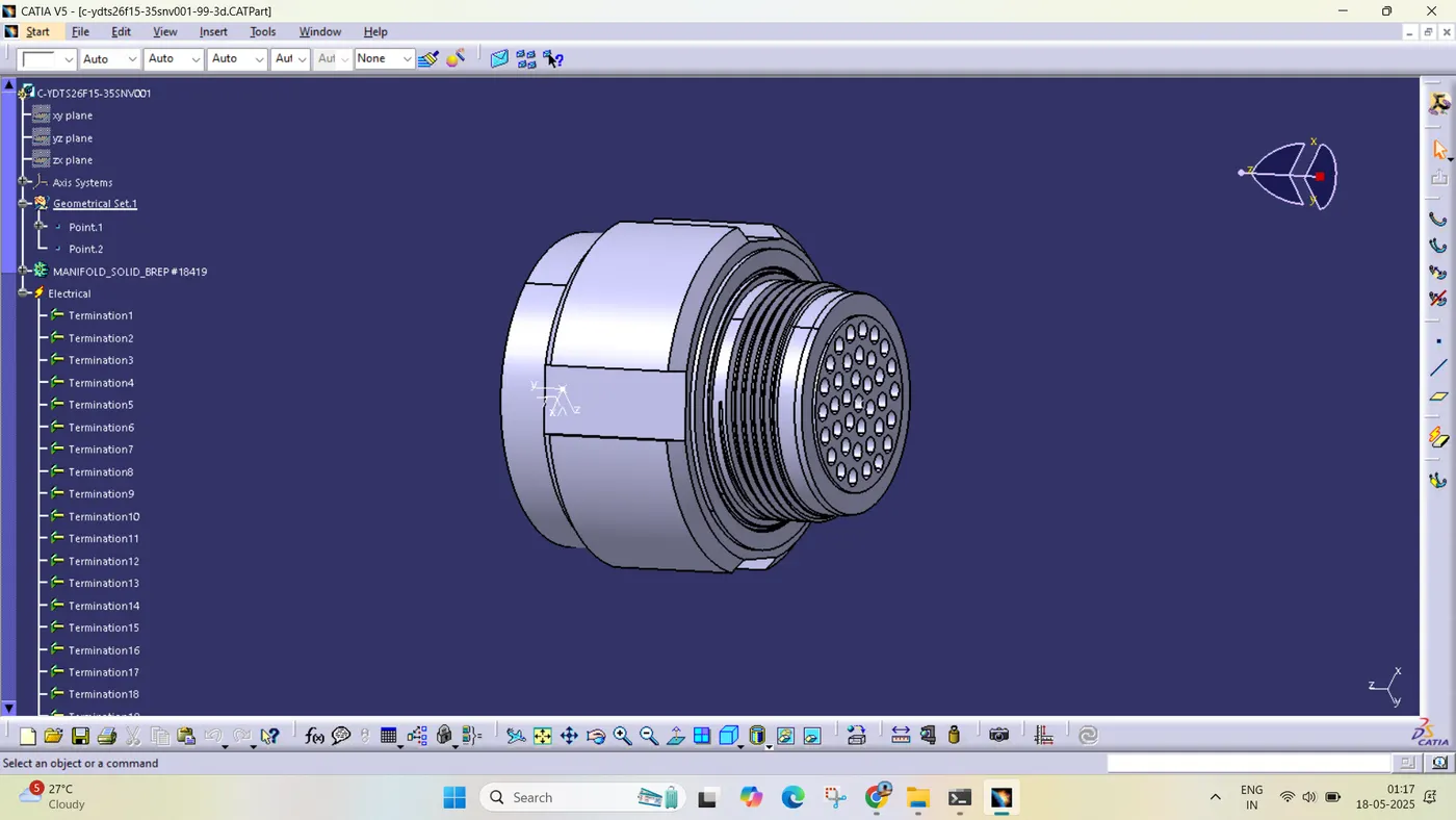
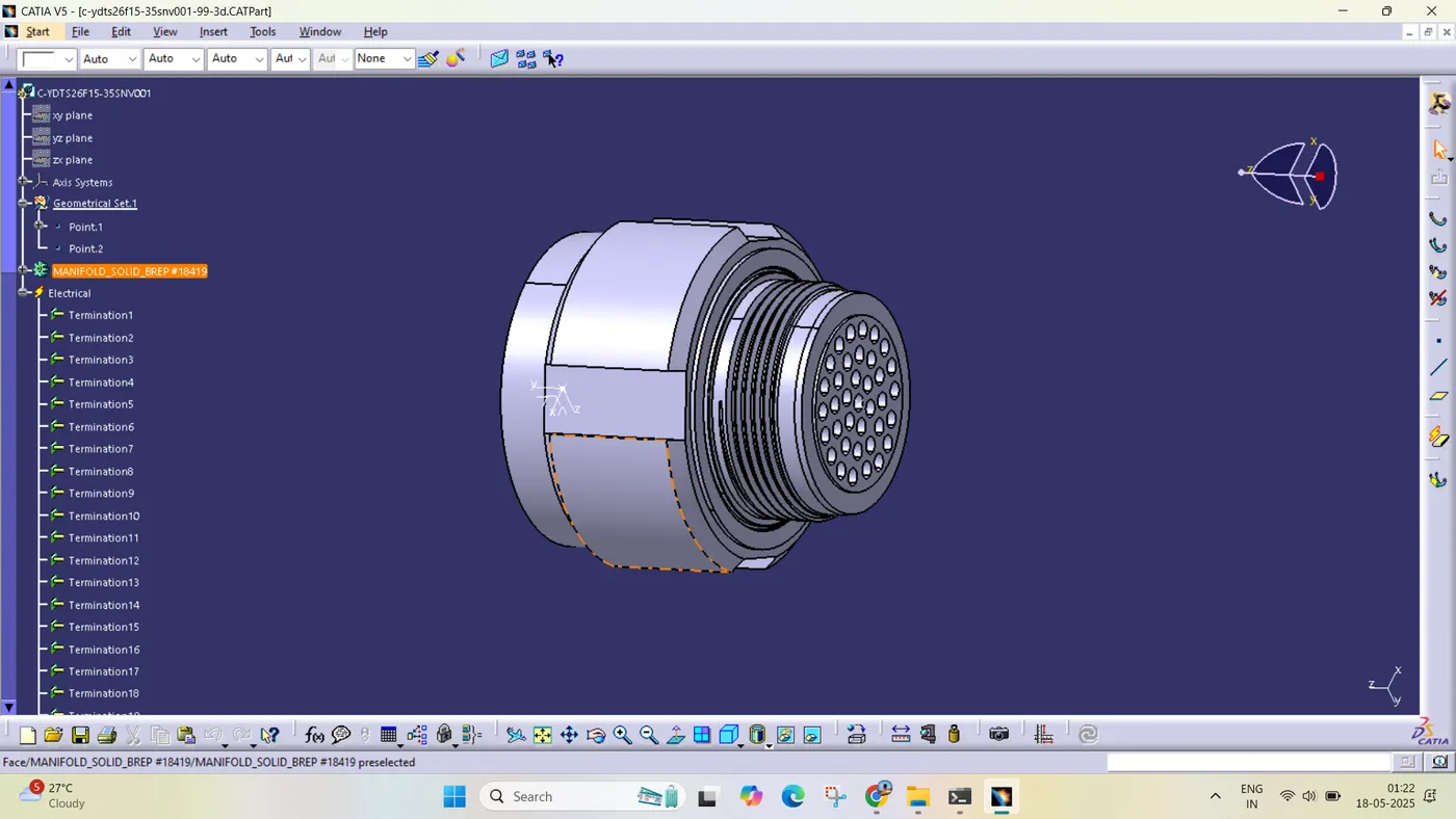
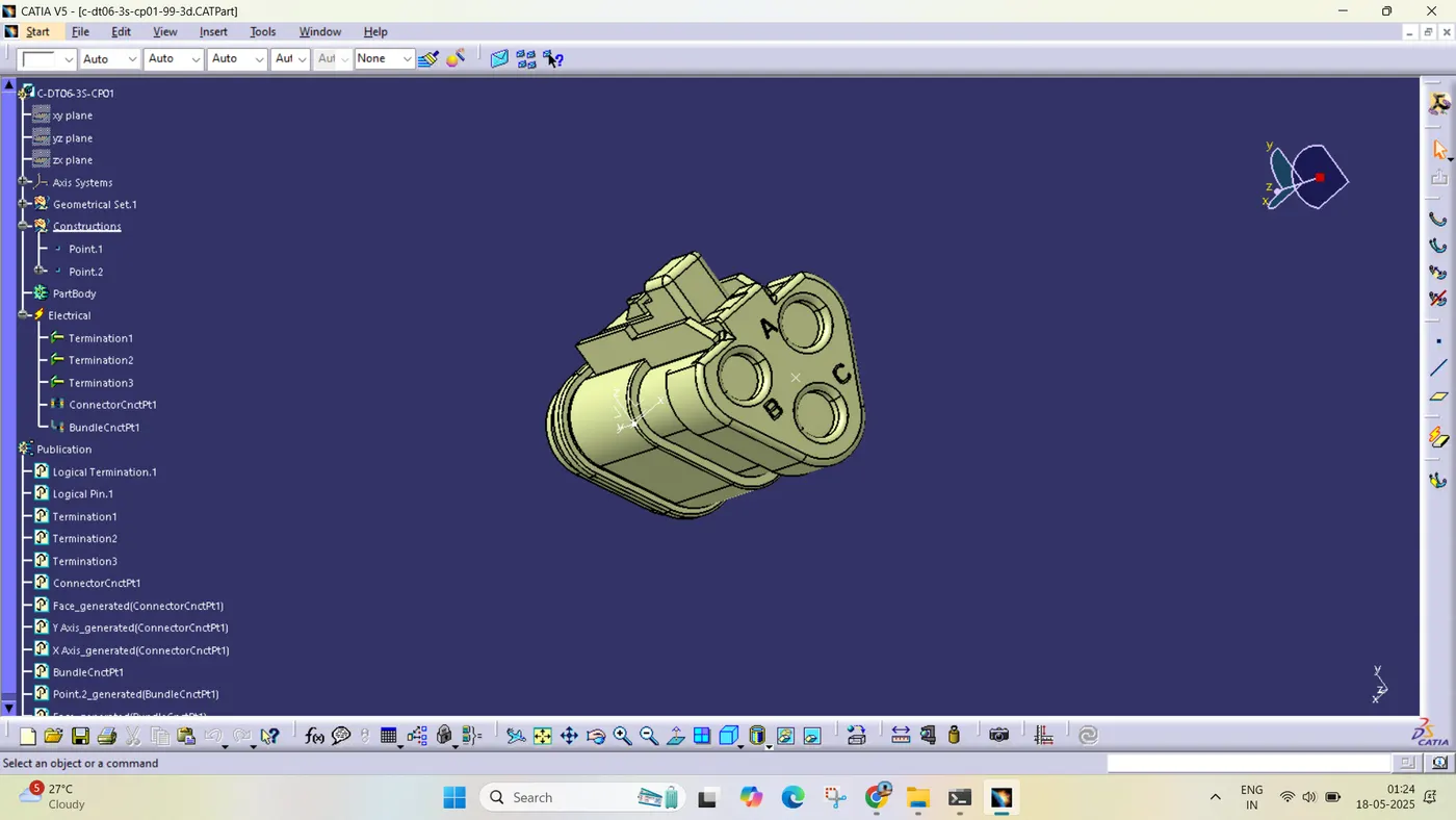
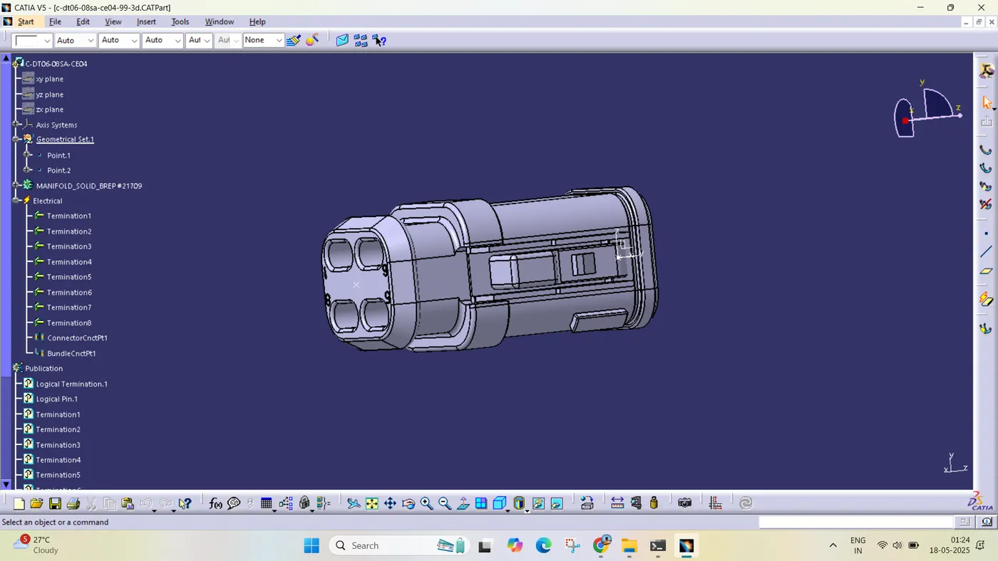
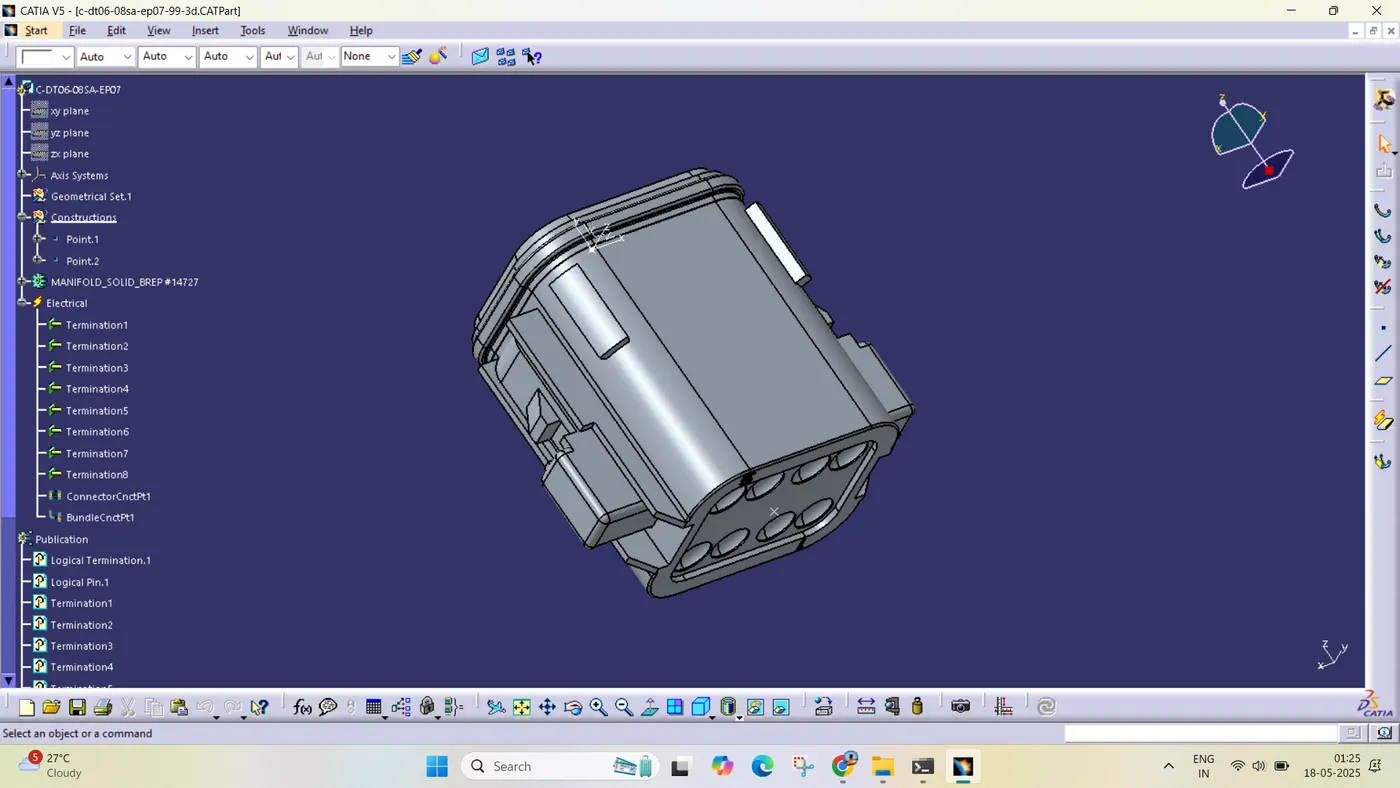
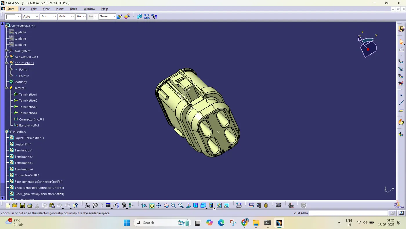
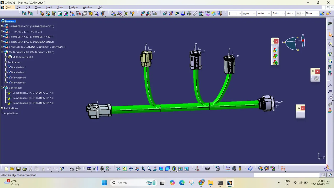
After all the connectors are defined, the workbench was switched to Electrical Harness Assembly where Geometrical Bundle was activated. All the connectors were routed using the Multi-Branchable Document command.
HARNESS A:-
HARNESS B:-
After all the connectors are defined, the workbench was switched to Electrical Harness Assembly where Geometrical Bundle was activated. All the connectors were routed using the Multi-Branchable Document command.
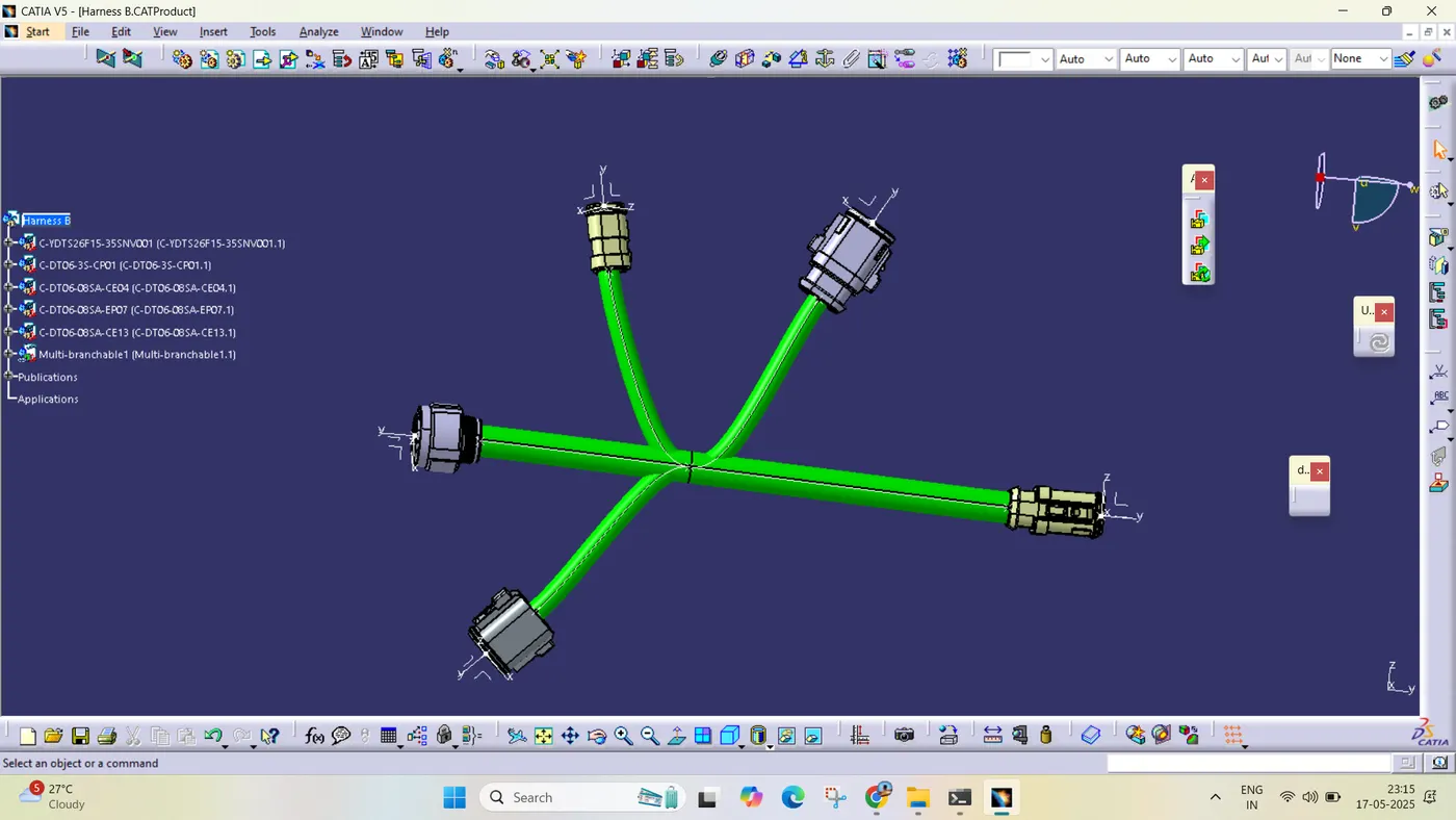
HARNESS ASSEMBLY:-
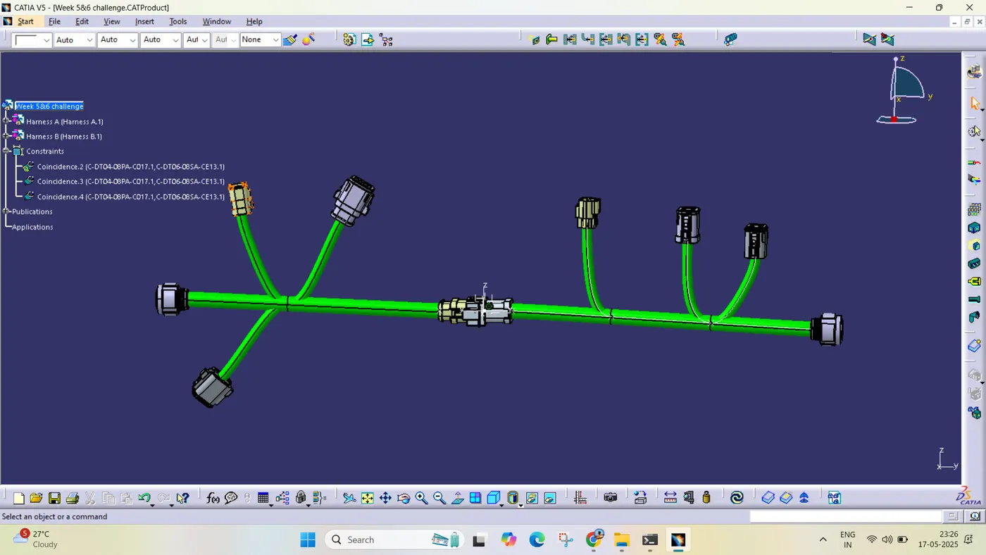
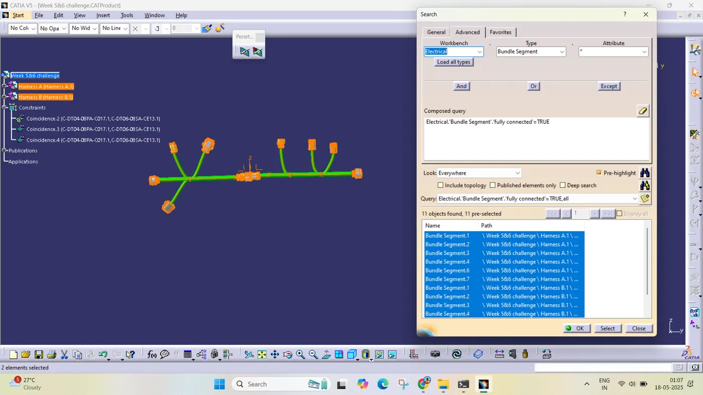
CONNECTIVITY CHECK :-
HARNESS A:-
HARNESS B:-
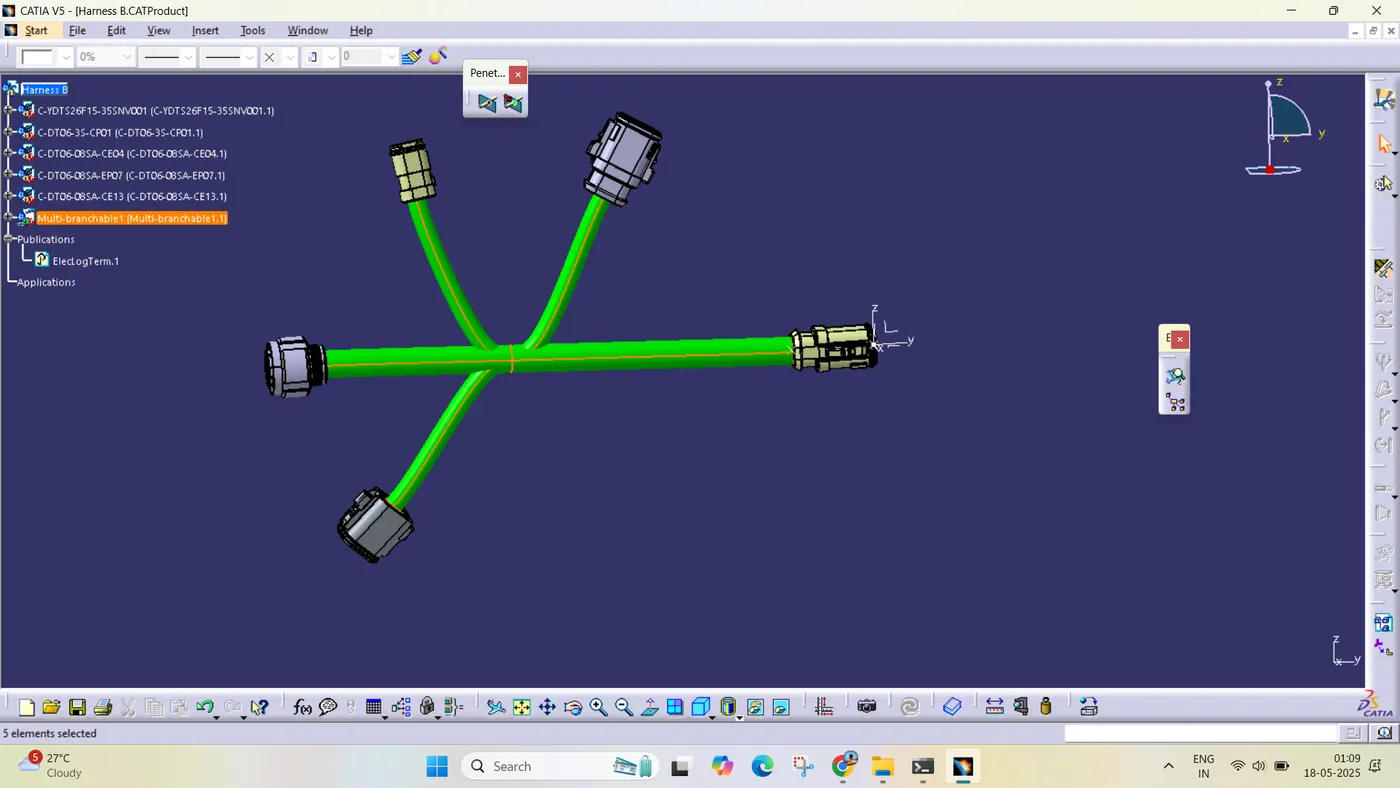
ASSEMBLY CONNECTIVTY CHECK:-