Wiring harness design in CATIA V5 - 3D modeling Week 5 & 6 Challenge
Route the following harness layout in Electrical workbench
Harness A
C-1-174357-2
Import the file from the given link and open it in mechanical part design
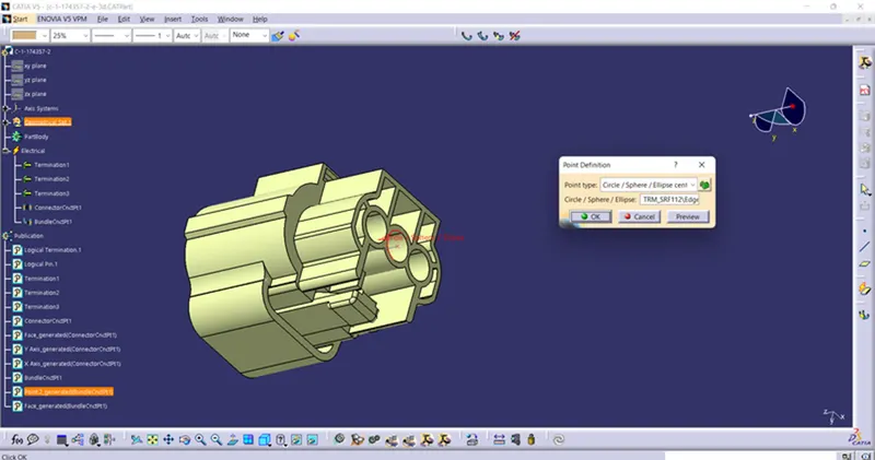
Then defined points on the connector side and bundle side.
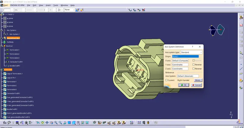
Now defined the axis system on the connector end and maintain the y-axis coincidence side.
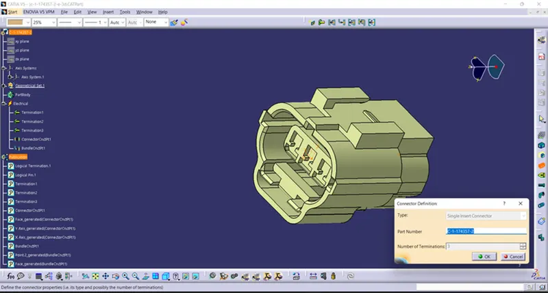
Change mechanical part workbench to electrical part workbench defined the model as a connector.
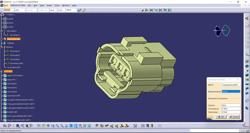
The connector end side is defined as the connector connection point.
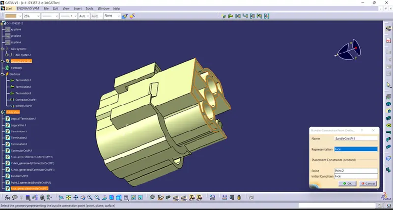
The bundle connects end is defined as a bundle connection point.
C-DT06-08SA-CE01
Import the file from the given link and open it in mechanical part design
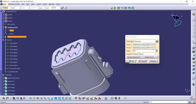
Then defined points on the connector side and bundle side.
Now defined the axis system on the connector end and maintain the y-axis coincidence side.
Change mechanical part workbench to electrical part workbench defined the model as a connector.
The connector end side is defined as the connector connection point.
The bundle connects end is defined as a bundle connection point.
C-DT06-08SA-EP07
Import the file from the given link and open it in mechanical part design
Then defined points on the connector side and bundle side.
Now defined the axis system on the connector end and maintain the y-axis coincidence side.
Change mechanical part workbench to electrical part workbench defined the model as a connector.
The connector end side is defined as the connector connection point.
The bundle connects end is defined as a bundle connection point.
C--YDTS26F-15-35SNV001
Import the file from the given link and open it in mechanical part design
Then defined points on the connector side and bundle side.
Now defined the axis system on the connector end and maintain the y-axis coincidence side.
Change mechanical part workbench to electrical part workbench defined the model as a connector.
The connector end side is defined as the connector connection point.
The bundle connects end is defined as a bundle connection point.
C-DT04-08PA-C017
Import the file from the given link and open it in mechanical part design
Then defined points on the connector side and bundle side.
Now defined the axis system on the connector end and maintain the y-axis coincidence side.
Change mechanical part workbench to electrical part workbench defined the model as a connector.
The connector end side is defined as the connector connection point.
The bundle connects end is defined as a bundle connection point.
Harness A Assy
Opened a new product file in mechanical assembly and imported all the connectors.
All the connectors were placed as per the given flow chart with help of manipulation.
Now changed mechanical assembly to electrical harness assembly. Opened multi branchable started routing between the connectors.
Created branch point for creating Sub-branch.
With help of the branch, points were created from sub-branches from the main branch. Connected all the connectors.
No Bundle Warning Found in Tree.
Bundle Continuity Check Found Ok.
Harness B
C-DT06-3S-CP01
Import the file from the given link and open it in mechanical part design.
Then defined points on the connector side and bundle side.
Now defined the axis system on the connector end and maintain the y-axis coincidence side.
Change mechanical part workbench to electrical part workbench defined the model as a connector.
The connector end side is defined as the connector connection point.
The bundle connects end is defined as a bundle connection point.
C-DT06-08SA-CE04
Import the file from the given link and open it in mechanical part design.
Then defined points on the connector side and bundle side.
Now defined the axis system on the connector end and maintain the y-axis coincidence side.
Change mechanical part workbench to electrical part workbench defined the model as a connector.
The connector end side is defined as the connector connection point.
The bundle connects end is defined as a bundle connection point.
C-DT06-08SA-CE13
Import the file from the given link and open it in mechanical part design.
Then defined points on the connector side and bundle side.
Now defined the axis system on the connector end and maintain the y-axis coincidence side.
Change mechanical part workbench to electrical part workbench defined the model as a connector.
The connector end side is defined as the connector connection point.
The bundle connects end is defined as a bundle connection point.
C-DT06-08SA-EP07
Import the file from the given link and open it in mechanical part design.
Then defined points on the connector side and bundle side.
Now defined the axis system on the connector end and maintain the y-axis coincidence side.
Change mechanical part workbench to electrical part workbench defined the model as a connector.
The connector end side is defined as the connector connection point.
The bundle connects end is defined as a bundle connection point.
C-YDTS26F15-35SNV001
Import the file from the given link and open it in mechanical part design.
Then defined points on the connector side and bundle side.
Now defined the axis system on the connector end and maintain the y-axis coincidence side.
Change mechanical part workbench to electrical part workbench defined the model as a connector.
The connector end side is defined as the connector connection point.
The bundle connects end is defined as a bundle connection point.
Harness B Assy
Opened a new product file in mechanical assembly and imported all the connectors.
All the connectors were placed as per the given flow chart with help of manipulation.
Now changed mechanical assembly to electrical harness assembly. Opened multi branchable started routing between the connectors.
Created branch point for creating Sub-branch.
With help of the branch, points were created from sub-branches from the main branch. Connected all the connectors.
No Bundle warning in the tree. Bundle connection found Ok.
Bundle Continuity Found ok no disconnectivity
Harness A and B Assy
Opened a new product file in electrical assembly. Imported Harness A and B in the Product file.
Connected harness A and B with help of connect electrical device.
checked For disconnectivity with FALSE not found any disconnectivity.
checked For disconnectivity with TRUE not found any disconnectivity.
Added plane for Annotation with connector reference.
Given annotations For all the connectors.
Cot made for sub-branches.
Converting the file product file to the part file.
Convert to part file.
File converted Part file to igs file too.