Wiring harness design in CATIA V5 - 3D modeling Week 5 & 6 Challenge
HARNESS B1
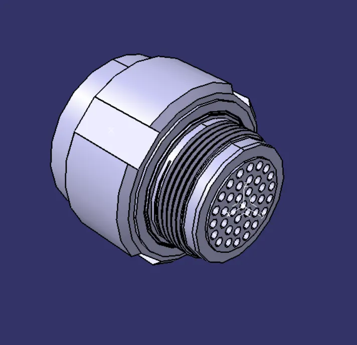
- Create two points both sides.
-Create the axis
-Open the Electrical Part Design
-Define the bundle connection point
-Define connnector connection point
HARNESS B2
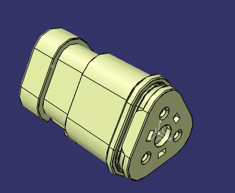
- Create two points both sides.
-Create the axis
-Open the Electrical Part Design
-Define the bundle connection point
-Define connnector connection point
HARNESS B3
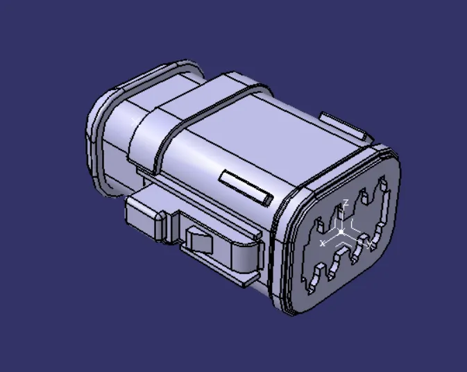
- Create two points both sides.
-Create the axis
-Open the Electrical Part Design
-Define the bundle connection point
-Define connnector connection point
HARNESS B4
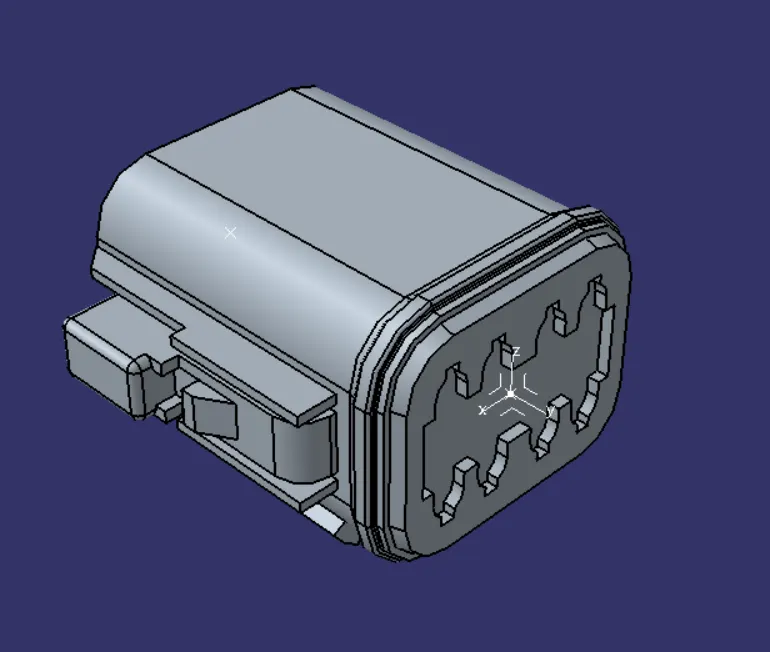
- Create two points both sides.
-Create the axis
-Open the Electrical Part Design
-Define the bundle connection point
-Define connnector connection point
HARNESS B5
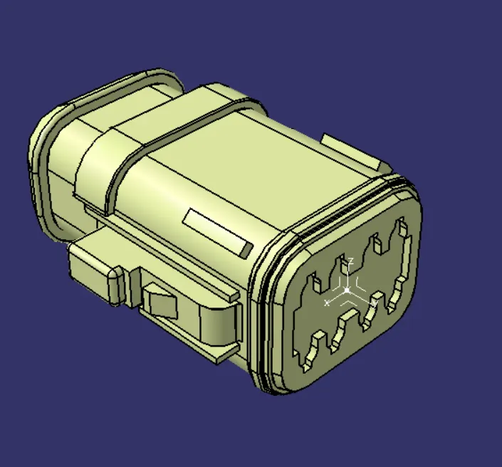
- Create two points both sides.
-Create the axis
-Open the Electrical Part Design
-Define the bundle connection point
-Define connnector connection point
HARNESS A6
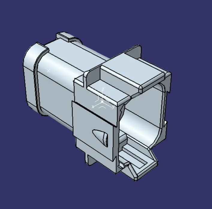
- Create two points both sides.
-Create the axis
-Open the Electrical Part Design
-Define the bundle connection point
-Define connnector connection point
HARNESS A7
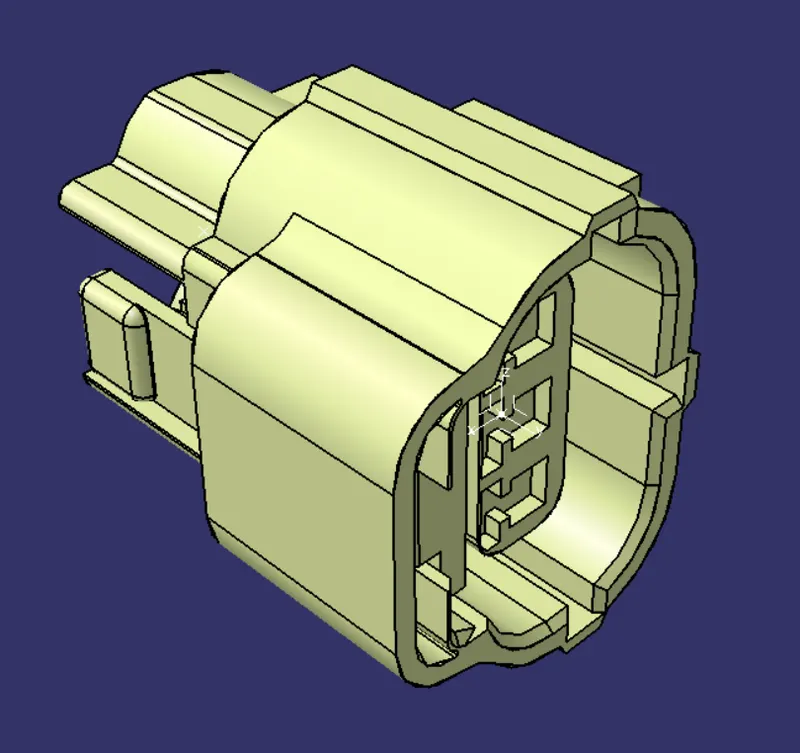
- Create two points both sides.
-Create the axis
-Open the Electrical Part Design
-Define the bundle connection point
-Define connnector connection point
HARNESS A8
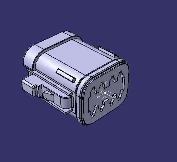
- Create two points both sides.
-Create the axis
-Open the Electrical Part Design
-Define the bundle connection point
-Define connnector connection point
HARNESS A9
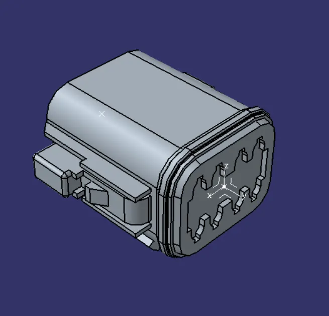
- Create two points both sides.
-Create the axis
-Open the Electrical Part Design
-Define the bundle connection point
-Define connnector connection point
HARNESS A10
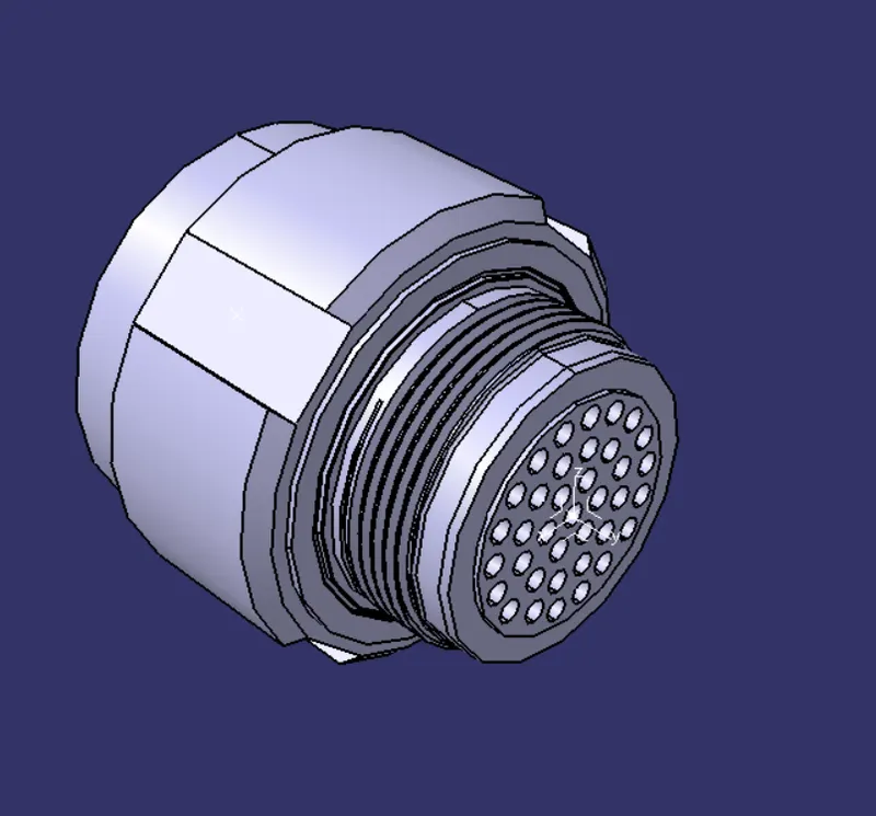
- Create two points both sides.
-Create the axis
-Open the Electrical Part Design
-Define the bundle connection point
-Define connnector connection point
HARNESS B ASSEMBLY
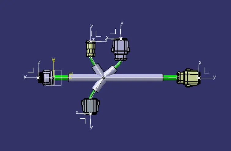
-Create a reference line so to use connections by using Multi-Branchable
-Before that,define all the products as Geometrical Bundle
-Connect the Electrical parts each other as reference lines are shown
-After that,cover the connections by using Protective Covering
HARNESS A ASSEMBLY
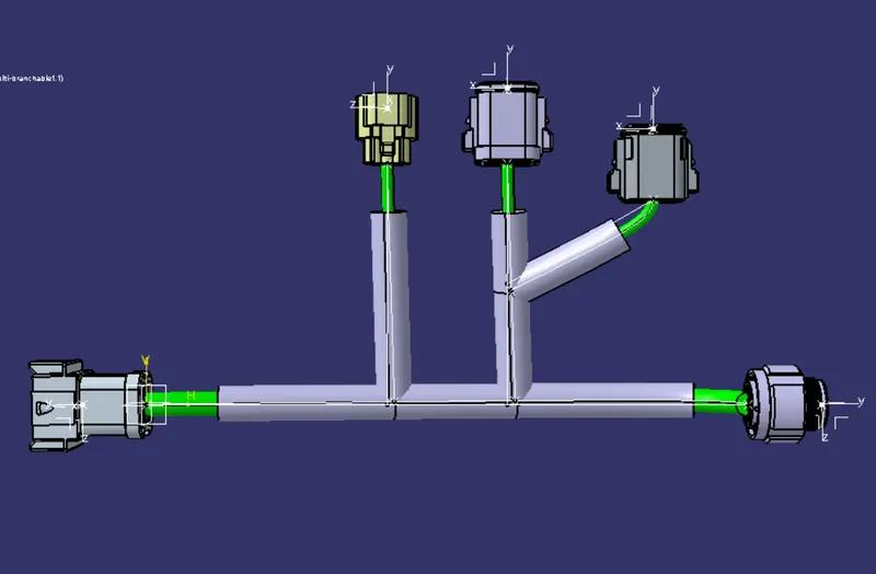
-Create a reference line so to use connections by using Multi-Branchable
-Before that,define all the products as Geometrical Bundle
-Connect the Electrical parts each other as reference lines are shown
-After that,cover the connections by using Protective Covering
HARNESS ASSEMBLY A&B
- Place two assemblies Harness A and Harness B in the Assembly Design
-Connect a point from Harness A to a point from Harness B by using snap command