Wiring harness design in CATIA V5 - 3D modeling Week 5 & 6 Challenge
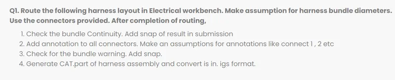
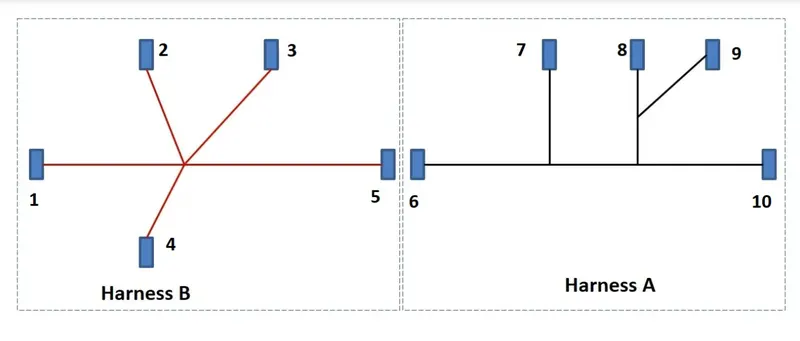
Steps for how to create the harness assemblies and bundle contnuity check
step 1; downloading the connectors by a given link
step 2; open them in to catia v5 by changing the stp and igs file into the part file
step 3; creating the required geometric parameters by part design workbench
step 4; switch the part design into electrical part design
step 5; define the bundle connecter cavity points as well as
step 6; by defining these characters to change the part as electrical
step 7; after defining all given parts as electrical, move or copied in to the new product assembly file
step 8; and then arrranged the posistion of connectors into given routing sketch
step 9; change the prouduct file as geometric bundle by switching the assembly design into electric harness assembly
step 10; routing the harness by creation of multi branchable documents
step 11; give routing defnitions and branch defnitions inputs into multi branchable documents
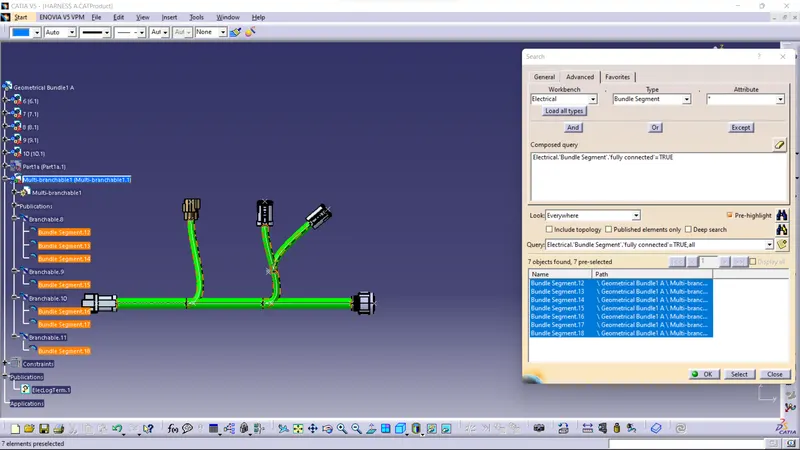
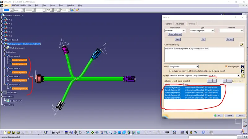
step 12; now check the bundle continuity by edit search and give inputs as shown as figure
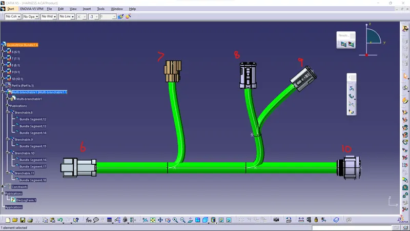
Electrical harness assembly A
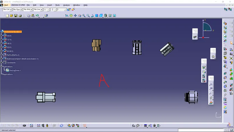
Bundle continuity of harness A
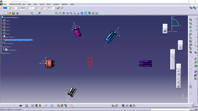
Electrical harness assembly B

Bundle continuity of harness B
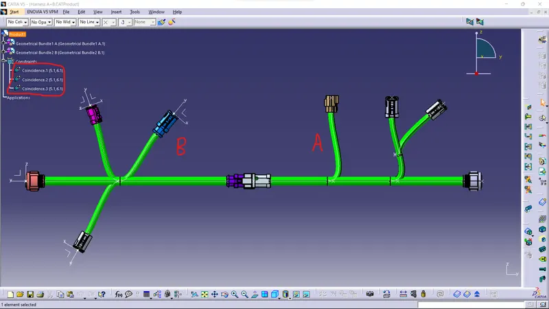
Electrical harness assembly A & B
To connect the electric harness assembly A and B opening the new file of electrical assembly design and then copy the two harness
assembly of A and B and paste into the electrical assembly design then connect the connectors of 5 & 6 by electrically by using the
command connect electrical device
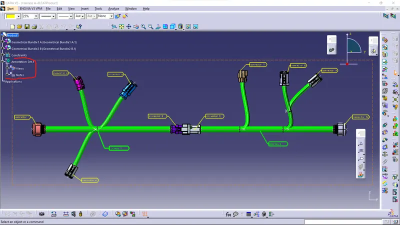
Annotations views
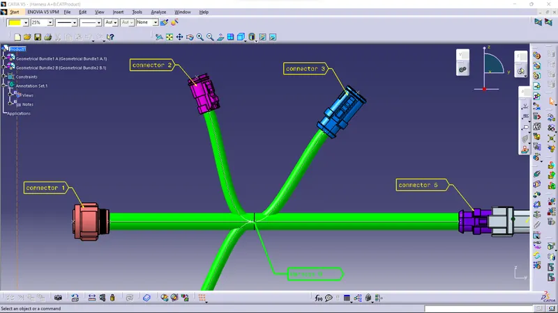
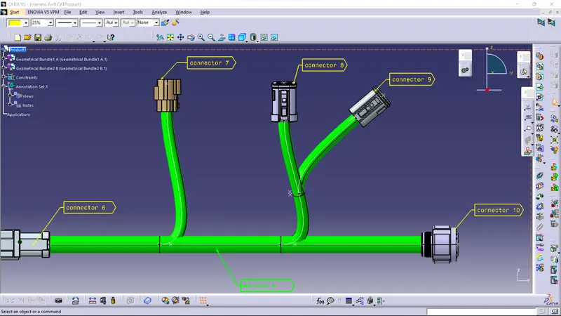
Generate CAT part from product
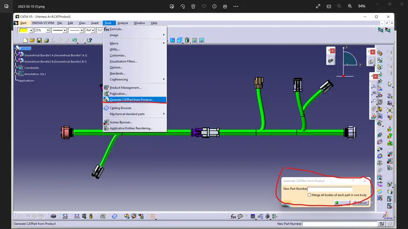
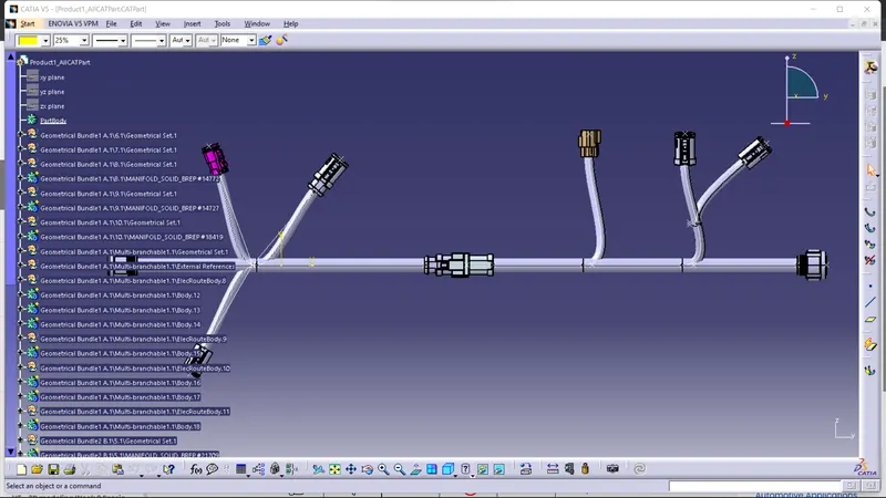
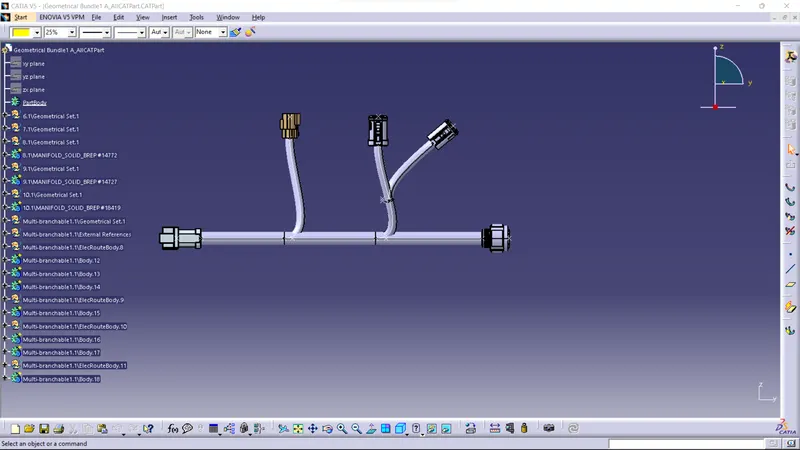
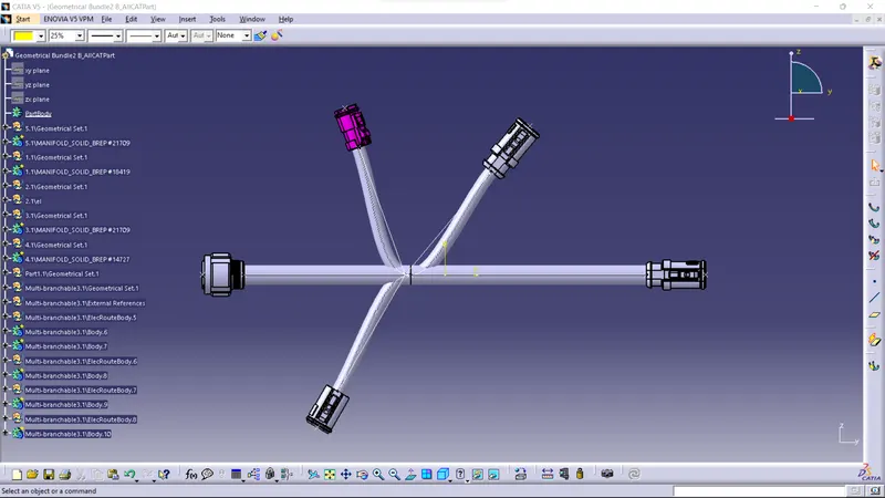
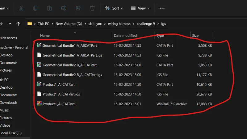
saving CAT part file into igs