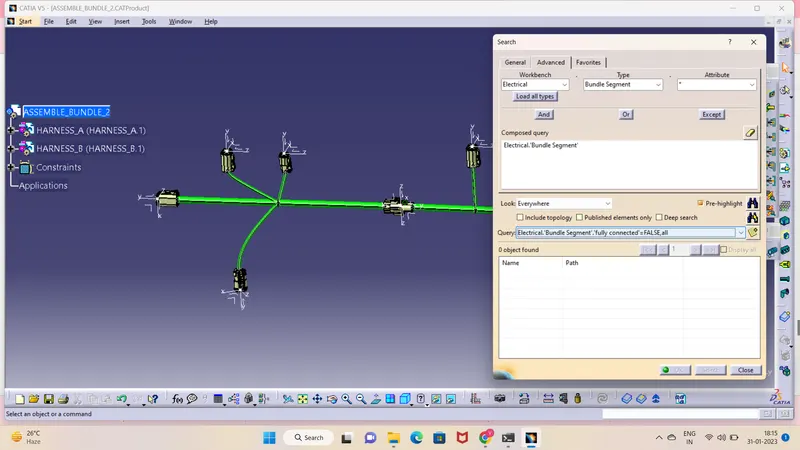
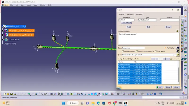
Wiring harness design in CATIA V5 - 3D modeling Week 5 & 6 Challenge
1A)Electrical definition and Catalogue creation
Mechanical connectors offer a flexible means for jointing of copper and/or aluminium sector/circular cables. They are quick and easy to install. They require no crimping - simply insert the cable and clamp with the screws or bolts supplied to achieve a highly reliable electrical connection.
A report on defining components and creating catalogue
1) Giving geometrical parameters:
- after downloading the component from the link & unzipping it, the component is opened into the catia
- to open the component in software, the steps are: file > open > select the downloaded unzipped file > press enter.
- switch the workbench into part design by clicking on start>mechanical design>part design
- in order to define the component geometrically, the commands like point, line, axis & plane are used.
- after identifying the component's connection points, select point command from the reference element toolbar displayed at the right corner of catia interface.
- place a point on both connection sides of the component keeping it as middle as possible by taking one of its geometric reference like surface, edge, circle etc.
- after that place axes on both the points by selecting axis button at the bottom toolbar and click on the point.
- after placing axes on both of the points, the orientation has to adjust.
- the axes orientation should be like: Y axis needs to be perpendicualr to the face of connector, X axis should be pointed towards the locking mechanism of the connector.
2) Defining the connector (CAD model) as a connector
- till this the connector is a CAD model. further it needs to be define as a connector.
- for this the connector should be in electrical part design workbench.
- to switch to this workbench steps are: click on start>equipment and systems>electrical harness descipline>electrical part design.
- to define the connector(CAD model) as a connector click on define connector button and click on anywhere on the connector's body. after this a window will appear on screen which will ask for no. of terminations present on the connector, fill it accordingly and say ok.
- now its time to give connector connection point and bundle connection point.
- identify the connector connection point side and prepare its orientation to define it
- to do this click on define connector connection point button present on right corner toolbar and click on the model(connector).
- after this a window will appear which will ask for representation, now select origin point after that, for contact select the face on which the axes are present. for coincidence select y axis and for orientation select x axis
- to define bundle connection point, change the orientation to the bundle connection side then click on define bundle connection point after that click on the model.
- a window will apper after this which will ask for representation, select the face on which the axes are present. then for point, select the origine point, then for initial condition select the same face and say ok.
- in this way the connector has been defined.
3) catalogue creation
- To have a catalogue of different components from the same family helps to get easy access to that perticular component while doing an assembly
- to create a catalogue go to new>catalogue document>ok
- after this a window will appear then select add family option at the right corner toolbar>give the family name>select the suitable type>ok
- then save the catalogue document. file>save>give name>ok
- to add any component in the catalogue, open that component in catia and select electrical part design workbench. select store device option>brouse the catalogue that has been saved earlier>select that catalogue>select family>ok.
- in this way the catalogue has been created and the components are stored in it
2A) HARNESS A
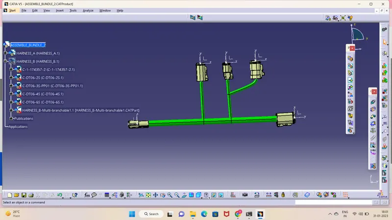
All the connectors are defined, the workbench was switched to Electrical Harness Assembly where Geometrical Bundle was activated. All the connectors were routed using the Multi-Branchable Document command.
HARNESS B
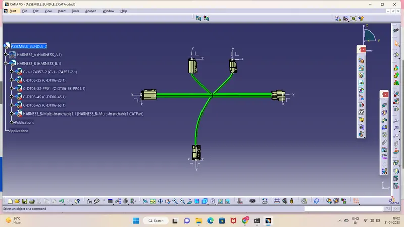
All the connectors are defined, the workbench was switched to Electrical Harness Assembly where Geometrical Bundle was activated. All the connectors were routed using the Multi-Branchable Document command.
HARNESS ASSEMBLY
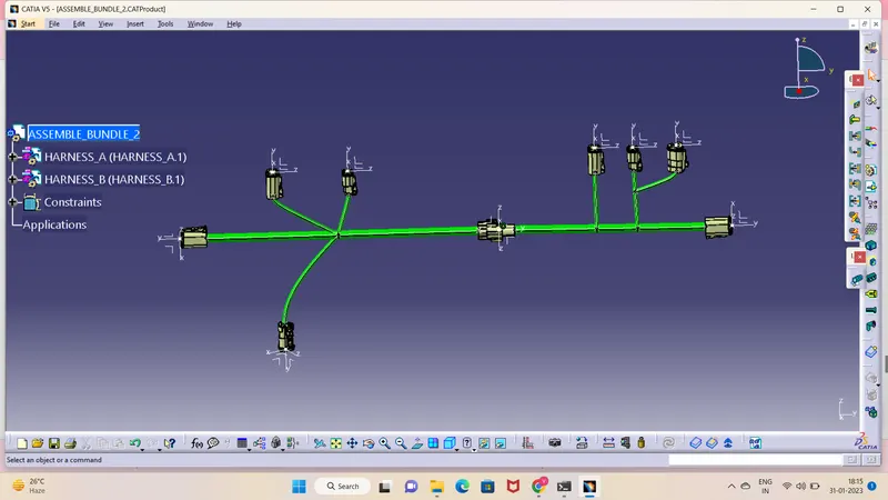
CONNECTIVITY CHECK