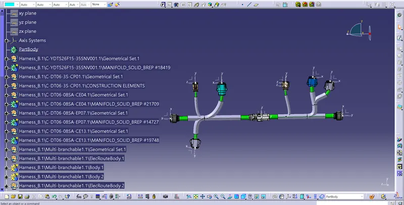
Wiring harness design in CATIA V5 - 3D modeling Week 5 & 6 Challenge
1.
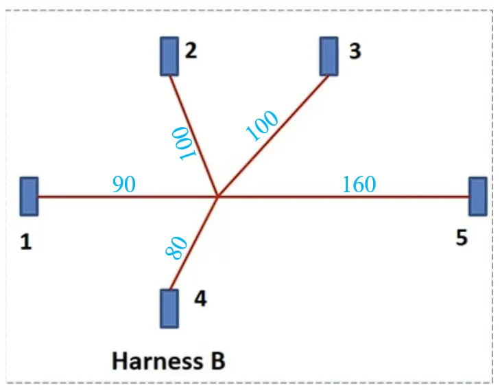
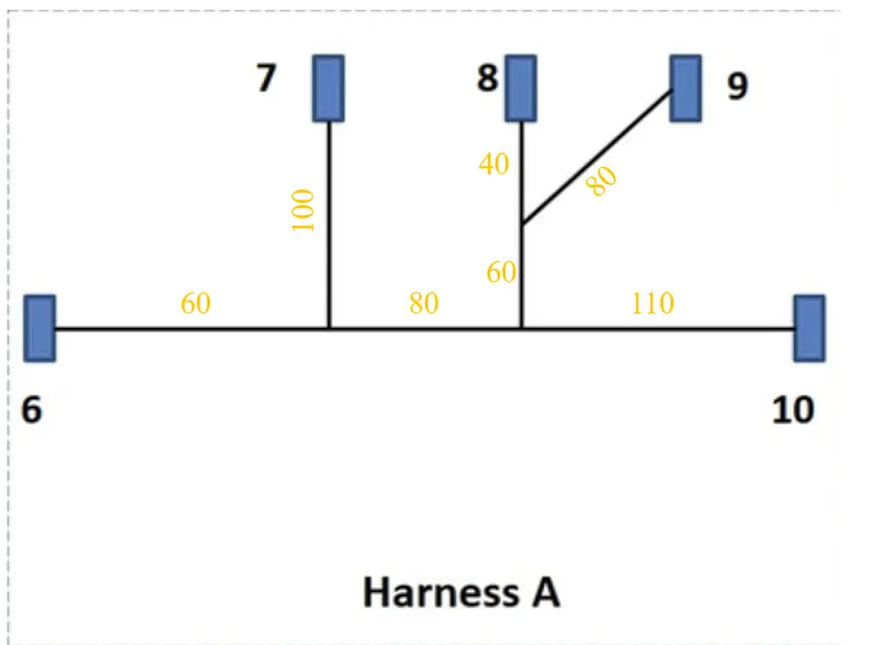
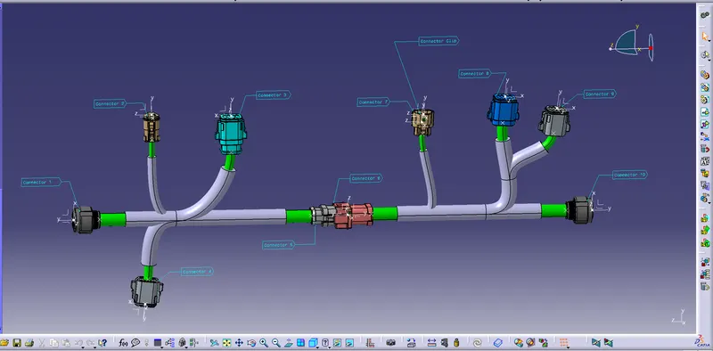
Consider the above wiring diagram with assumed dimensions like length and diameter and download all the Connectors provided. let us assume the length shown in the below fig.
- Define all the connectors as electrically by providing the geometrical elements. Then in the Electrical part design convert the mechanical part to the electrical part by defining the part by giving the Define bundle, Connector connection point and Bundle connection point. Save the part in the catalog.
- Connector 1 & 10
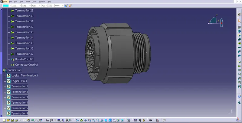
- Connector 2
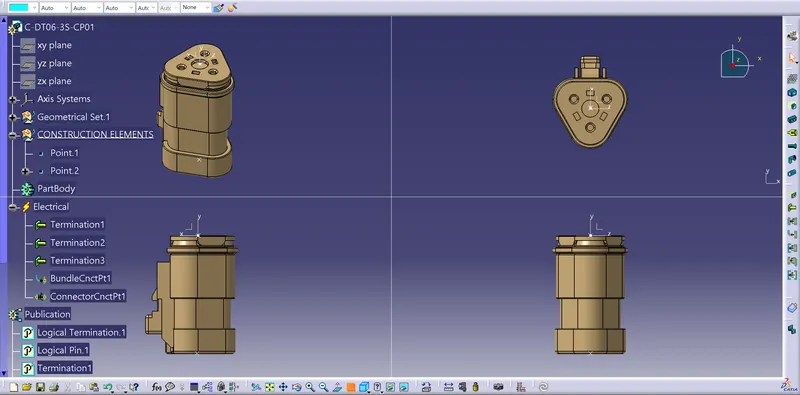
- Connector 3
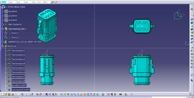
- Connector 4 & 9
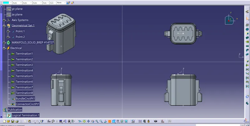
- Connector 5
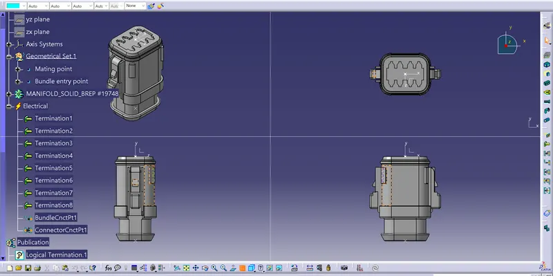
- Connector 6
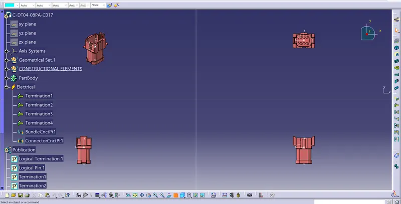
- Connector 7
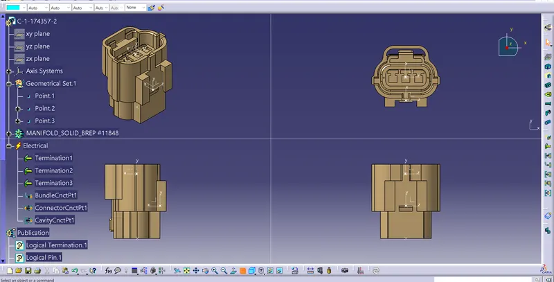
- Connector 8
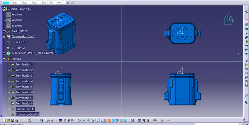
- Connector Clip
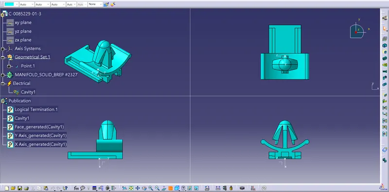
- Next in the Electrical Harness Assembly create the bundle harness btween the connectors of diameters 6 and 10mm diameters and add branch points as shown in the assumed wirring diagram shown in the above fig. Next provide the protection covering with desired diameter.
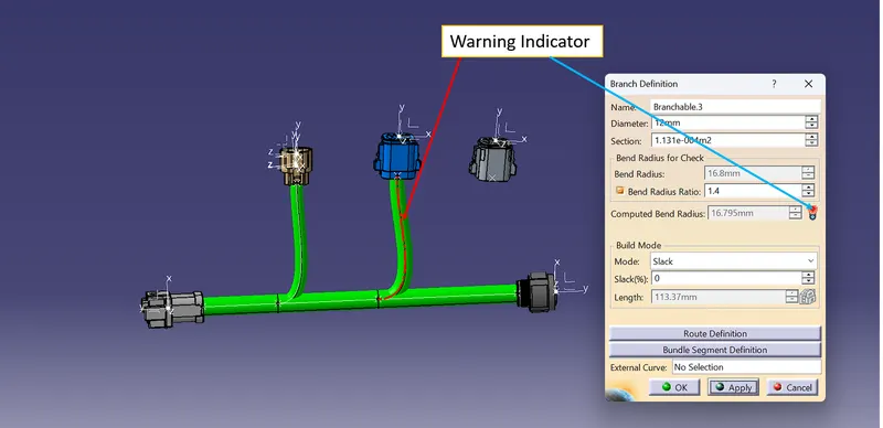
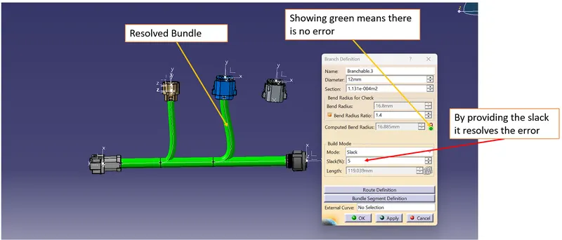
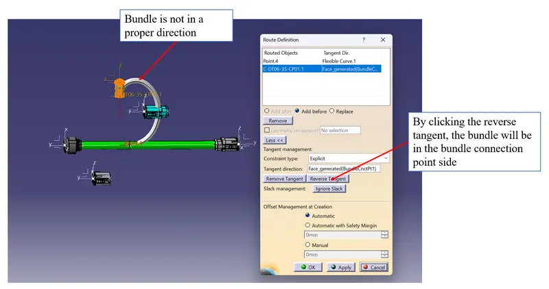
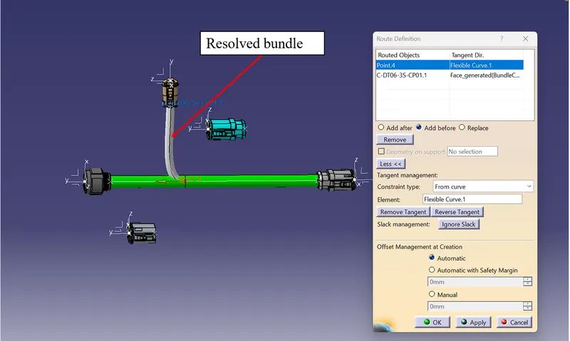
- In some situation crating the bundle in the branched point and connector, it will create error of creation of bundle and it will denoted in the red mark/red light. In this situation there will be number ways to solve the error, by reversing the tangent, by giving some slack to the bundle or by translating the connector by the compass. Some of the examples are shown in the below fig.
- Next is to check the Bundle continuity by the clicking the Edit on the top of the ribbon and click the Search option.
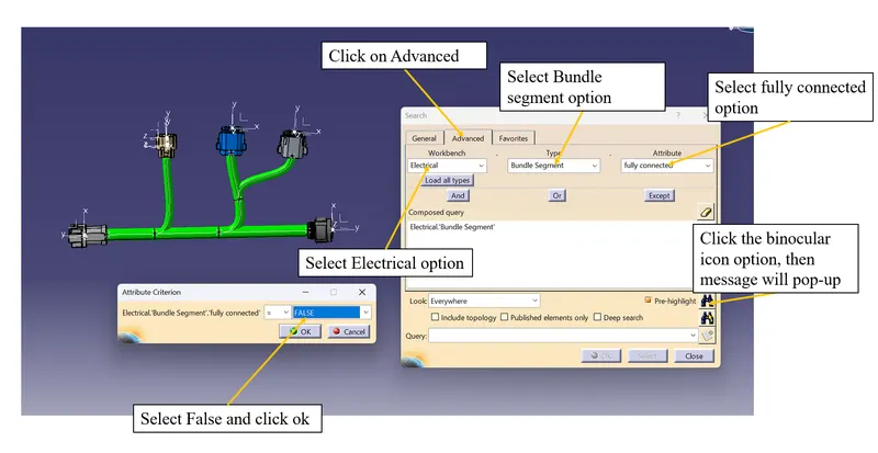
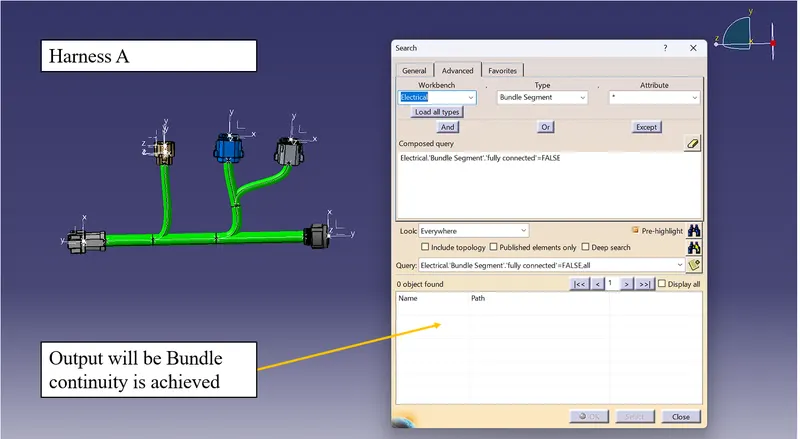
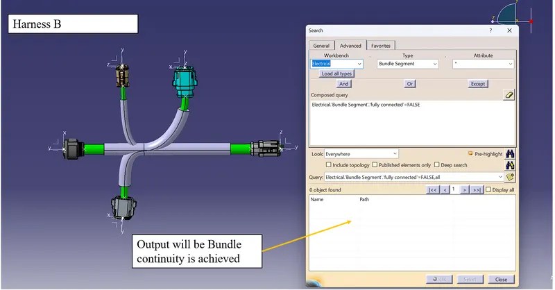
- Finally in the Electrical Assembly Design, using the Connect Electrical Devices tool option to connect the male conncetor from Harness A and female connector from Harness B.
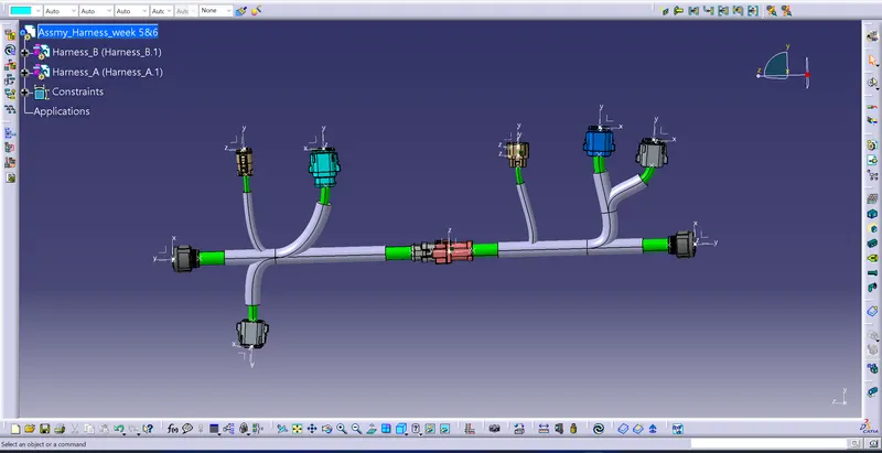
Annotations
- Convert the assembly file to part and save as IGS format file from catproduct to catpart option