Wiring harness design in CATIA V5 - 3D modeling Week 5 & 6 Challenge
- connector
- First I download the cad file in the given question link
- As per the explanation next created required geometrical parameter in the given connector
- What is the geometrical parameter first created the connection entry point --> then the connection axis in the connector-->bundle entry point in the connector --> next define a connector
- Next define parts of the given connector
- Then define bundle connection point and connector connection point as per explanations
- Last we need to define the cavity connection point but this connector does not need that connection point
- Then finally save the changes in the connector to the link path catalog.
Objectives
- I have more than three objectives for this question. My first objective is to draw harness A & Harness B in separate files. the given reverence line using the structure in my Harness A & B.
- My next objective is to two separate harness files gettogether into a single file and connect harness A & Harness B
- Exact explanation is to connect connector 5 and connector 6 in the respective diagram.
- The Third objective is Check the bundle Continuity. Add a snap of the result in a submission
- Next is to Add annotation to all connectors. Make assumptions for annotations like connect 1, 2, etc
- Then Check for the bundle warning. Add a snap of the result in a submission.
- The last thing is Generate CAT.part of harness assembly and convert it in. igs format.
My first objective
- My first objective is to draw harness A & Harness B in separate files. So I already save the connector file into the catalog library. As per the question, the reference structure is taken by our reference.
- So I draw the first reference structure in my catia. therefore I need part work branch in the CATIYA. next, I draw the reference structure in the part file I save Harness B structure is Part 1, and Harness A structure is Part 2 respected file location.
- Then used the catalog library to insert the connector as per the question. The position also gives as per structure.
- next go to the Electrical harness assembly and click the Product file name and click the geometrical bundle tool--->next generated a multibranchable document as per the question --->next create the breaking point in the bundle segments as per the question---> create branch bundle segment as per the question----->save file
My second objective
- My next objective is to two separate harness files gettogether into a single file and connect harness A & Harness B
- So first I created a new product---> copy file harness A & Harness B and paste it into the new product ---->next go to the electrical Assembly design work branch -----> use the tool to Connect Electrical Device and connect harness A & Harness B as per the question----->save the file
My Third objective
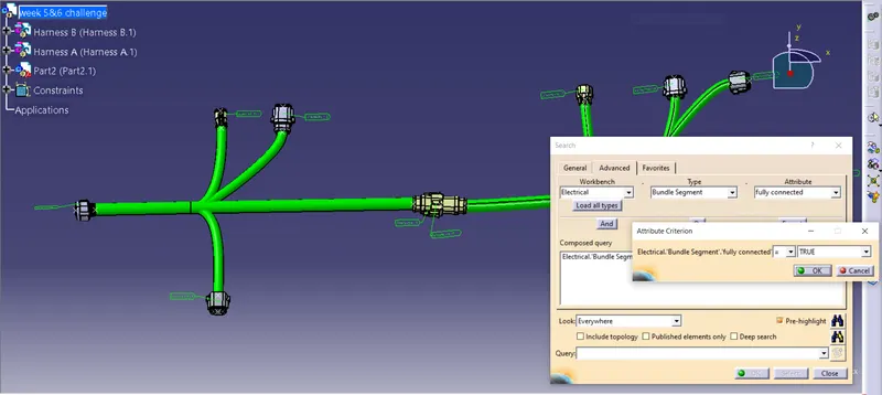
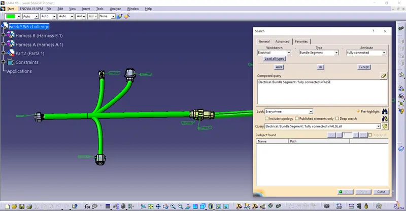
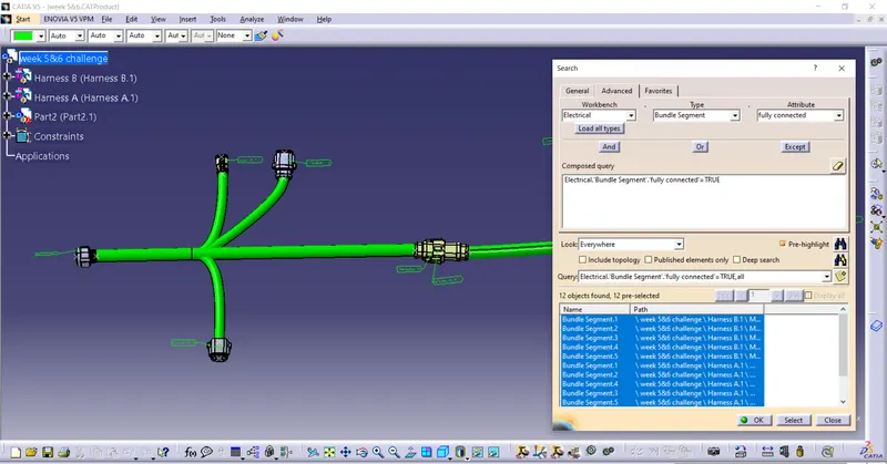
- The Third objective is Check the bundle Continuity. Add a snap of the result in a submission.
- AS per the question I check the bundle continuity in the new product results below there.
My fourth objective
- Next is to Add annotation to all connectors. Make assumptions for annotations like connect 1, 2, etc
- It is done as per the question
My fifth objective
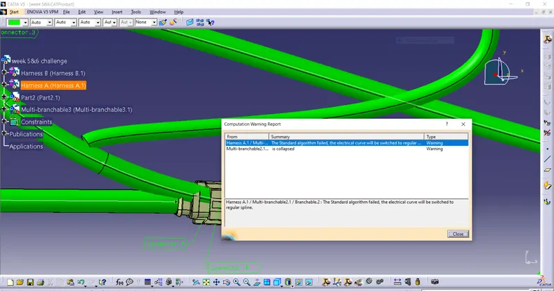
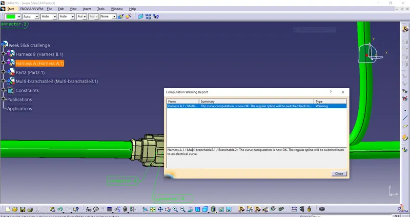
- Then Check for the bundle warning. Add a snap of the result in a submission.
- As per the question check the bundle warning and resolve the problem result below there
My Lost objective
- The last thing is Generate CAT.part of harness assembly and convert it in. igs format.
- It is also done as per the question