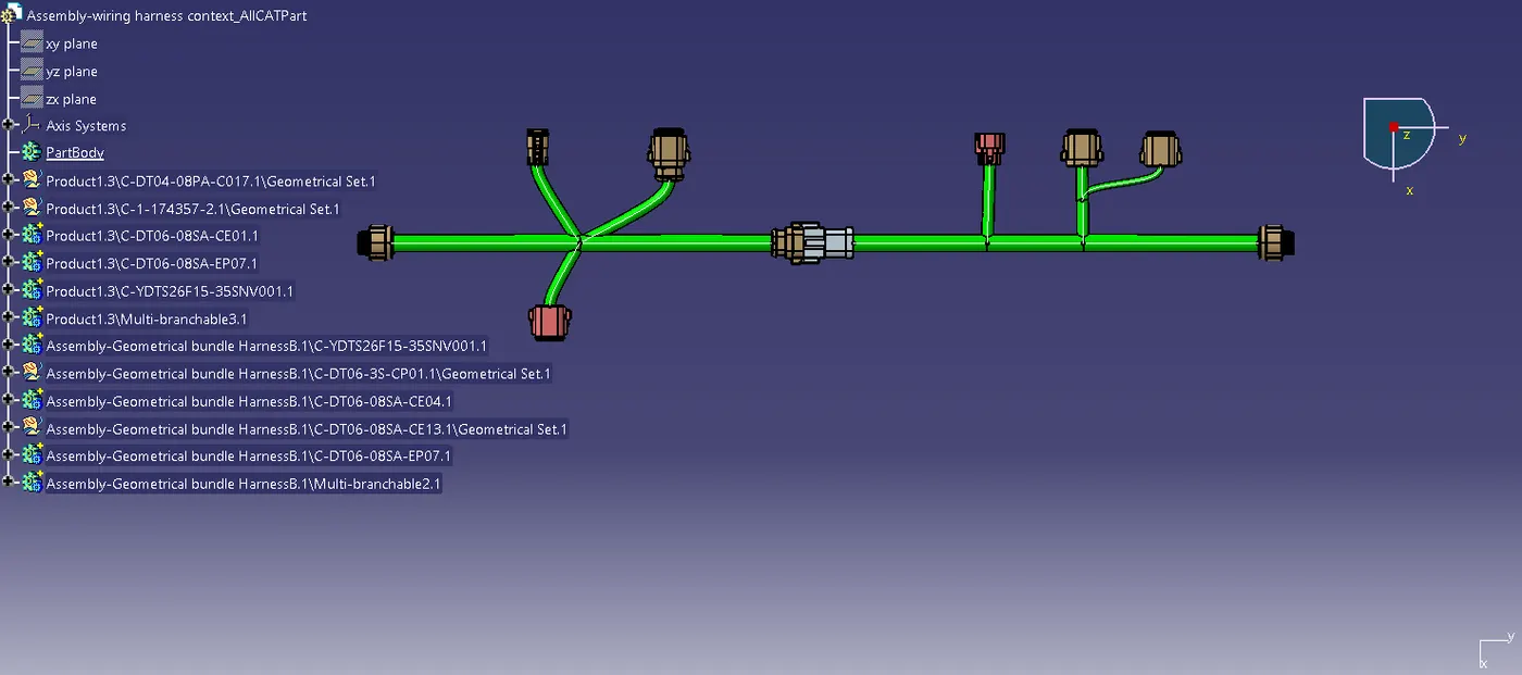
Wiring harness design in CATIA V5 - 3D modeling Week 5 & 6 Challenge
HARNESS B:
Manifold 1:
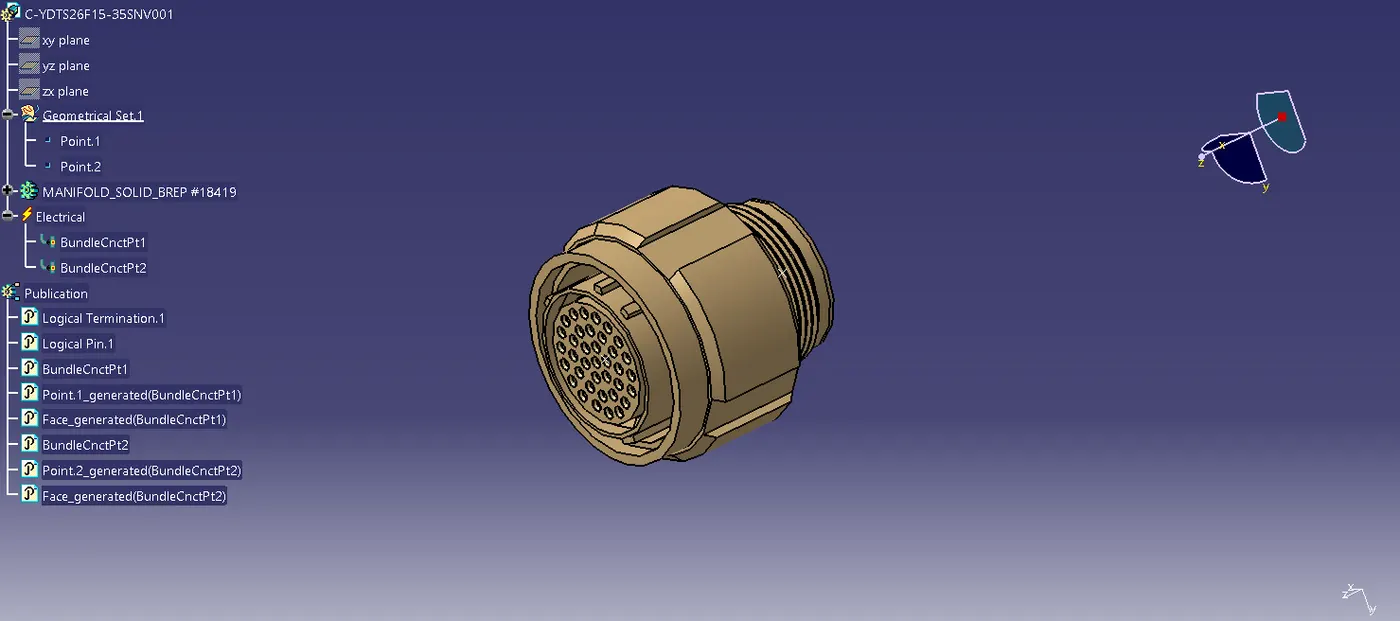
This manifold housing is defined as a mounting equipment using electrical part design workbench. Points are created at both ends. Then Bundle connnection points and catalogues for the connector also created.
Connector 2 :
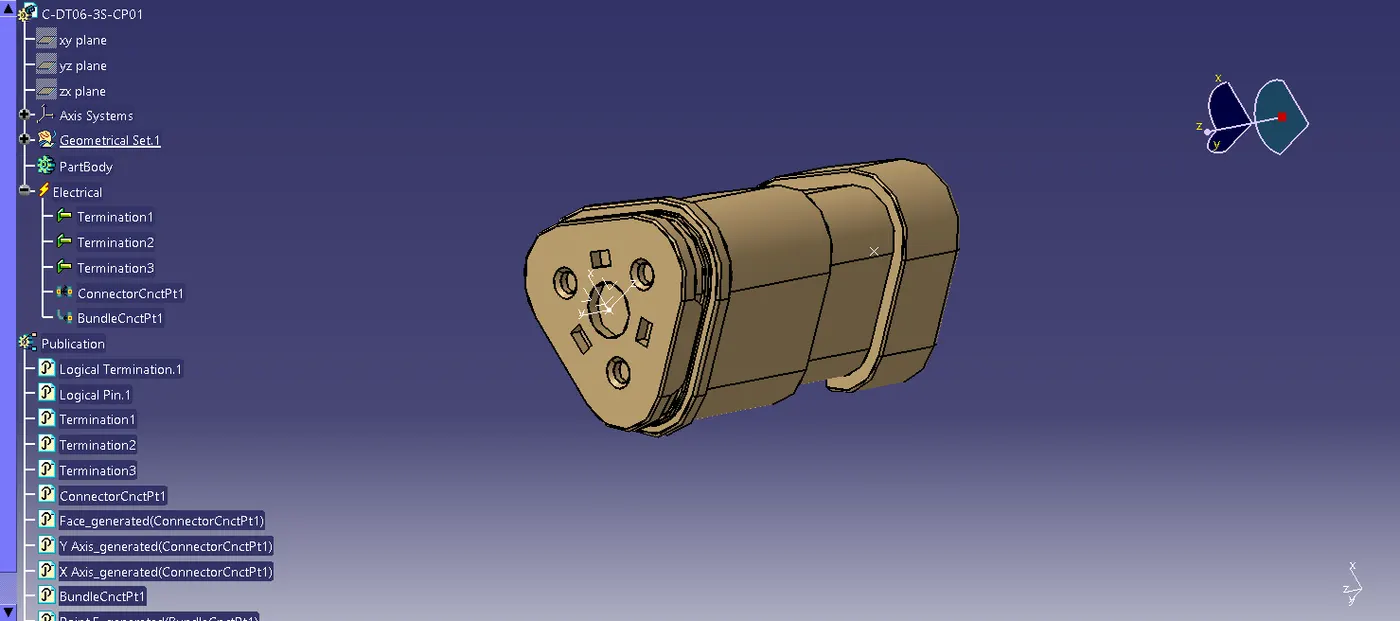
This connector housing consists of 3 terminals, it is defined as an electrical connector using electrical part design workbench. The axis system is created at the mating part of the connector, where the X,Y,Z axis are placed at the direction of the locking mechanism of the chip, mating front face of the connector and in the point across the connector from left to right respectively. Then the Connector connection point ,Bundle connnection point and catalogues for the connector also created.
Connector 3 :
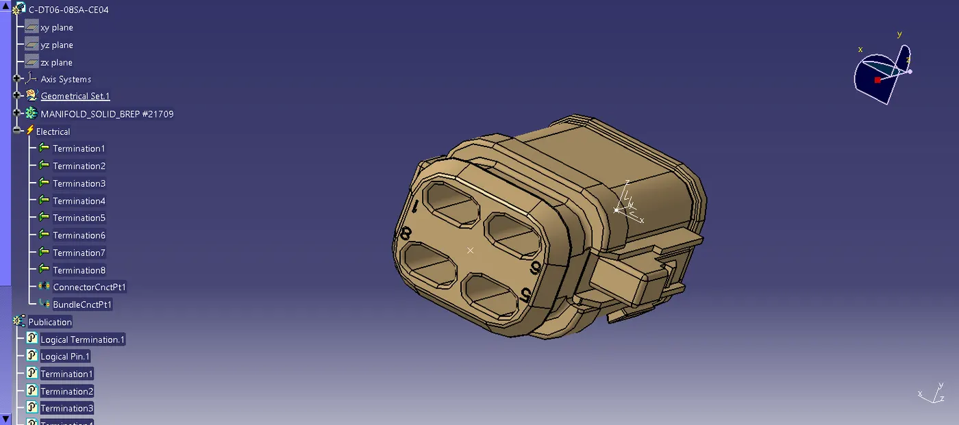
This connector housing consists of 8 terminals, it is defined as an electrical connector using electrical part design workbench. The axis system is created at the mating part of the connector, where the X,Y,Z axis are placed at the direction of the locking mechanism of the chip, mating front face of the connector and in the point across the connector from left to right respectively. Then the Connector connection point ,Bundle connnection point and catalogues for the connector also created.
Connector 4 :
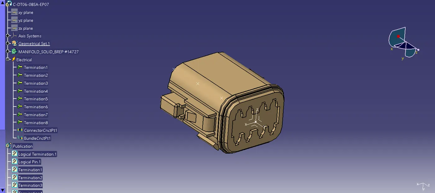
This connector housing consists of 8 terminals, it is defined as an electrical connector using electrical part design workbench. The axis system is created at the mating part of the connector, where the X,Y,Z axis are placed at the direction of the locking mechanism of the chip, mating front face of the connector and in the point across the connector from left to right respectively. Then the Connector connection point ,Bundle connnection point and catalogues for the connector also created.
Connector 5 :
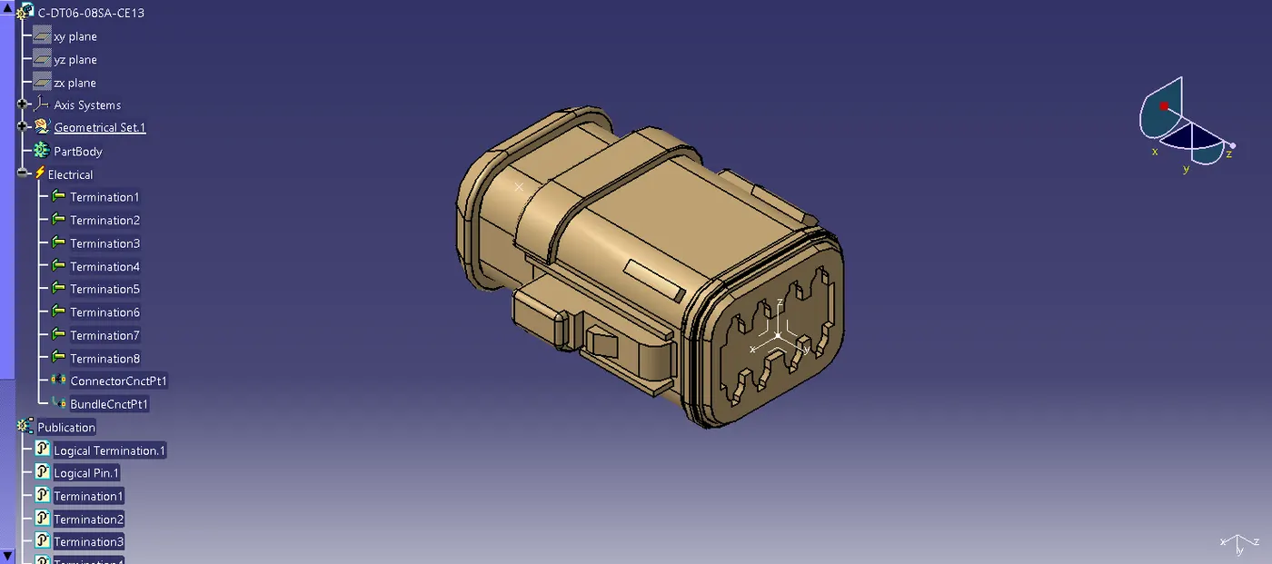
This connector housing consists of 8 terminals, it is defined as an electrical connector using electrical part design workbench. The axis system is created at the mating part of the connector, where the X,Y,Z axis are placed at the direction of the locking mechanism of the chip, mating front face of the connector and in the point across the connector from left to right respectively. Then the Connector connection point ,Bundle connnection point and catalogues for the connector also created.
Connector 6:
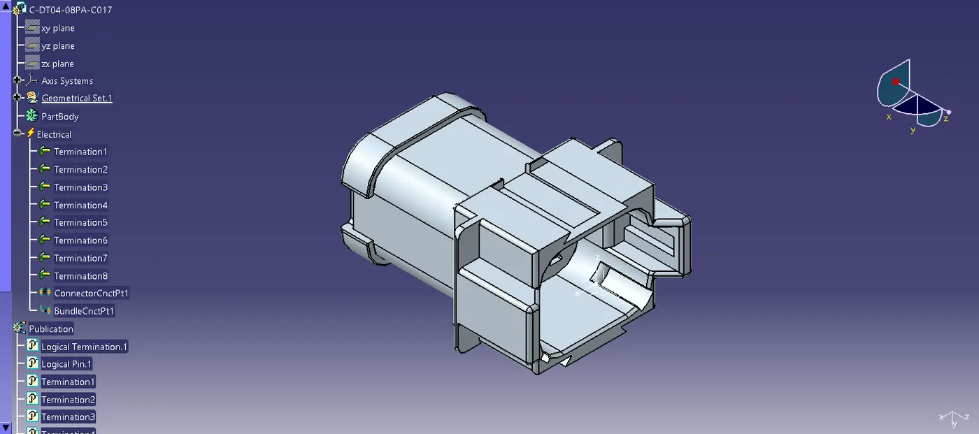
This connector housing consists of 8 terminals, it is defined as an electrical connector using electrical part design workbench. The axis system is created at the mating part of the connector, where the X,Y,Z axis are placed at the direction of the locking mechanism of the chip, mating front face of the connector and in the point across the connector from left to right respectively. Then the Connector connection point ,Bundle connnection point and catalogues for the connector also created.
Connector 7:
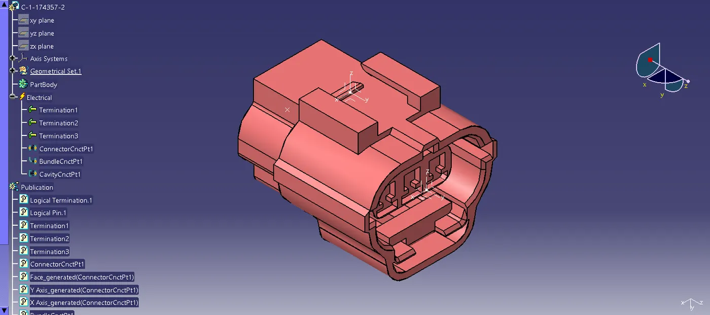
This connector housing consists of 3 terminals, it is defined as an electrical connector using electrical part design workbench. The axis system is created at the mating part of the connector, where the X,Y,Z axis are placed at the direction of the locking mechanism of the chip, mating front face of the connector and in the point across the connector from left to right respectively. Then the Connector connection point ,Bundle connnection point and catalogues for the connector also created.
Connector 8:
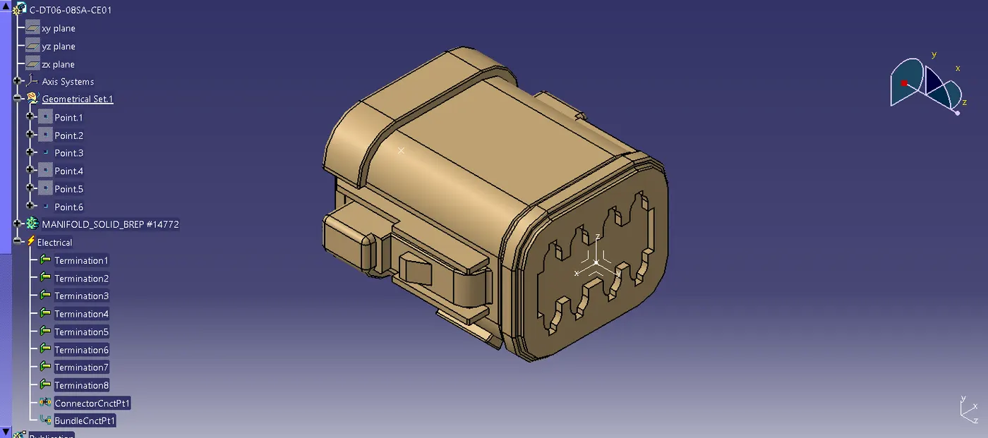
This connector housing consists of 8 terminals, it is defined as an electrical connector using electrical part design workbench. The axis system is created at the mating part of the connector, where the X,Y,Z axis are placed at the direction of the locking mechanism of the chip, mating front face of the connector and in the point across the connector from left to right respectively. Then the Connector connection point ,Bundle connnection point and catalogues for the connector also created.
Connector 9 :
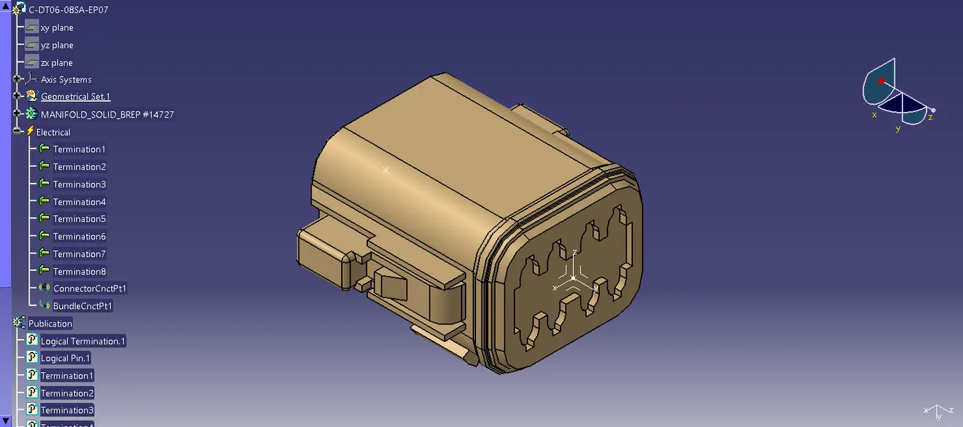
This connector housing consists of 8 terminals, it is defined as an electrical connector using electrical part design workbench. The axis system is created at the mating part of the connector, where the X,Y,Z axis are placed at the direction of the locking mechanism of the chip, mating front face of the connector and in the point across the connector from left to right respectively. Then the Connector connection point ,Bundle connnection point and catalogues for the connector also created.
Manifold 10:
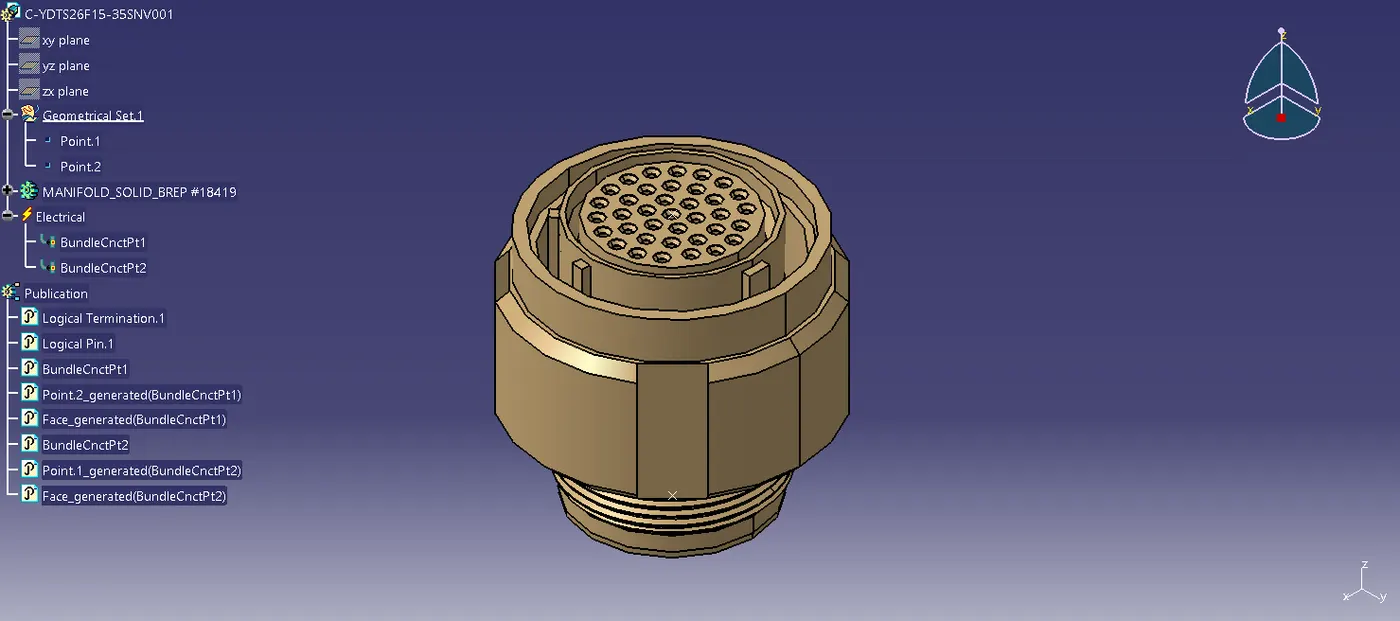
This manifold housing is defined as a mounting equipment using electrical part design workbench. Points are created at both ends. Then Bundle connnection points and catalogues for the connector also created.
BUNDLE CONTINUITY:
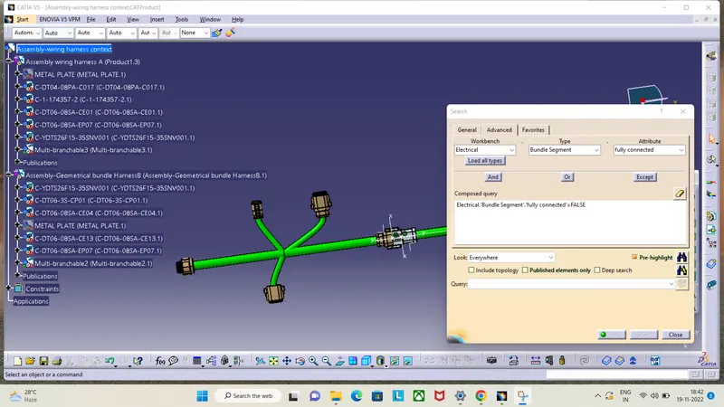
For Bundle continuity check, Edit< search<Advanced<workbench(electrical)<type(bundle segment)<Atribute(fully connected)
ANNOTATION:
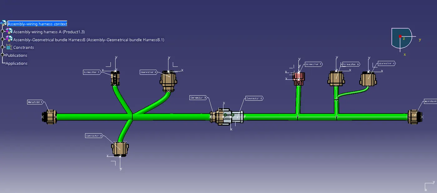
HARNESS INTERCONNECTION:
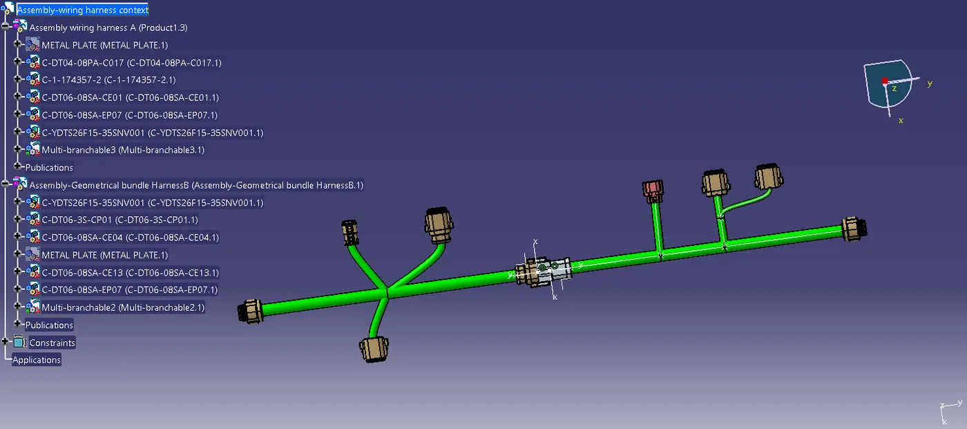
It is done by Electrical assembly design. Where both harness A and harness B are interconnected using connectors.
CAT part conversion: