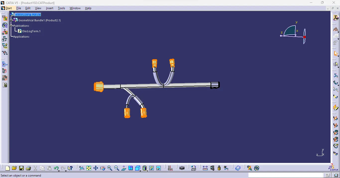
Wiring harness design in CATIA V5 - 3D modeling Week 4 Challenge
REPORT
First step is to download the CAD files from the source, after that define each of them as an Electrical Part.
Defining the Electric part as follows,
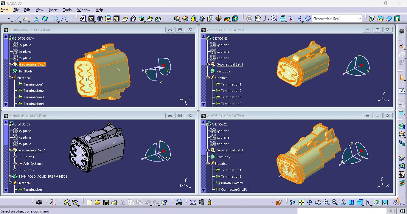
Open the connector cad part
At first a point has been created on the mounting side of connector. Next Create an Axis system by taking the created point as origin.
While Creating axis system few rules are to be followed on the setting of the orientation of axis.
X-Axis should be towards the locking mechanism.
Y-Axis should be towards mounting direction.
After that we need to define the cavity connection point. On the connector a locking feature is been provided. Create a point on the edge of locking feature. Now create an axis system by taking the created point as origin. Orientation of axis on the axis system should be followed as same as done in mounting side.
Now Switch to Electrical Part Design
Define the connector by Define connector option. Provide type as Single Insert Connector and provide the number of terminations. Now select Bundle connection point option and define the bundle connection point. Select face as representation and on initial condition select the same face.
Now select Connector connection point for creating the connection point. Click on connector, Select the point created on connection point as representation and on contact select the face on which point created. Coincidence select X-Axis and orientation select Y-Axis.
Follow the same steps for other connector also.
Now the next step is routing.
For that we need to assemble all electrically define connectors.
First create a Product file by FileàNewàProduct.
Now add new product by right click on productàcomponentsànew product. In that right click and select existing components under component and add the file. After that define it as geometric bundle. Now by manipulation and snap tools making proper orientations on connector as needed.
After that click on Multi Branch-able Document option and Give diameter and bend ratio as 1.4 then click on Route definition and select the connectors click on ok. These steps are followed for other connectors.
Now Add protective coverings, select the Protective covering option and select the required diameter covering from catalogue and click on the tube where needed provide end extremity as required.