Wiring harness design in CATIA V5 - 3D modeling Week 4 Challenge
1.
Connector Definition:
- Firrst download the required connectors such as DT06-6S, DT06-4S, DT06-2S and DT06-08SA from www.te.com
- Then define the connectors as electrical paart from mechanical part by giving Connector Axis, connection point and Bundle Connection point
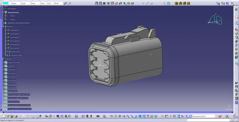
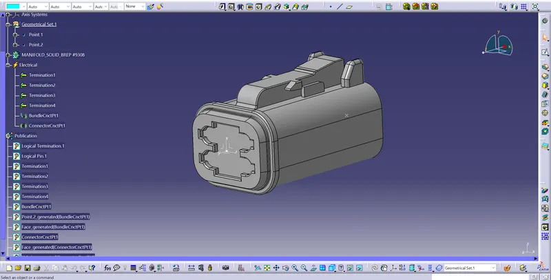
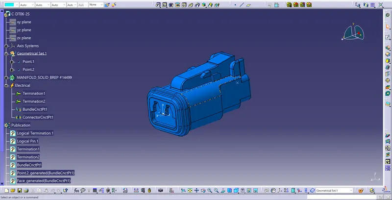
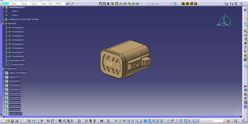
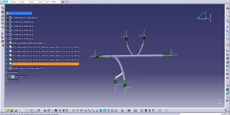
- Next create the product file for the assembly and harness the bundles for the connectors as shown in the figure below
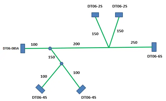
- As shown in the above fig pllace the connectors in the respective position using Compass or Manipulation for translation and rotation.
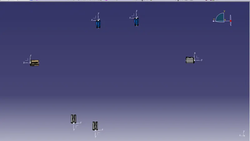
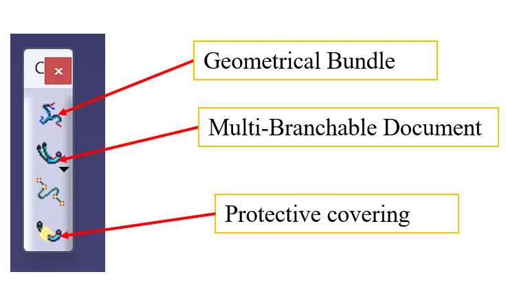
- In the Eelectric Harness Assembly use the Geometric Bundle tool to deifne the product as Electical(we can see the change in the product logo)
- Using the Multi-Branchable Document Create Bundle between the connectors with proper dimensions.
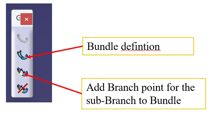
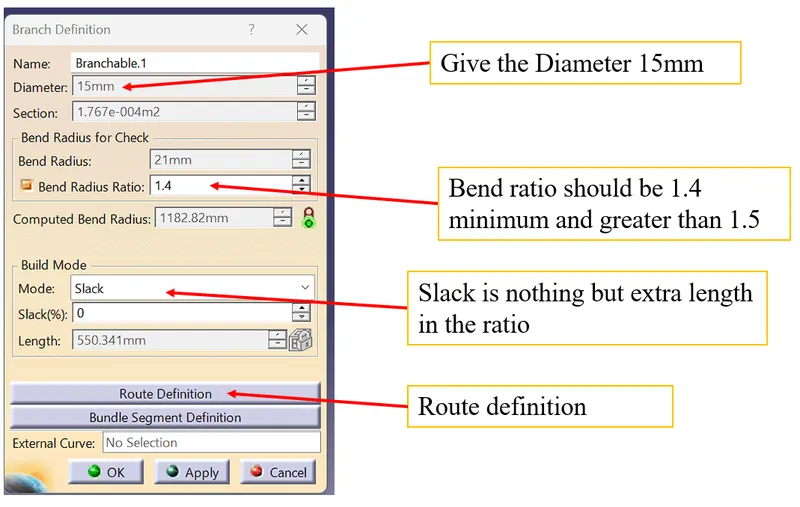
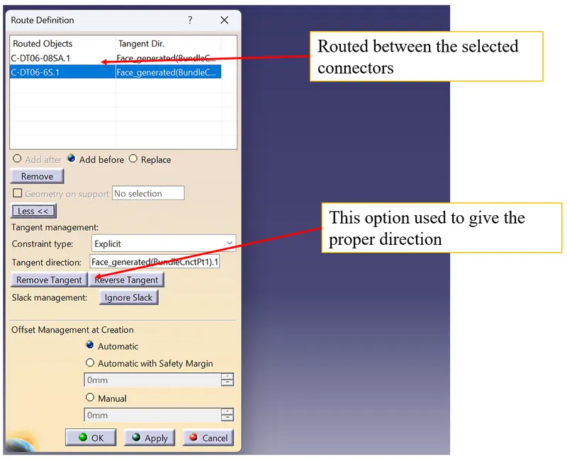
- Click ok and ok, the bundles are applied
- Do the same for other connectors using the diameter as 15mm and 6mm.
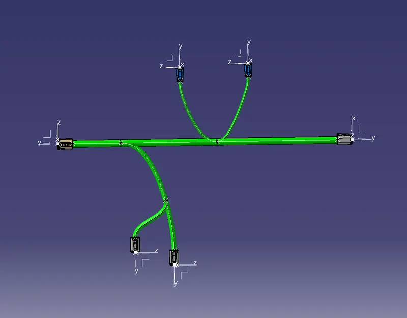
- Add the protective covering to the bundles Keep end extremity at 30mm from the connectors end with the appropriate diameters.
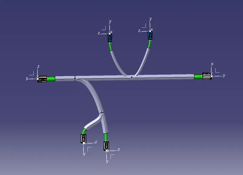
- Save the file using file mangenent