Wiring harness design in CATIA V5 - 3D modeling Week 2 Challenge
Week 2 Challenge Report
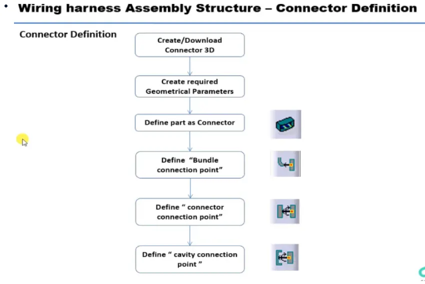
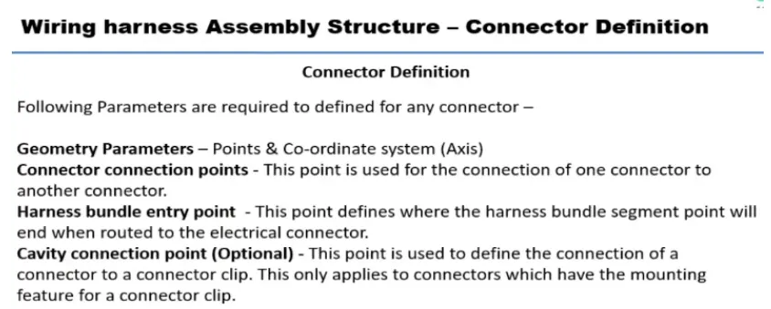
Connector definitions in catia V5
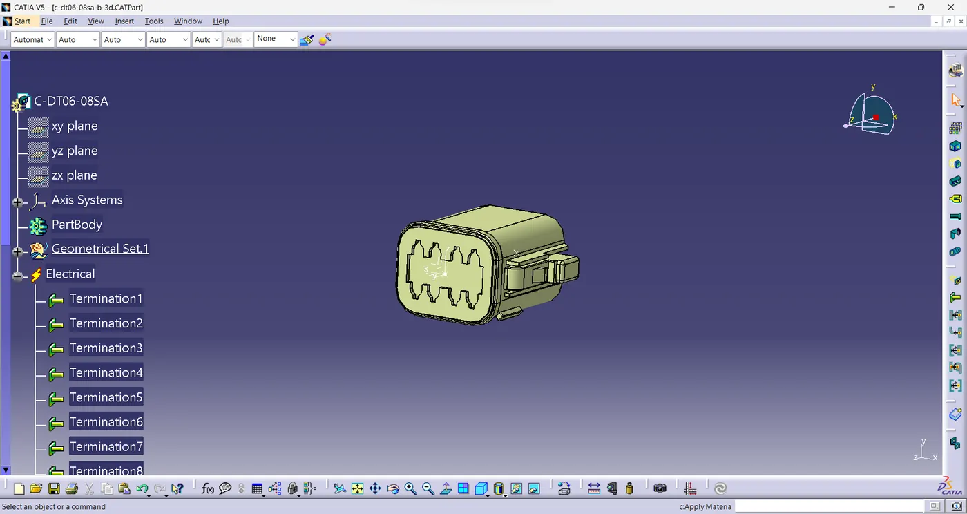
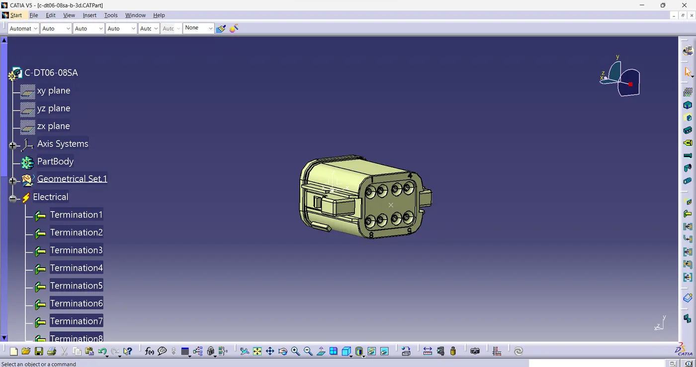
1.Deutsch DT06-08SA
Create geometrical parameters.
1. Open Mechanical part design workbench
2. Find the bundle connection side.
3. Create a mid-point for the bundle connection point.
4. Find the connection point.
5. Create a mid-point for the connector connection point.
6. Create an axis on the point where,
Y axis-towards front
X axis-towards the locking mechanism
Z axis- left to right
7. Switch to electrical part design.
8. Define the part as connector.
9. Provide the no of termination as 8since we have 8 points for wire.
10. Define bundle connection point.
11. Define connector connection point.
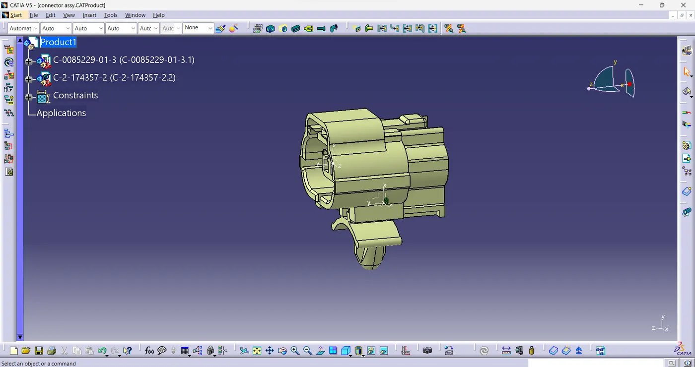
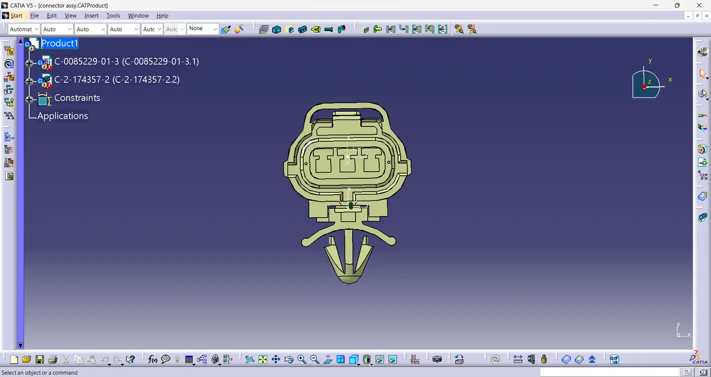
2.Tyco 174357-2:
Create geometrical parameters.
1. Create midpoint for bundle connection.
2. create Connector connection point.
3. create Connector connection axis system.
4. create cavity connection point.
5. create cavity connection axis system.
Switch to Electric part design and define part as connector.
Define Connector connection point and cavity connection point and bundle connection point.
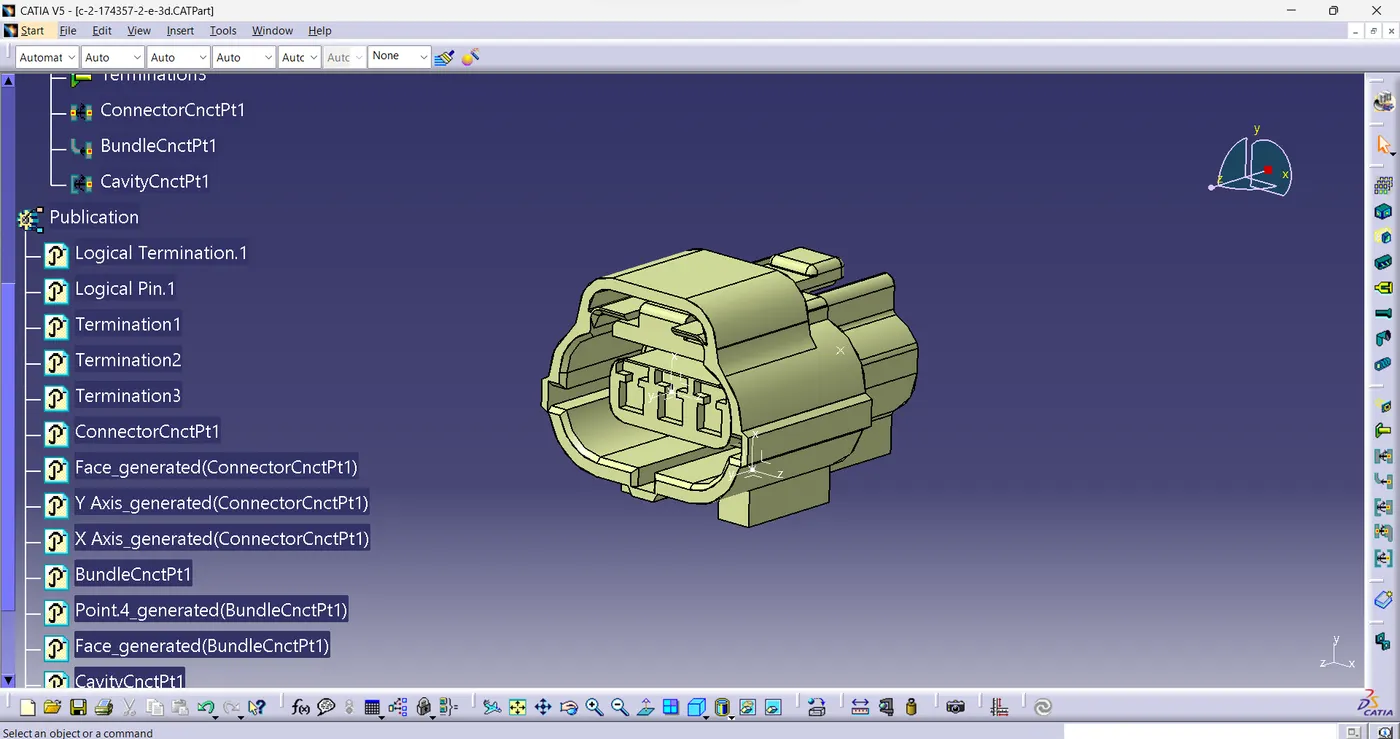
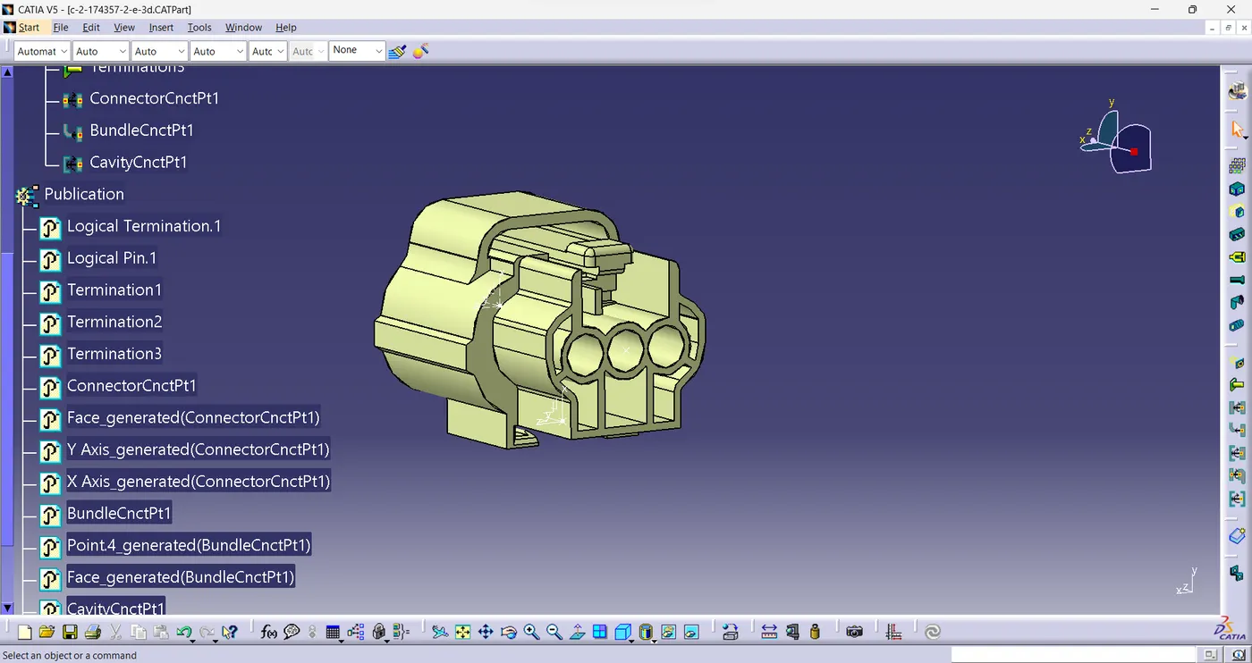
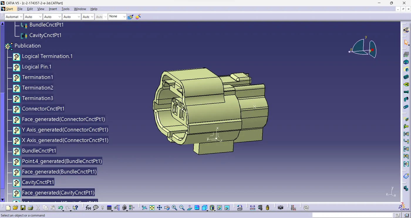
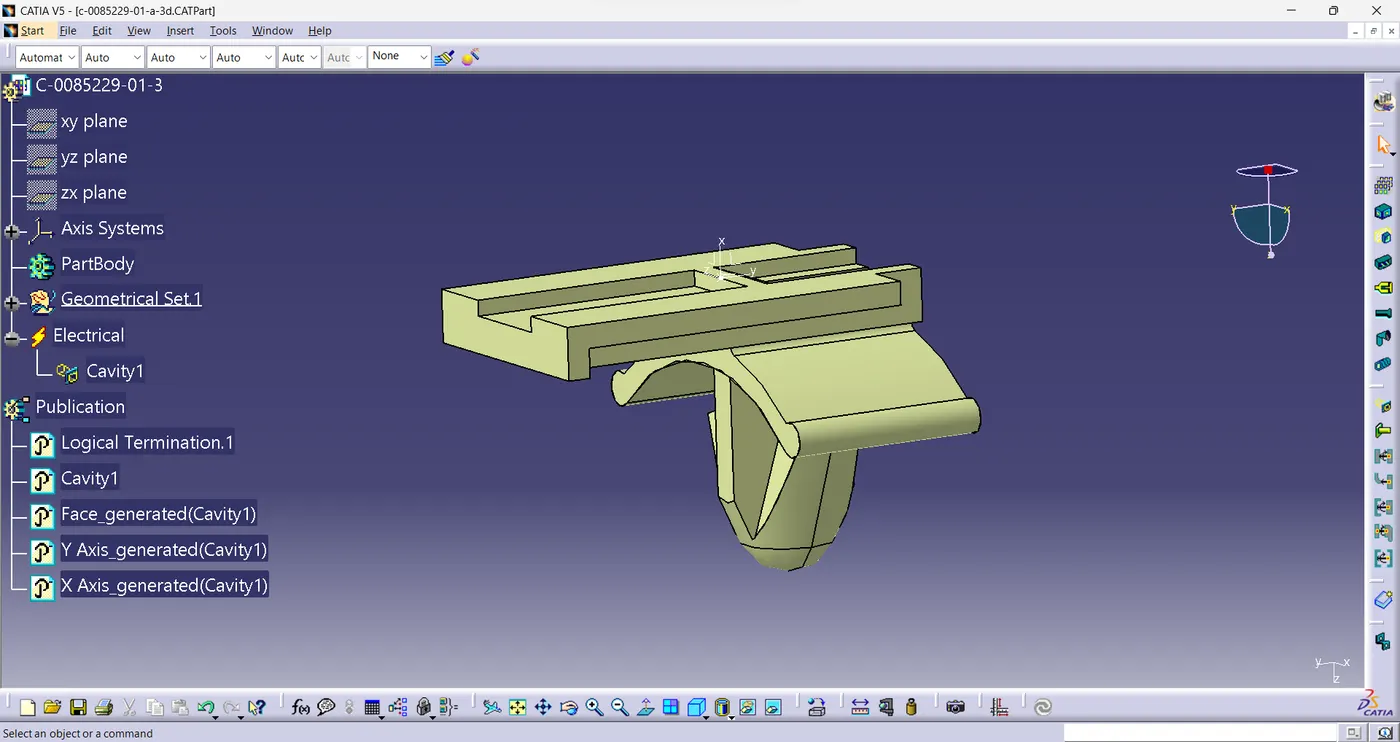
3.Tyco 85229-1:
Create geometrical parameters.
1. Create midpoint.
2. create cavity connection point.
3. create cavity connection axis system and orientation should be same as in connector.
4. Switch to Electric part design and define part as Mounting Equipment
5. Define cavity connection point.
Electrical Assembly Design
1. Import Connector and cavity / mounting clip.
2. Select Defining Electrical connection.
3. select cavity and then connector.
x-------------------------x