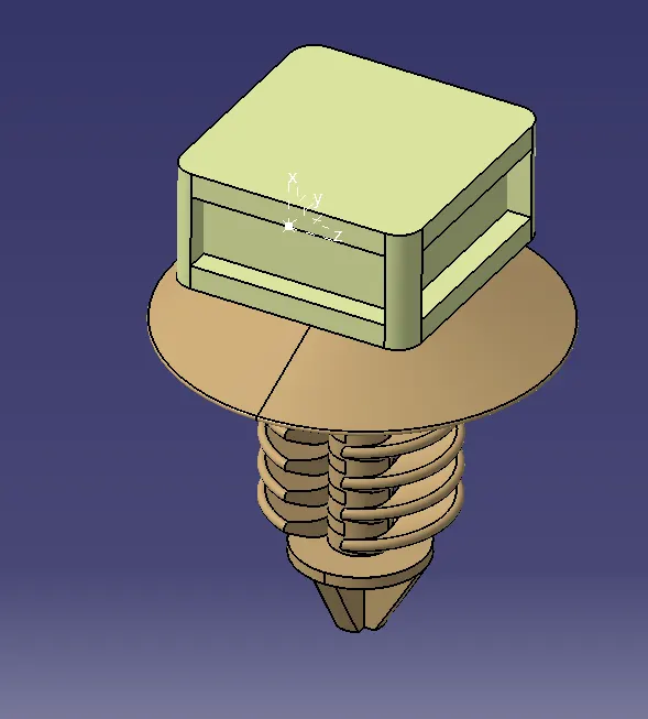
Wiring harness design in CATIA V5 - 3D modeling Week 2 Challenge
AIM - Downloading connectors & Connector clip cad data & define it as Electrical Connector using Electrical Part design Workbench. Define all the necessary properties to Connectors & Clip.
HARNESS DESIGN PROCESS – Using Physical Architecture, Harness routing and packaging is designed.
STEP 1 - Identify the harness assembly components
STEP 2 - define all harness components as electrical
STEP 3 - prepare harness assembly
STEP 4 - define assembly as electrical assembly
STEP 5 – change tool setting as required
STEP 6 – start routing the bundles
WIRING HARNESS ASSEMBLY STRUCTURE –
CONNECTOR DEFINITION –
STEP 1 – Create / download connector 3D
STEP 2 – Create required geometrical parameters
STEP 3 – Define part as connector
From electrical part workbench select part as a connector, which states part functions as electrical component.
STEP 4 – define Bundle connection point
Create a point on the wire entry side with reference as face normal to the bundle connection point
This point defines where the harness bundle segment point will end when routed to the electrical connector.
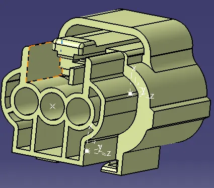
STEP 5 - define connector connection point
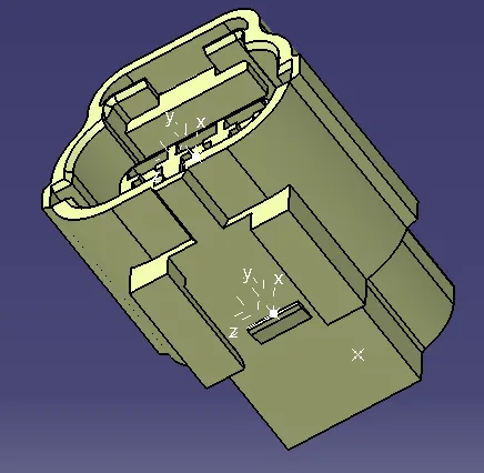
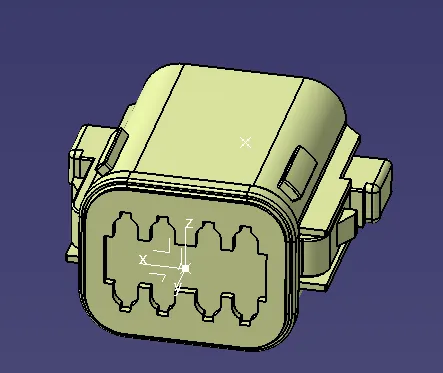
Geometry parameters – create a point on the face of the mating side and create a coordinate system at a point created with Y-AXIS should be pointing towards the front face of the connector, same direction as the harness to the connector, X-AXIS should be pointing in the direction towards the locking mechanism of the clip and Z-AXIS should be pointing across the connector from left to right. Can use your own but it should be consistent for mating connectors.
Connector connection point – this point is used for the connection of one connector to another connector.
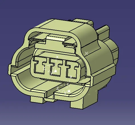
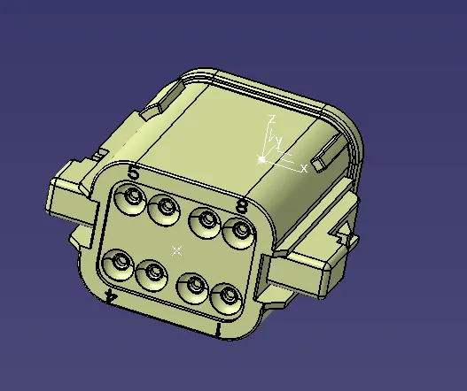
STEP 6 – define cavity connection point
The point is used to define the connection of a connector to a connector clip. This only applies to connectors which have the mounting feature for a connector clip.
MOUNTING CLIP DEFINITION –
STEP 1 – Create / download connector 3D
STEP 2 – Create required geometrical parameters
STEP 3 – Define part as mounting
From electrical part workbench select part as a mounting, which states part functions as electrical component.
STEP 4 - define mounting clip connection point
create a point on the face of the mating side and create a coordinate system at a point created with Y-AXIS should be pointing towards the front face of the connector, same direction as the harness to the connector, X-AXIS should be pointing in the direction towards the locking mechanism of the clip and Z-AXIS should be pointing across the connector from left to right.
The point and axis should be consistent with the component it is mating with.