Wiring harness design in CATIA V5 - 3D modeling Week 2 Challenge
AIM
To download the connector and connector pin and define it as electrical parts using catia software.
INTRODUCTION
we have given three link to download the cad file.on which two of them are female connector and rest is a connector clip.
PROCEDURE
Download the cad file from the given link.
In part design work bench; create point and axis coordinates to make them constrain in electrical part design work bench.
To define these as electrical component;give equipment details like connector and cavity details in electrical part design work bench.
THEORY
To make the points and axis coordinates;we do that in part design work bench.
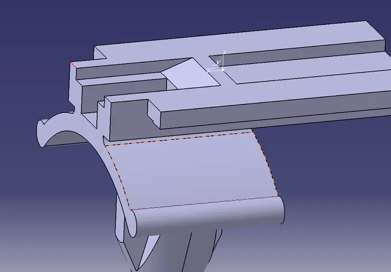
The above picture is the connector pin.here we have given a point in the middle of the edge and an axis coordinates as shown.the point is given on that edge which will coinside with the connector during coinside. and the axis system is in the same orientation as the axis system in the axis coordinates in the cavity region of the connector.
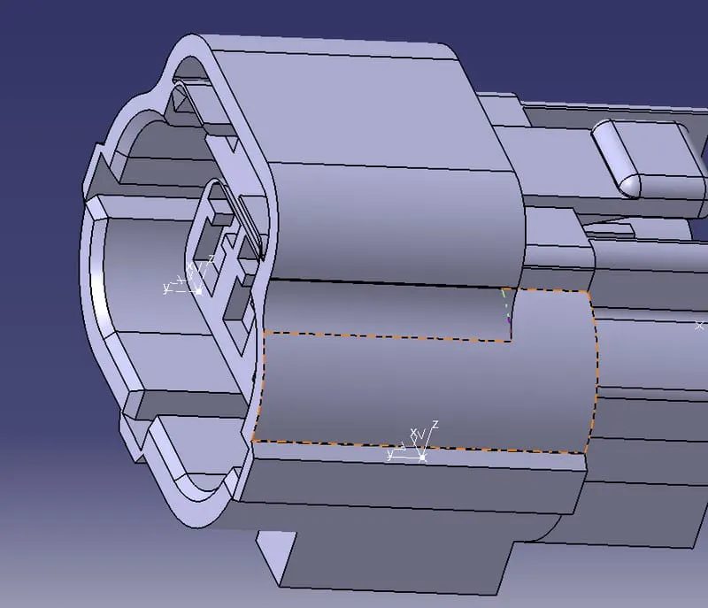
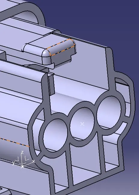
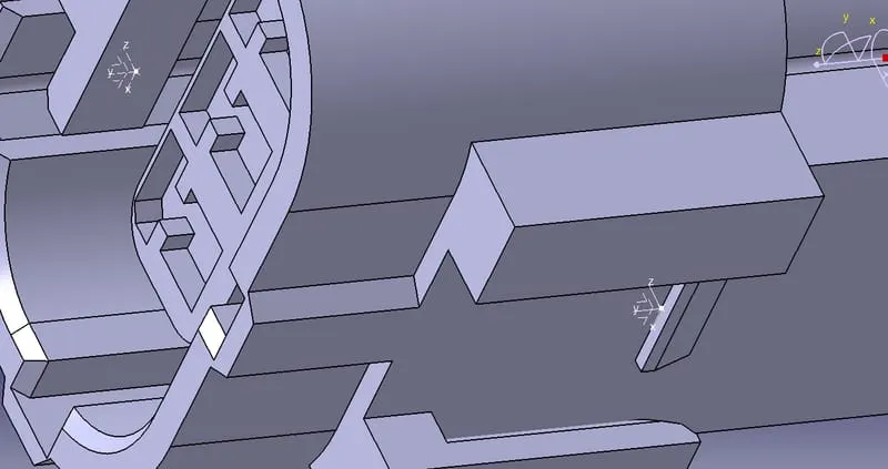
This shows point and axis coordinates marked on one of the connector.here in this connector we have a cavity region to attach the connector clip.connector has mating region and bundle region.in mating region;mating with the male connector happens.in bundle region;wires would joint as bundles as accoridng to number of poles.
The left image shown is the mating region.an axis coordinates are given by taking middle point of the mating surface area as origin.the y axis is facing in same direction as mating direction.x and z axis is facing to the side of the connector.by this same manner other connector is made.
The middle image shows the bundle region where wires come.here 3 poles or terminals are there.a pont is drawn in the middle of the bundle region facing area as shown.
The third image shows the cavity region to attach the connector clip to make it stiff.the point drawin is in the middle of the edge visible.and the axis coordinates are in same orientaion as that of in mating region.
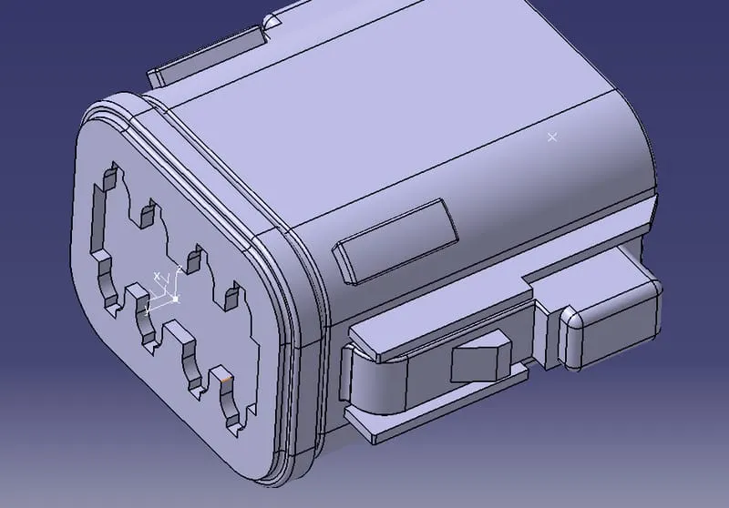
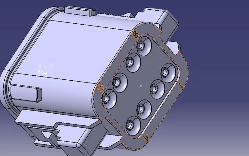
This image is the other of the female connector with no cavity region to attach connector pin.here e have 8 poles or terminals in bundle region.the point and axis coordinates are drawn same like the above connector in the mating and bundle region.
We define the cad part to electrical part in electrical part design work bench.for connector; first we define it as connector by selcting the object after selecting this option
Also we mention number of poles or terminals it have.next we give connector details like representation,orientation etc by clicking this option
for bundle connection details we select this option
if the connector have clip or cavity region; we gave it's details too by selecting this option
for defining connector clips; we select this option

we gave neccessary details here to define cavity connection region.
after giving all details; we can assemble them in electrical assembly work bench by secting connect equipment option.we can save them as catlog and use them in future.this helps to save time and effort.
we can save them by using this option
RESULT
We have defined the 3d models into electrical parts by giving neccessary details in electrical part design work bench.