Wiring harness design in CATIA V5 - 3D modeling Week 2 Challenge
ELECTRICAL DISTRIBUTION SYSTEM
Electrical Distribution System (EDS) refers to the network of components and subsystems designed to distribute electrical power and signals throughout a vehicle or machinery. It plays a critical role in ensuring the proper functioning of various electrical and electronic systems.
Applications of EDS:
· Automotive (wiring harnesses in cars, trucks, and EVs).
· Aerospace (power and signal distribution in aircraft).
· Industrial machinery (control and monitoring systems).
CONNECTOR DEFINITION:
1. Create the Connector Geometry:
o Open the Part Design workbench.
o Design the connector geometry:
§ Include features such as pinholes (for electrical contacts) and a bundle entry point.
2. Switch to Electrical Part Design:
o Go to Start > Equipment & Systems > Electrical Part Design.
o Open the connector part created in the Part Design workbench.
3. Define the Connector:
o Select Define Connector from the toolbar.
o Click on the part to designate it as an electrical connector.
4. Define the Bundle Connection Point:
o Select Bundle Connection Point from the toolbar.
o Choose a face or surface where the bundle will connect.
o Adjust the direction arrow to match the routing direction of the harness.
5. Define the Connector connection point:
o Select Add Contact Point from the toolbar.
o Click on the pinhole or surface where the wire will connect.
o Define the orientation and location for each pin.
o Repeat for all pins.
6. Define the Cavity Connection Point( if there is a connector clip):
- Position: Define the position of the cavity
- Orientation: Set the orientation of the cavity, usually aligning it with the axis of the connector or pin.
7. Save the Connector:
o Save the connector part with its electrical properties for use in harness assemblies.
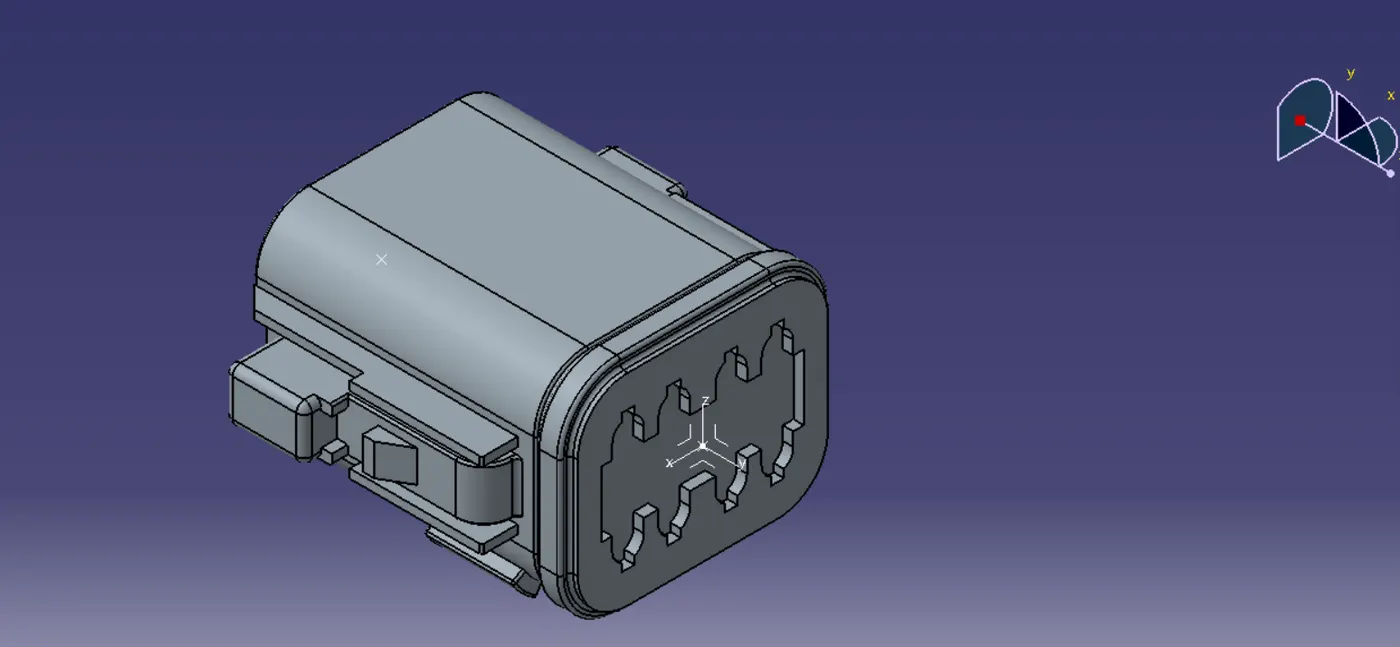
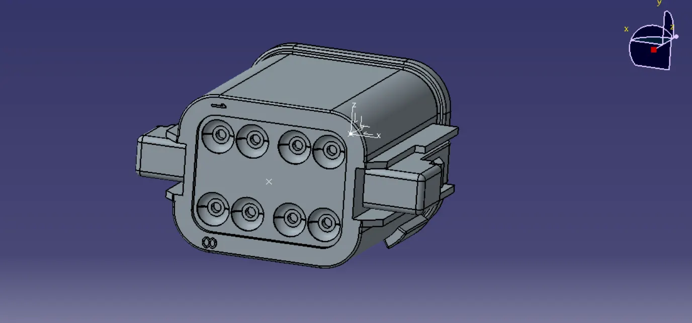
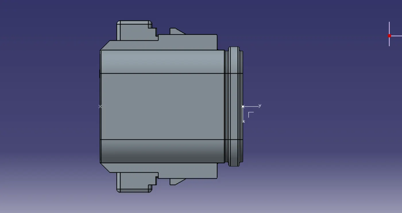
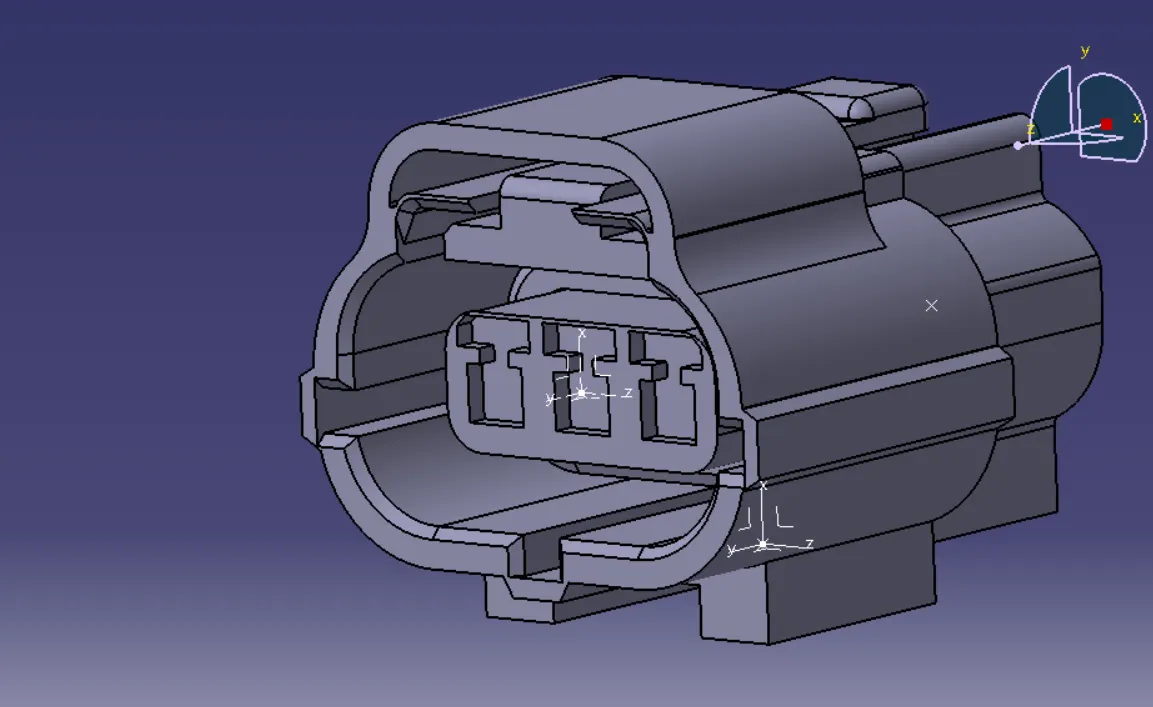
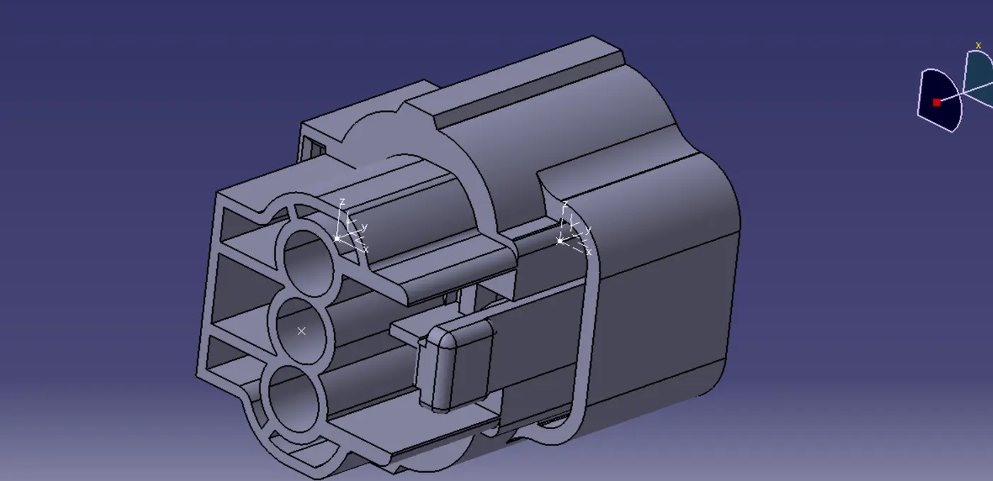
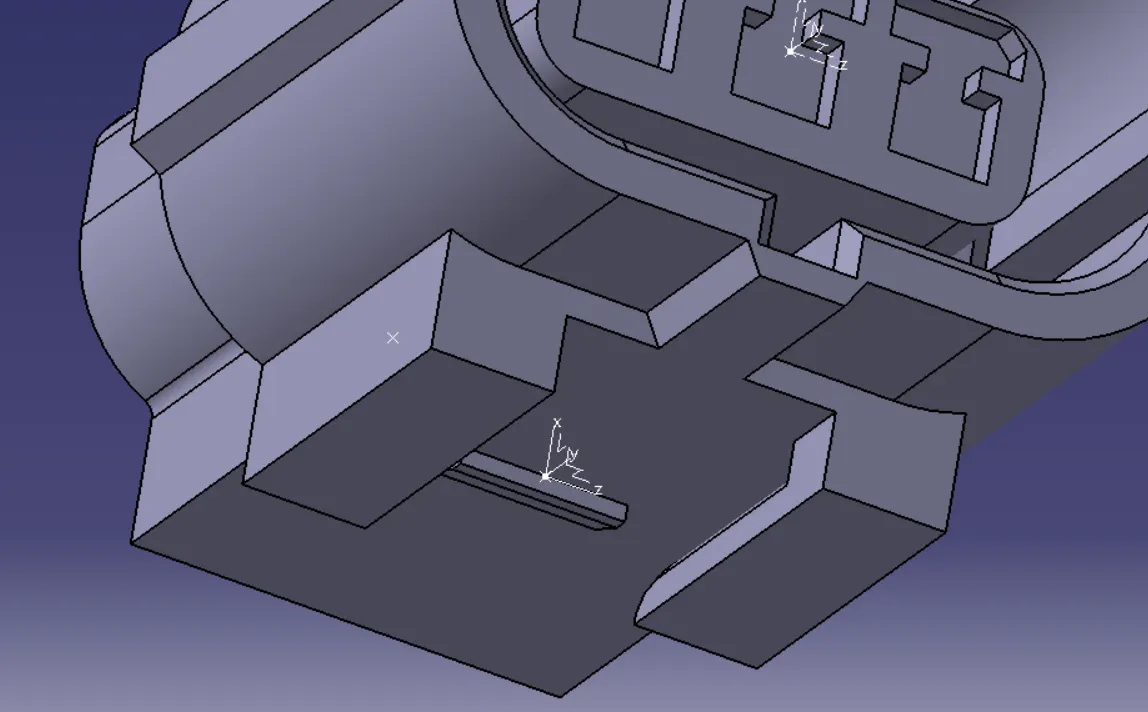
isometric views of connectors:
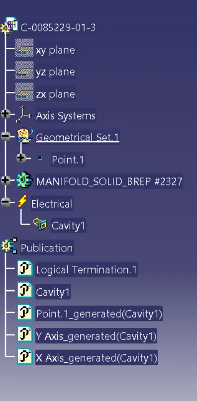
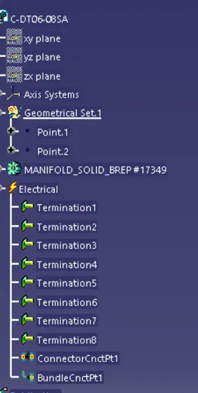
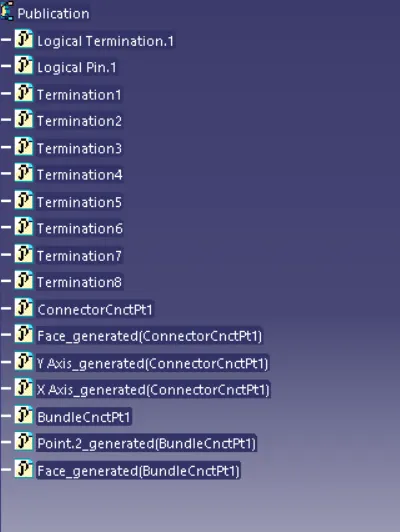
Deutsch DT06 – 08SA
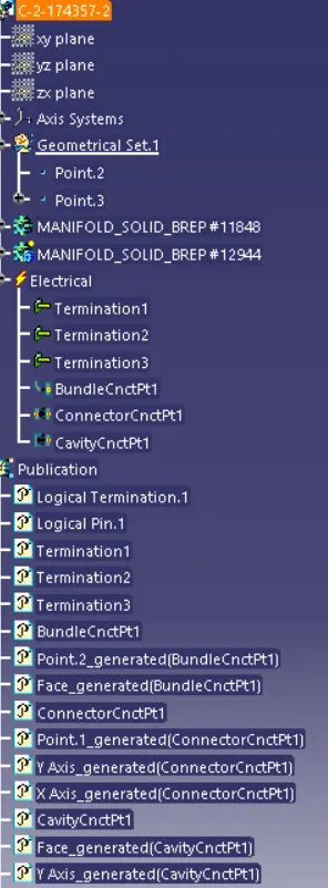
Tree structure
Tyco 174357-2
Tree structure:
CONNECTOR CLIP:
1. Create the Connector Clip Geometry:
o Open the Part Design workbench.
o Model the clip, ensuring:
§ It has a feature to hold the connector.
§ It includes a mounting feature.
2. Switch to Electrical Part Design:
o Go to Start > Equipment & Systems > Electrical Part Design.
o Open the clip part created in the Part Design workbench.
3. Define the mounting equipment:
o Select part model.
o Click on the part.
4. Define the cavity :
o Select cad part.
o Choose the face or surface where the connector will be held.
o Specify the orientation of the cavity.
5. Save the Clip:
o Save the clip part with its electrical properties for use in harness assemblies.
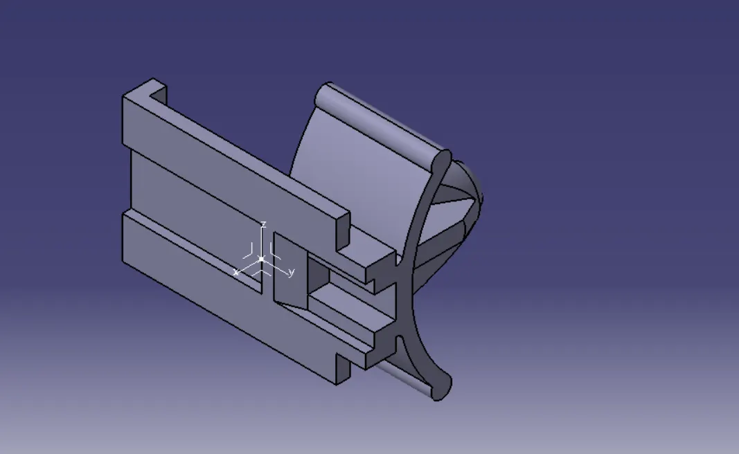
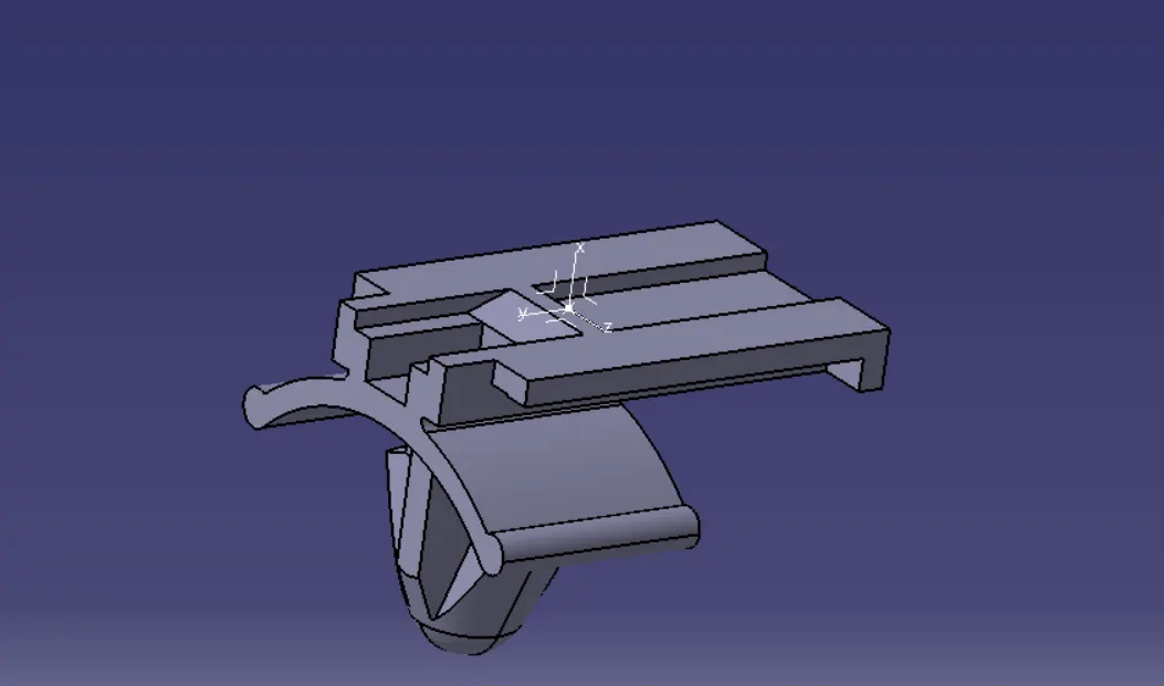
views of connector clip:
Tree structure