Wiring harness design in CATIA V5 - 3D modeling Week 2 Challenge
Challenge 1
Download following connectors & Connector clip cad data from given link & define it as Electrical Connector using Electrical Part design Workbench. Define all the necessary properties to Connectors & Clip.?
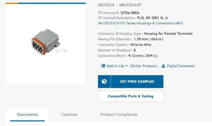
Deutsch DT06 – 08SA ( https://www.te.com/usa-en/product-DT06-08SA.html)
Tyco 174357-2 (https://www.te.com/usa-en/product-2-174357-2.html?source=header-match)
Tyco 85229-1 – (https://www.te.com/usa-en/product-85229-1.html?q=85229&source=header)
A)
To Download following connectors & Connector clip cad data from given link & define it as Electrical Connector using Electrical Part design Workbench. Define all the necessary properties to Connectors & Clip
Deutsch DT06 – 08SA ( https://www.te.com/usa-en/product-DT06-08SA.html)
Tyco 174357-2 (https://www.te.com/usa-en/product-2-174357-2.html?source=header-match)
Tyco 85229-1 – (https://www.te.com/usa-en/product-85229-1.html?q=85229&source=header)
The typical design of the EDS system is Staten below
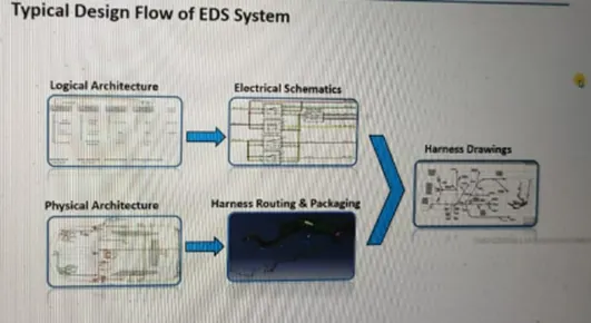
Defining of connector:
We need to define the connector by following the below steps.
- Download the connector data.
- Create required geometrical parameter.
- Define part as electrical connector.
- Define bundle connection point.
- Define connector connection point.
- Define cavity connection point.
Defining the mounting clip:
- Download the clip 3d data.
- Create the geometry parameter.
- Define the part as mounting component.
- Define the part as cavity.
- Defining the connector is described below
Downloaded the cad data from the supplier's website and the images are shown below.
Housing of female terminals
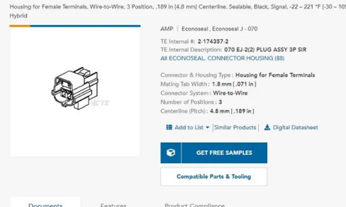
Wire to wire position system
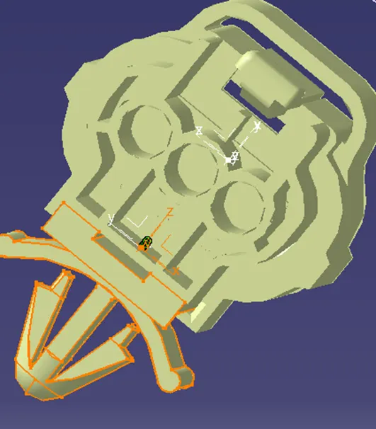
Mounting clips:
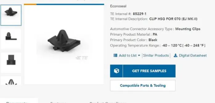
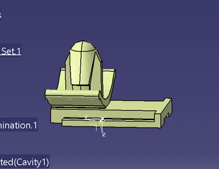
The connector clip is ahown below and the required axis is defined for the locking
Reqired parameters for connectors
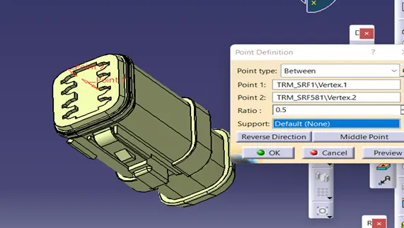
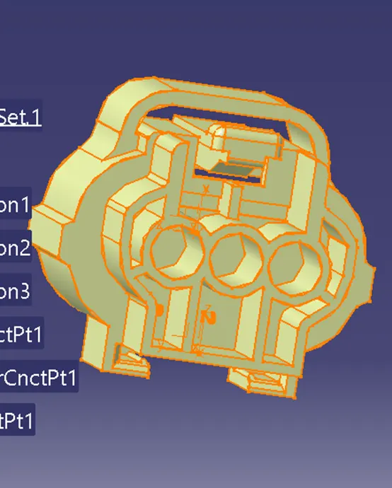
Then we have to put the axis system on the created points of the connectors with same orientation to ensure the correct assembly of the components. Defining the part as connector using the define connector command by selecting the command and selecting the component
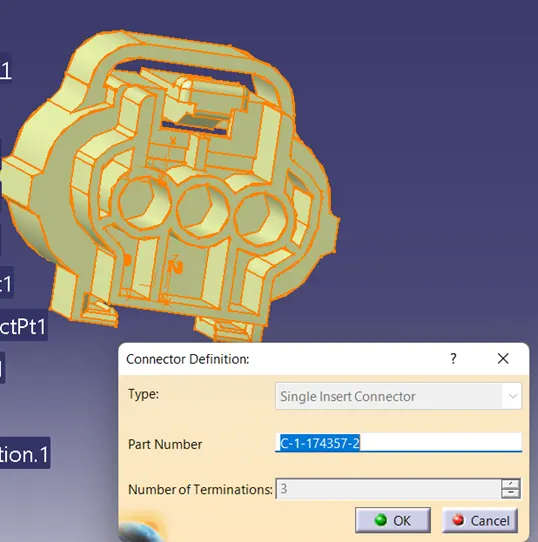
Define the connector connection point and select the required geometry inputs for connector connection
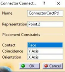
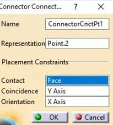
After defining the connectors we need to define the clip also, defining the clip also has various step in it.For clip we need to define it as mounting component, and select the required input needed for defining it as a mounting component
Cavity definition
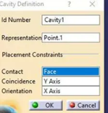
The parts are going to mate by using the connection and disconnect command and the assembly part is shown below
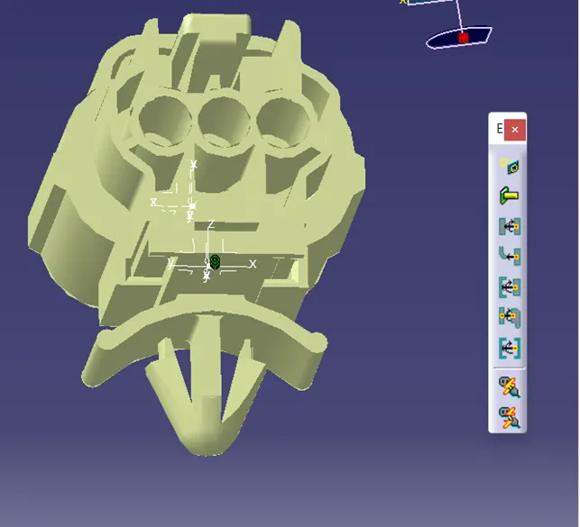
The assembly is joined by using the connection command where it has can be done in 2 ways
Snap command
Manipulation command
with this we can make the mating surfaces easy
reference:
te.com
skill lync vedios