Wiring harness design in CATIA V5 - 3D modeling Week 2 Challenge
1. Deutsch DT06 – 08SA
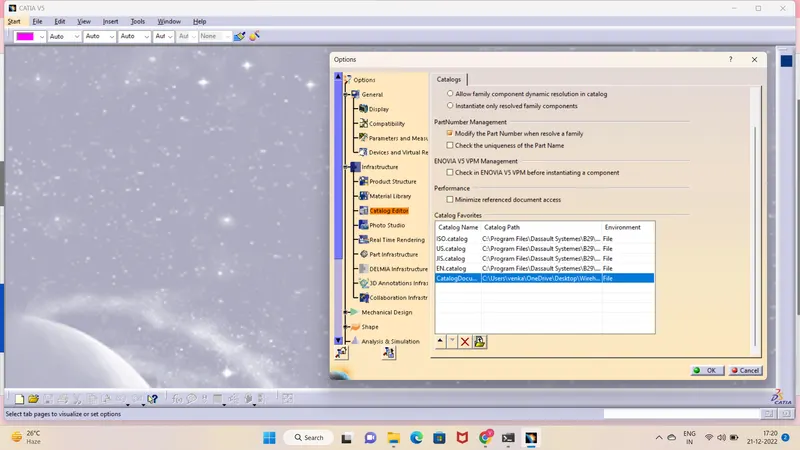
Create the Catalouge settings in option tab before we start the process .
Connector connection point:
Craete Axis System with respect to the point which we have created and defining the axis direction.
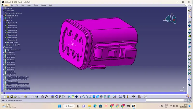
z axis : - pointing across the connector from left to right
y axis :- pointing across the connector from front facing of the connector
x axis :- pointing across the connector towards the locking mechanism of clip.
Bundle Connection Point
Switch to 'Electric Part Design'
Define the part as connector in catia, give no. of termination as 8 because we have 8 entry points for wire.
2.Tyco 174357-2 & Tyco 85229-1
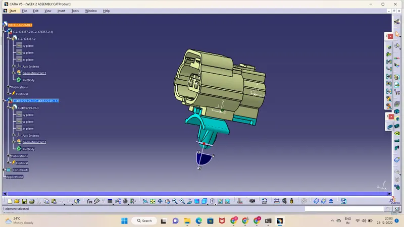
Tyco 174357-2 :
- Create midpoint
- create Connector connection point
- create Connector connection axis system
- create cavity connection point
- create cavity connection axis system
- Switch to Electric part design and define part as connector
- Define Connector connection point and cavity connection point
Tyco 85229-1 :
- Create midpoint
- create cavity connection point
- create cavity connection axis system and orientation should be same as in connector
- Switch to Electric part design and define part as Mounting Equipment
- Define cavity connection point
Electric Assembly Design
- Import Connector and cavity / mounting clip.
- Select Defing Eelectric connection
- select cavity and then connector.