Week 9 Tension and Torsion test challenge
AIM :
To Perform a Explicit Dynamics Simulation for Tension & Torsion testing on a given specimen by using ANSYS Spaceclaim.
OBJECTIVES :
Adding & Assigning the appropriated material into the model.
Create a new coordinates systems for meshing.
Discretize the specimen.
Applying the Boundary Condtion on it.
Extracting the output which are required.
INTRODUCTION :
Tensile test :
A Tensile testing is also known as tension testing is a fundamental material science and engineering test in which a sample is subjected to controlled by tension until a model has to be failure.
From that properties that are directly measured via tensile test which are ultimate tensile strength, breaking strength, maximum elongation and reduction in area. From these measured properties can also be determined which are Young's modulus, poisson's ratio, yield strength and strain hardening characteristics.
Torsion Test :
A action of twisting or state of being twisted of the object due to applied torque, especially one end of the object is fixed and other end is relatively move.
PROCEDURE FOR ATTAINING THE OBJECTIVES :
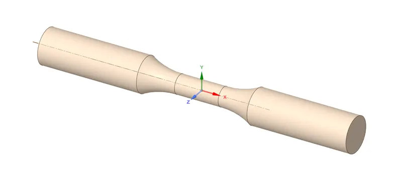
I) CAD Model :
II) Material Adding & Assigning :
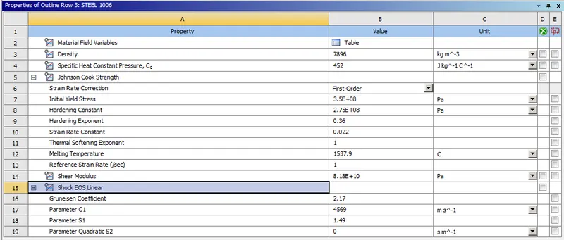
In this analysis, we gonna use "STEEL 1006" as a material for this component.
In order to add the material into the material list, we have to first add the material from the engineering data source. Thereafter, we should assign that material into the model.
This material is remains same for both case 1 & 2.
III) Create a new coordinate systems :
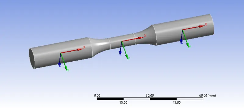
We have to create a new coordinates on both support for sphere of influencing meshing.
After creating the new coordinates, it has been looks like as shown in below image.
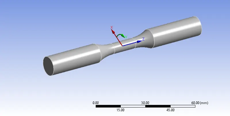
We have to create a additional coordinate system where at middle portion for case 2 alone. Make sure, have to change into Y rotational axis about z axis like as shown in below.
IV) Meshing :
To Split the geometry into finite number of elements that are connected together with nodes, this process is called discretization and that framework or rather let's say collection of nodes and elements is defined by whole model is called meshing. This Finite element method is widely used for solving partial differential equation in different physical field such as Structural problem, Heat transfer problem, Fluid flow problem, Electro magnetic Analysis & Acoustics Analysis.
By using this model, we gonna perfom two diferent analysis which are Tension & Torsion. So, that we have to discretize the model according to the simulation. For Torsion test, we have to consider on middle portion for which capturing the accurate results.
Case 1 :
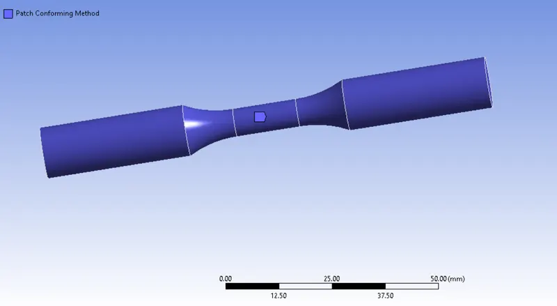
i) Patch Conforming Method :
Since, this given model is circular in shape, so better we perform with tetrahedral elements for meshing.
Select the whole model with solid selection option, choose the method that we gonna perform which is "Tetrahedrons" along with "Patch conforming" method is selected by default.
ii) Face Sizing on Left side :
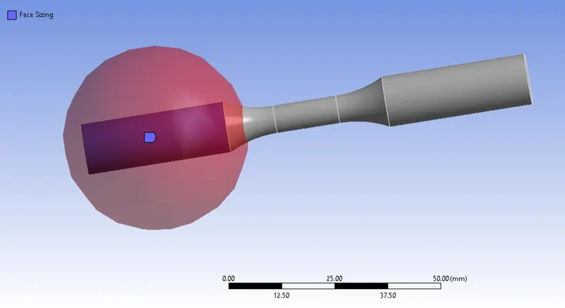
Select the faces properly & followingly switch to "Sphere of Influence" method with appropriated coordinate systems as like as shown in below image.
Provide the Sphere radius is 22 mm and give the 3 mm.
iii) Face Sizing on Right Side :
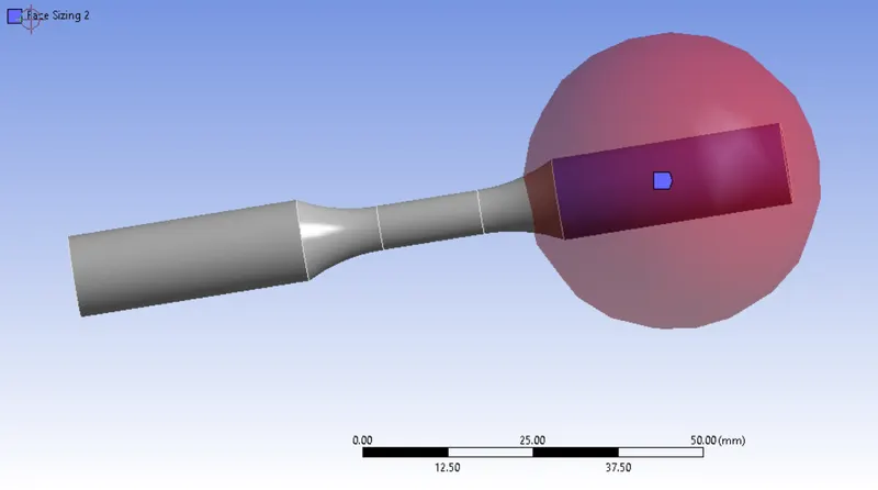
Similarly, do it on another end as well like how we did in previous one.
Case 2:
For Case 2, we have to capture with more refined mesh as than compared to previous case. Because, angular deformations are generated on where middle portion of the part.
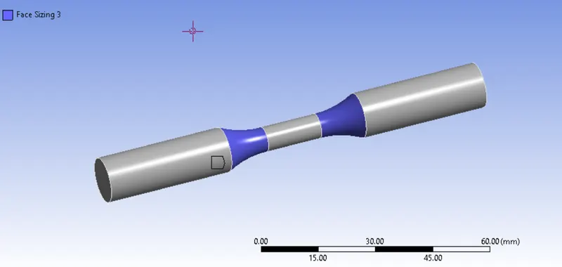
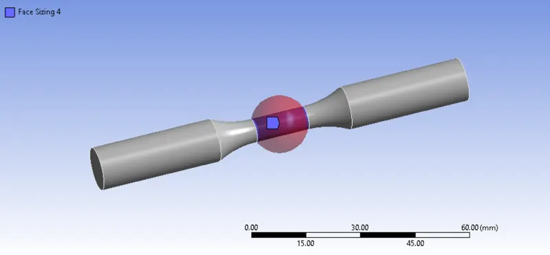
Face Sizing on the taper surface :
Select the tapered surface like as shown in below image and meshing with element size of 1.5 mm.
Face Sizing on the middle portion :
Select the middle portion surface, change to "sphere of influencing" as a definition type.
Give the sphere radius is 8 mm and Element size is 1 mm.
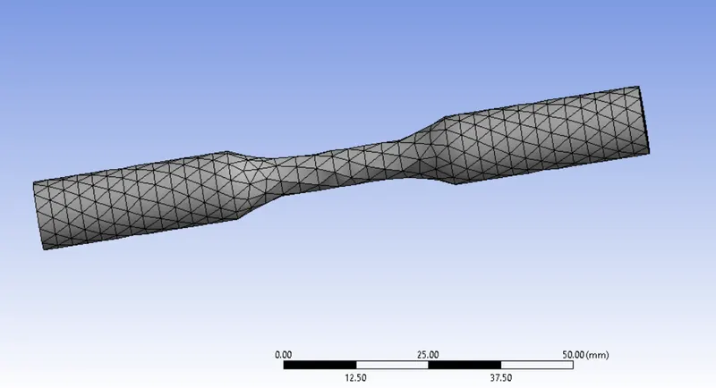
Meshed Model for Case 1 :
A model is meshed with Tetrahedral Elements.
Number of Nodes = 683
Number of Elements = 2450
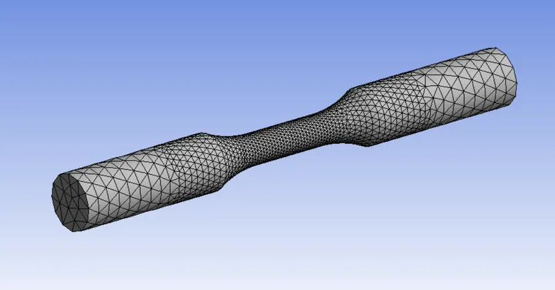
Meshed Model for Case 2 :
For case 2 also be meshed with Tetrahedral Elements.
Number of Nodes = 4541
Number of Elements = 20799
V) Analysis Settings :
Number of Steps = 1
Load step type is "Explicit Time Integration"
End Time = 0.0001 sec
Maximum Energy error = 0.1
Initial, Minimum & Maximum time steps are set to be "Program Controlled", it has to find optimum time step value.
Time Step Safety factor = 0.9
And remaining option are keep as it is.
Boundary Condition :
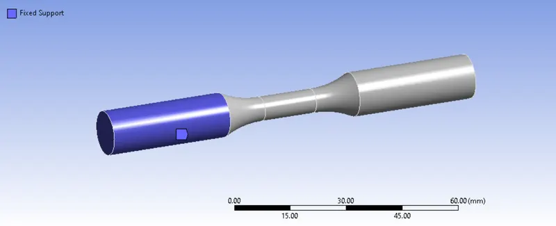
Fixed Support :
While performing the simulation like tensile or torsion, have to fix on one end like as shown in below image.
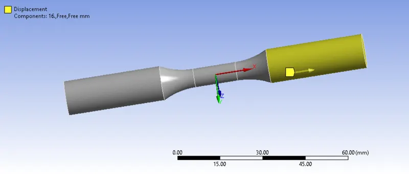
Linear Displacement for Case 1:
While performing the tensile testing, have to pull on the x direction alone.
Select the faces like as shown in below, apply the displacement value for x direction alone from 0 to 16 mm
Angular displacement for Case 2:
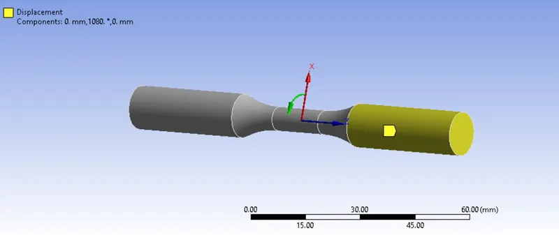
While performing the torsion testing, have to rotate the model on either direction about an z axis.
Select the face like as shown in below, apply the angular displacement value from 0 to 1200 degree.
RESULTS :
CASE 1:
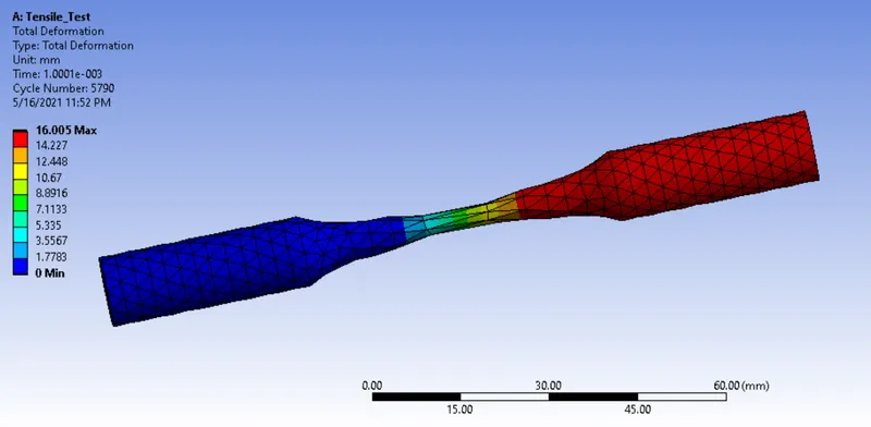
Total Deformation :
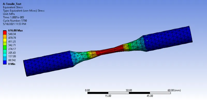
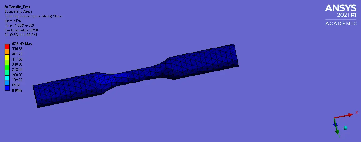
Equivalent Stress :
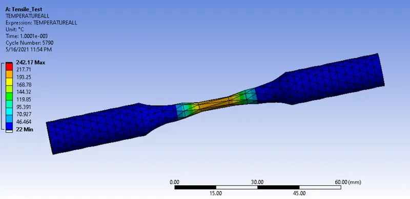
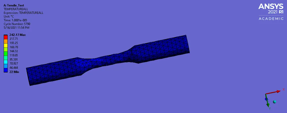
User Defined Temperature :
CASE 2 :
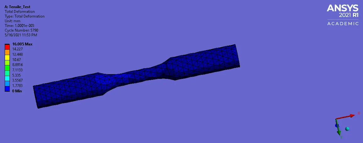
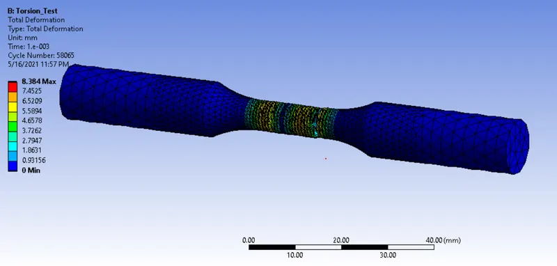
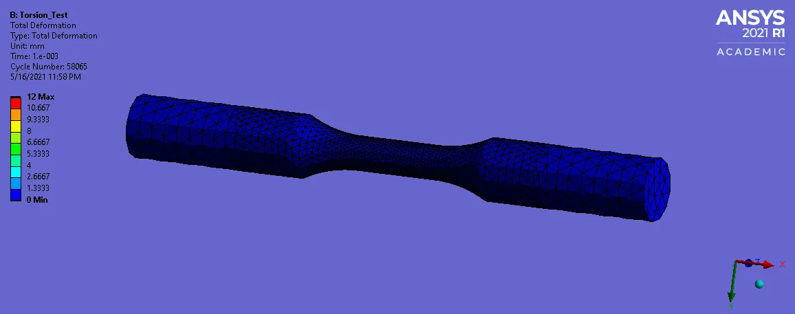
Total Deformation :
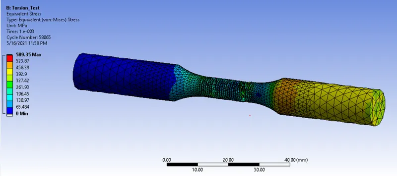
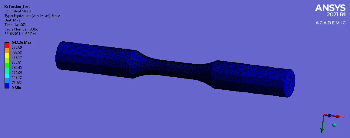
Equivalent Stress :
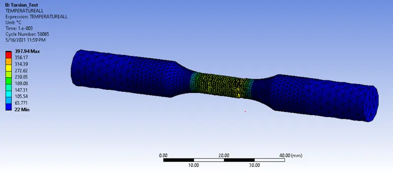
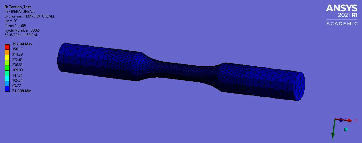
User Defined Temperature :
CONCLUSION :
For Tensile Test,
Total Deformation = 16.005 mm
Maximum Equivalent Stress = 616.88 Mpa
Temperature = 242.17 degree celsius
For Torsion Test,
Total Deformation = 8.384 mm
Maximum Equivalent Stress = 589.35 Mpa
Temperature =397.94 degree celsius
A Total deformation is attains higher in tensile or tension test. Because, when we pull away the component from one side along with fixed on other side. It may cause more deformation.
A Maximum equivalent Stress is higher for tensile test, because cross sectional area of component were reduced while pulling the component away.
Whenever, a material particle are change the shape while applying the load on it, that time has to be release some energy in form of temperature. A Temperature is higher in while performing the torsion test.
Learning Outcome :
I Learnt How to perfom the simulation by explicit dynamics.
I Learnt How to Create a cylindrical coordinate.
I Learnt How to extract the required output from worksheet.