Week 9 Tension and Torsion test challenge
AIM: - PERFORM A SIMULATION OF TENSION AND TORSION TEST ON A GIVEN SPECIMEN.
Objectives:
Perform a tension test by displacing one end of the specimen by 18 mm while the other end is fixed.
Perform a torsion test by displacing one end by 1200 degrees while the other end is fixed.
Obtain Total Deformation, Equivalent Stress, and the Temperature of the specimen for both the operations.
TENSION TEST SEET-UP:
To begin the analysis, open the Explicit dynamics Analysis from the Analysis Systems of the Ansys Workbench.
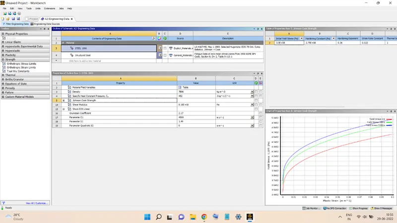
Go to Engineering Data, open the Engineering Data Sources and select the Explicit Materials library and add Steel 1006 into the project library. The properties of Steel 1006 are shown below:
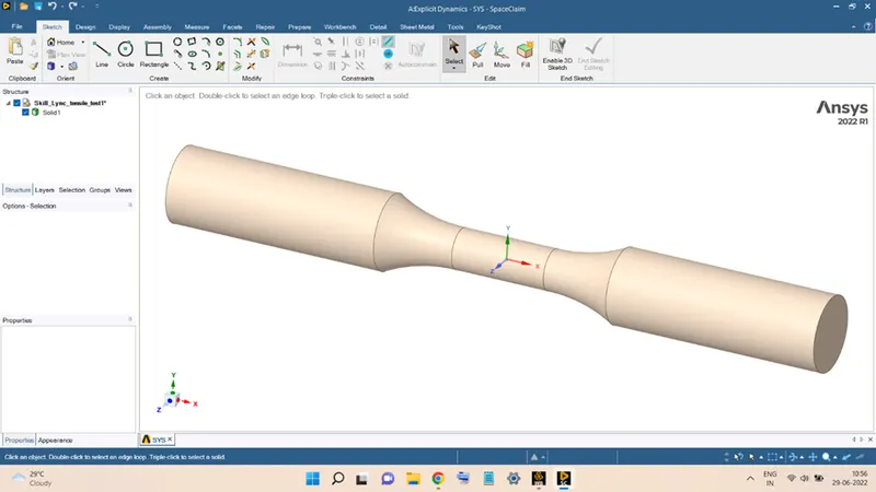
Import the geometry into the project environment, double-click on Geometry to view it in SpaceClaim:
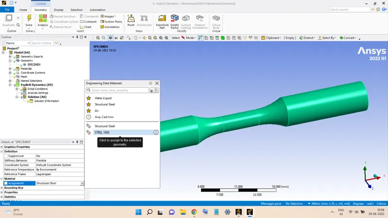
The geometry is assigned the material properties of Steel 1006.
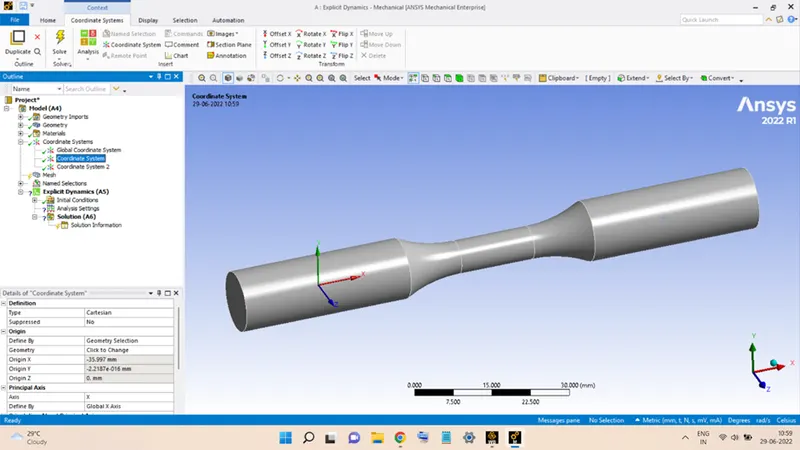
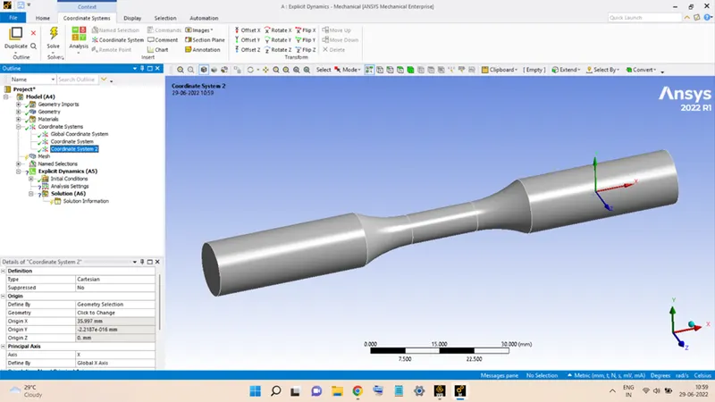
Two new cartesian coordinate systems were added to the geometry, as shown below:
During the meshing of the model:
The Method for the meshing chosen was Tetrahedrons.
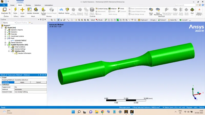
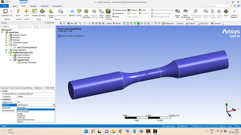
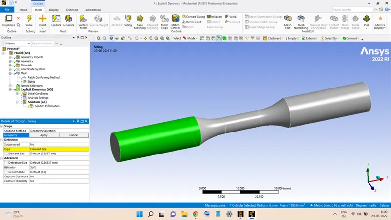
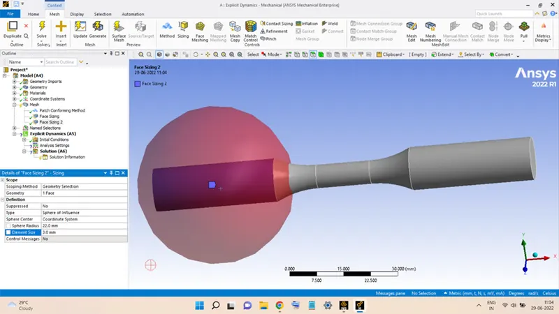
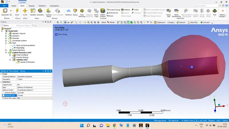
Sphere of Influence was added on the two ends of the SPECIMEN having Center on the newly created Coordinate Systems and Radius being equal to 22 mm and the Element Size is kept as 3 mm.
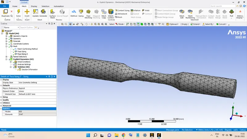
The model after meshing looks like this:
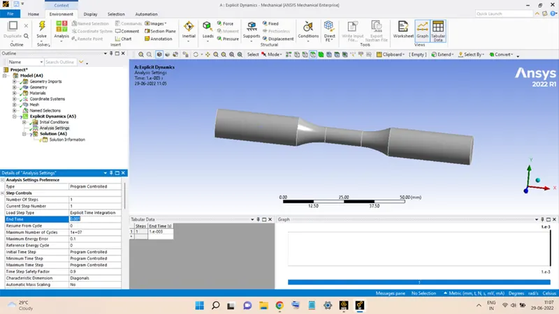
In Analysis Settings, the End Time was set to 0.001 sec.
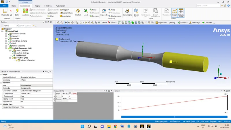
One end of SPECIMEN is supplied with a Displacement Load along the X-Axis that will displace it by 18 mm.
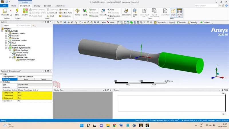
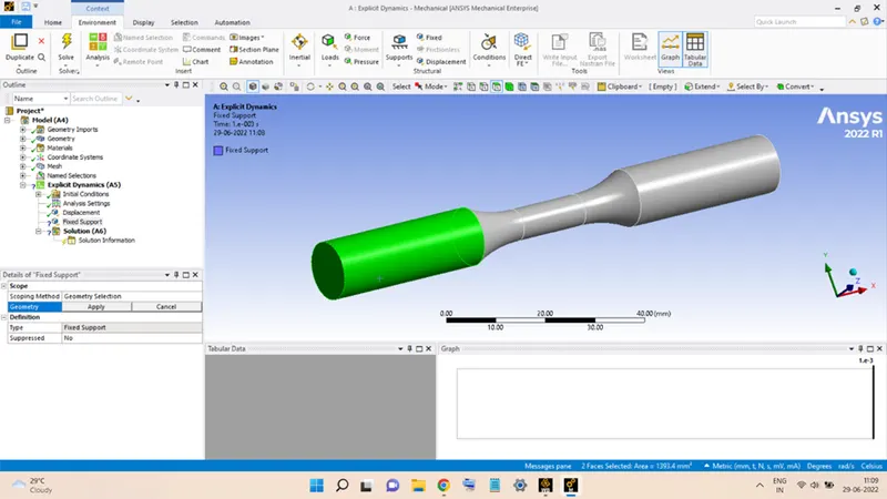
The other end is supplied with a Fixed Support, as shown below:
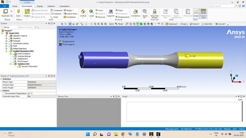
The model is ready for the Tension test Simulation, hit Solve to begin the analysis.
TORSION TEST SET-UP:
To set up the model for a torsion test, first, duplicate the tension test project and then right-click on Model and select Edit to open the model in Mechanical Module.
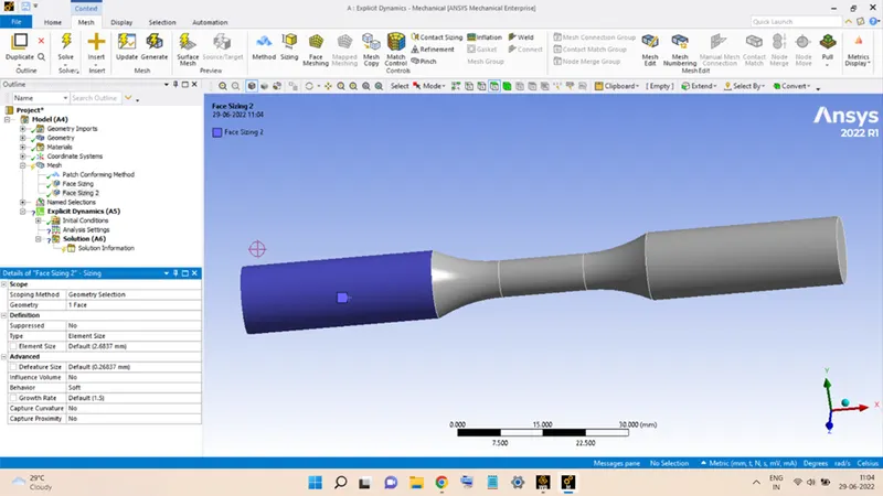
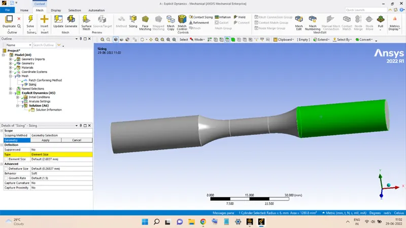
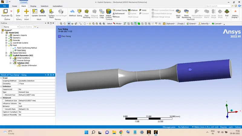
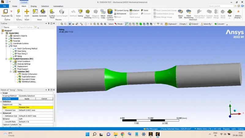
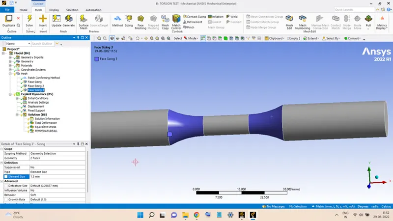
Go to the Mesh section and provide the Face Sizing with an Element Size of 1.5 mm to the surfaces shown in the figure below.
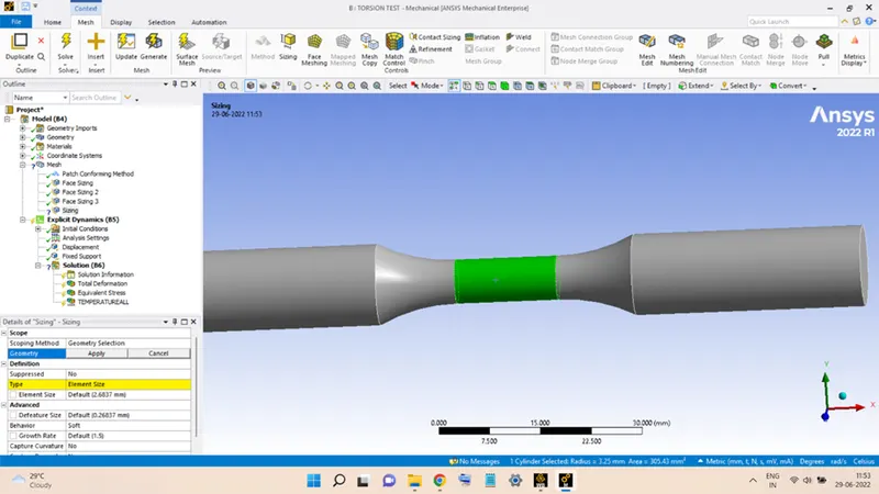
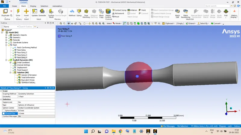
A Sphere of Influence is added to the central portion of SPECIMEN having a Radius equal to 8 mm and an Element Size equal to 1 mm.
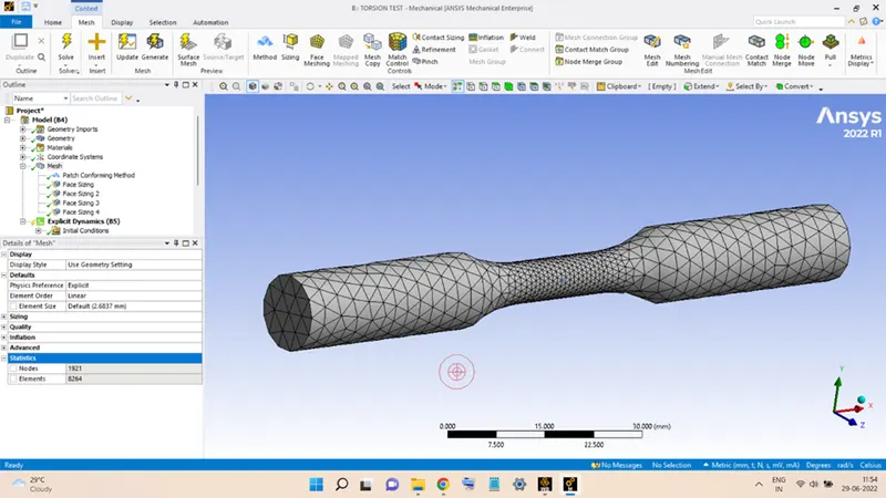
The model after meshing will look like this:
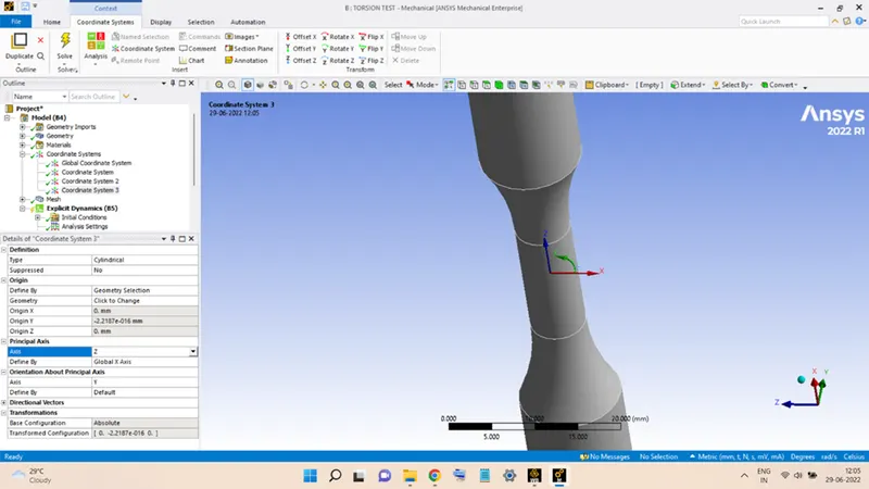
A Cylindrical Coordinate System is added to the model in the center portion, such that the Y-Coordinate represents the angular position and is aligned with the SPECIMEN as shown in the figure:
The Angular Displacement of 1200 degrees is added to the model about the Y-Axis of the newly created cylindrical coordinate system.
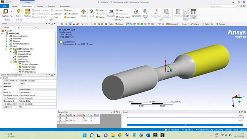
Rest all the things are the same as were for the tension test and hit Solve to run the analysis.
RESULTS:
TENSION TEST:
Stress:
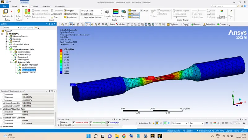
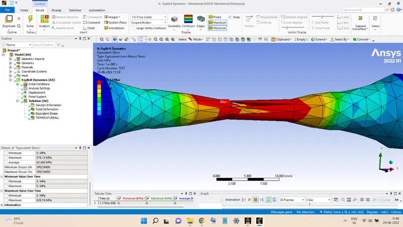
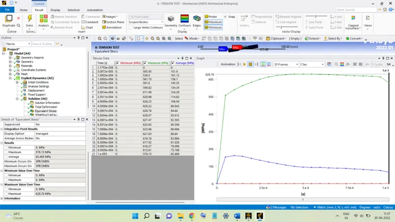
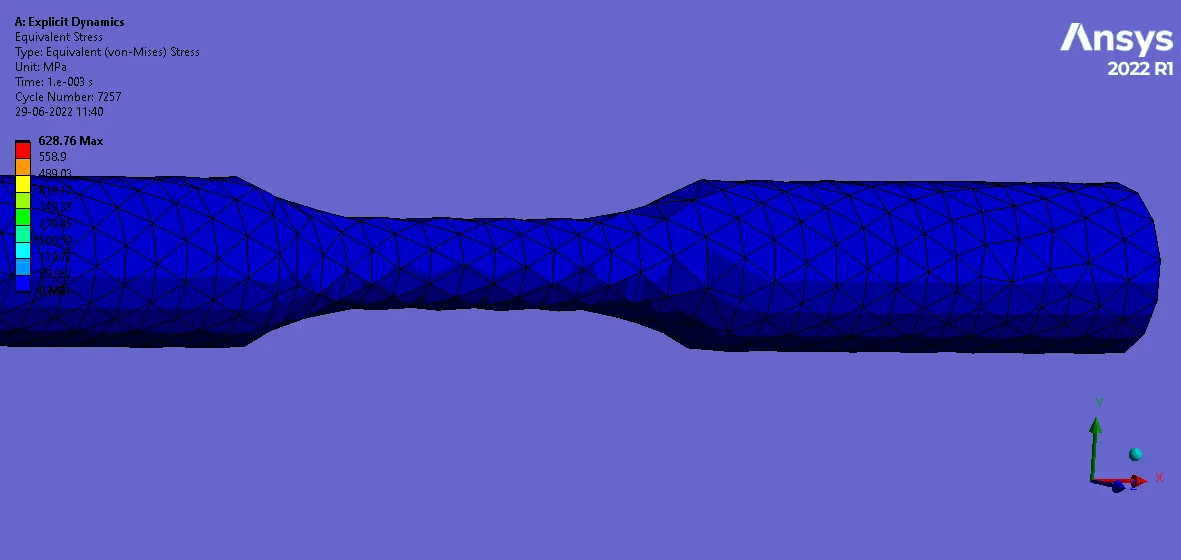
The above figures show the variation of the stress developed in SPECIMEN during the tension test.
It can be seen that the SPECIMEN is failed and is about to break into two parts.
The elements can be seen to be being pulled apart and are forced to break the bonds. Some of the elements have already broken these bonds due to which there is empty space in some places instead of the elements.
The elements can be seen to be forming a Cup-Cone region near the center, but it is not fully developed as some elements are still intact. If the displacement is increased little further then a more visible Cup-Cone region will be generated.
The maximum value of the stress is equal to 628.76 MPa.
Deformation:
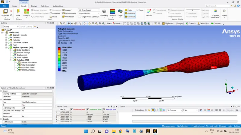
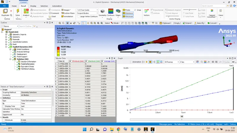
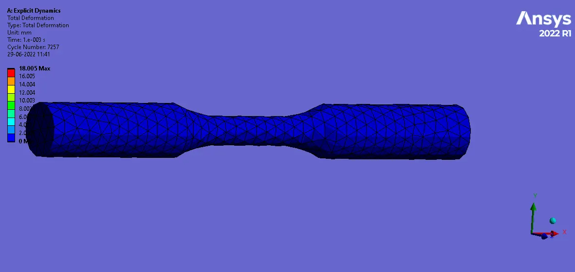
The deformation during the tension test is shown above, the maximum deformation is seen to be slightly more than the given one, and is equal to 18.005 mm.
Temperature:
This is a User Defined Result added, after successful completion, from the Worksheet.
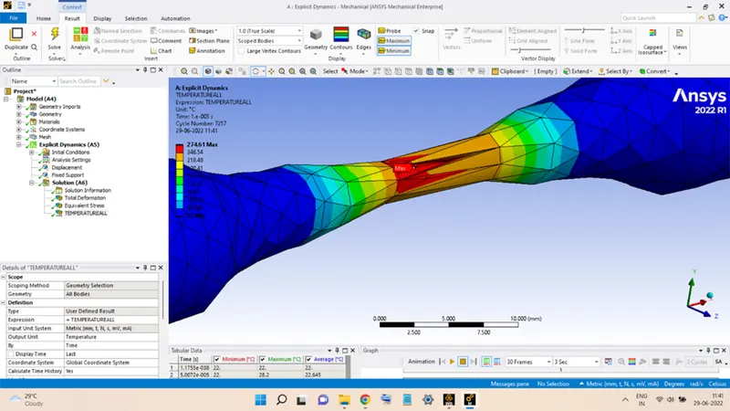
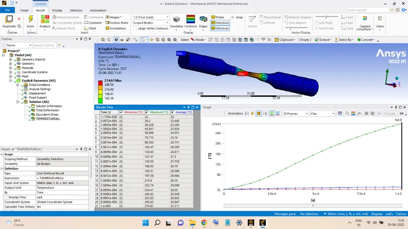
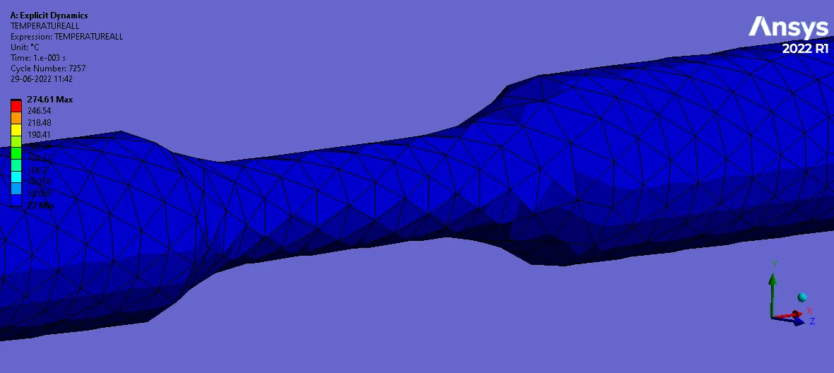
Since the elements are deformed adversely and bonds are broken during the tension test the energy within SPECIMEN is released in form of heat which causes the temperature to rise near those areas only. This is depicted in the above figures. Temperature rise is seen in deforming areas only. The most adversely affected region is having a maximum temperature equal to 274.61oC.
TORSION TEST:
Stress:
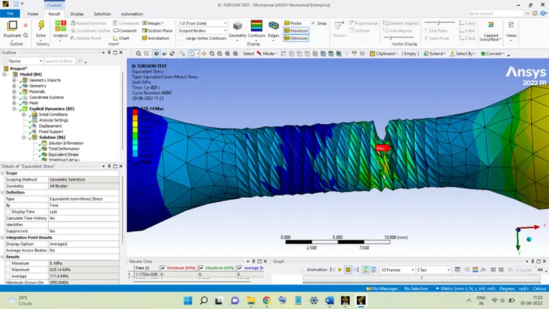
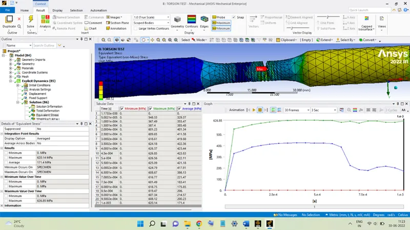
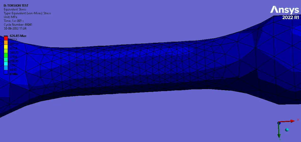
The stress developed during the torsion test in SPECIMEN is shown in the figures above. The figures also depict how the material will fail under the twisting load. There are a few elements that got separated from the body during the torsion test.
The maximum value of stress recorded is equal to 626.85 MPa.
Deformation:
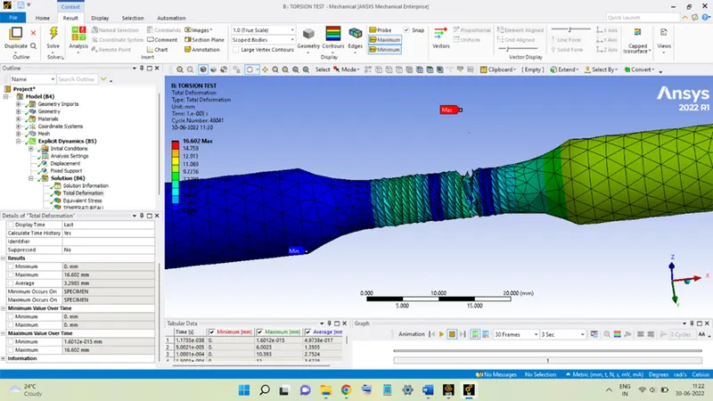
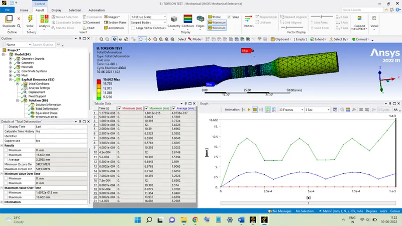
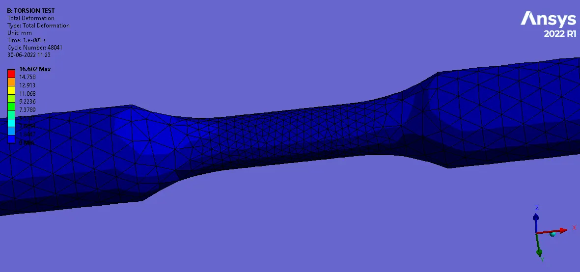
The deformation in SPECIMEN due to the twisting load is shown in the above figures.
The maximum deformation is shown away from the body, it is because there were some elements that separated from the main body during the test.
The maximum value of deformation is 16.602 mm.
Temperature:
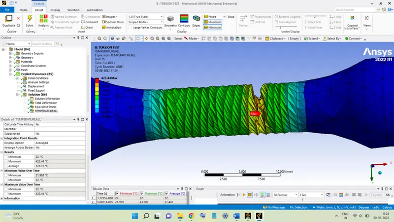
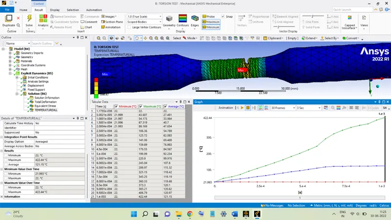
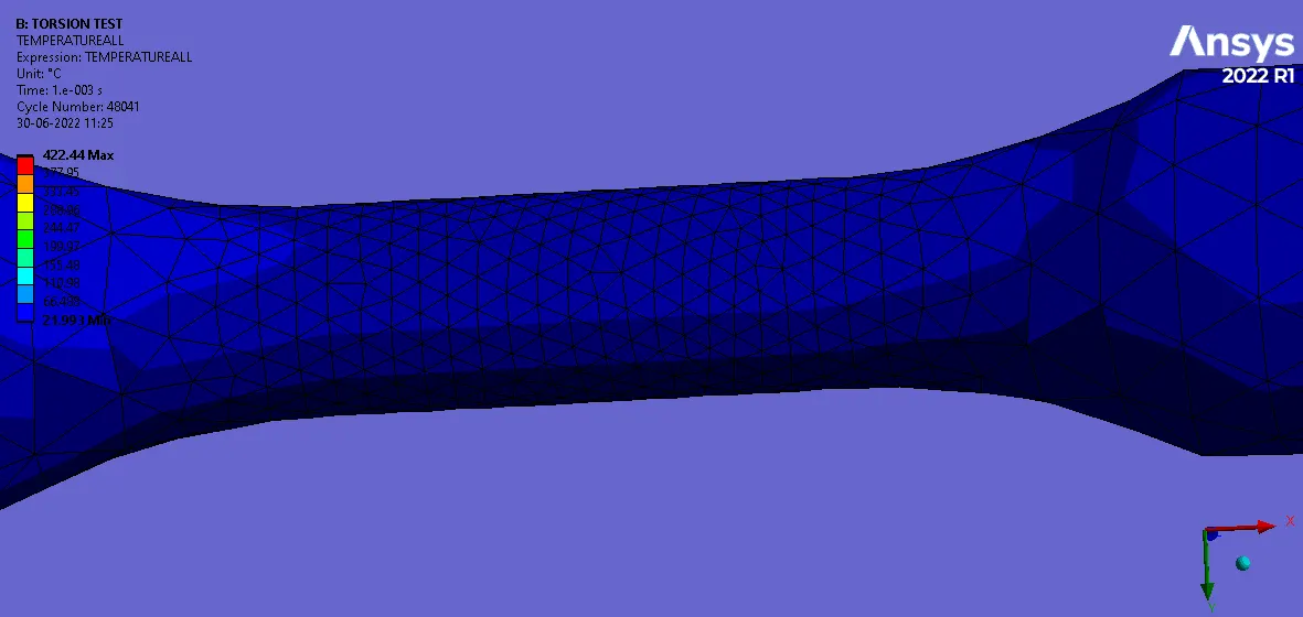
The temperature rise near the deforming regions is shown in the figures above, the maximum temperature reached during the test is equal to 422.44oC.
CONCLUSION:
From the results of both the tests, it can be said that:
The Torsion loading is more severe for any component as compared to the tension loading, since, in both tests, the maximum stresses induced were almost the same, despite the that the temperature for the torsion test reached almost double that in the tension test.
Also, the elements got separated from the body during the torsion test.
So, it becomes mandatory to make the component safe for torsion loads first.