Week 9 - Project - Master Section Development
WEEK 9-PROJECT-MASTER SECTION DEVELOPMENT
AIM:
A class surface and master section and addding thickness. Cover including ribs and locators using the aim of this project to model the pillar. Component along with the required attachment features using the given class A surface and the master section component.
INTRODUCTION:
The B-pillar trim are manufacturable and usable in the interior. While manufacturing a part through injection molding a lot of defects can occur on the plastic part which will destroy the look of the panel. the design has to made in such a way that all the errors can be rectified.
This car pillar is actually a sheet metal part which is welded in the BIW of the car. As we can observe from the image above the class A surface on its own has some issues as it does not clear for the minimum draft angle clearance. this cannot be rectified by us as it is provide by the team performing the class A styling surfacing. keeping this in mind we proceed to class B surface creation. We use the given master section of the final component and thereby deciding the offset value for class B surface.
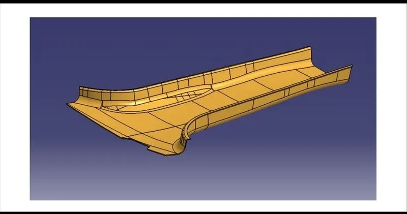
PROCEDURE:
The surface of a component refers to the aesthetic surface which is visible to the naked eye when we observe a body such as car in have some fine finishing and aethectic look to it. As plastic components are injection moulded we need for the core and the cavity.
The direction in which the moulds move apart together which means it serves as the reference to desingn your data up aganist. one more point to be noted here is that the draft is always provided along the tooling axis so that it can easy when the component mould are parted.
We can use the given master section of the final component and thereby deciding the offset value for class B surface. As we can observe from the image above the class A surface on its own has some issuses at it does not clear for the minimum draft angle clearance.
THEORY:
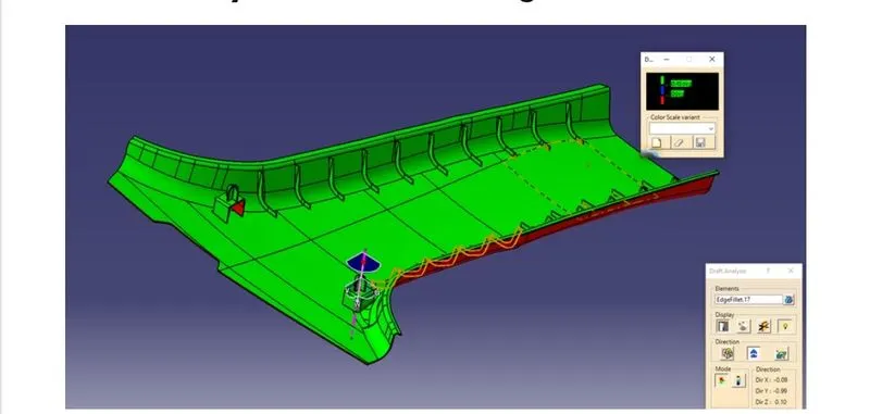
We have been provided with the class A surface and in that surface we create a tooling axis which can be seen in the image above. Now that the tooling axis is obtained we perfrom a draft analysis on the given class A surface.
(TOOLING AXIS,TOOLING AXIS/DIRECTION)
DESINGN LIFE CYCLE AUTOMOTIVE INDUSTRY:
The stages of design life cycle are.
CLASS A CREATION:
After finalizing the concept the sketches are usually worked in software such as Autodesk alias to create class A surface.
CLAY MODELING:
The class A surface is concurrently worked by clay modelers to brainstrom and benchmark the styling of the product and later the cocept is validated by bringing up a rough clay model and then it is passed on to the design team for the preparation of New product design CAD.
NPD CAD:
* Tooling Axis
* B surface creation
* C surface creation
* Closed body creation
* Draft Ananlysis
TOOLOING AXIS:
Tooling axis is nothing but the direction in which the core and cavity opens and closes. Design engineer works is to analysis the class A surface and find out the best possible tooling direction keeping in mind all the draft angle is with respect to the tooling axis so that the component can be easily ejected from the moulds.
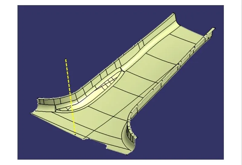
This tooling axis is as this region cannot be cut out using the main tooling axis and hence reqiured a lifter for it. we perfrom a draft analysis for that region as well using the lifter axis as the reference.
B CLASS SURFACE CREATION:
Represent internal and functional surfaces. this cluster exemplary includes derived surfaces created by offset operations from class A surfaces to define the thickness of material. this file it is imported to link class B surfaces automatically in case of styling change.
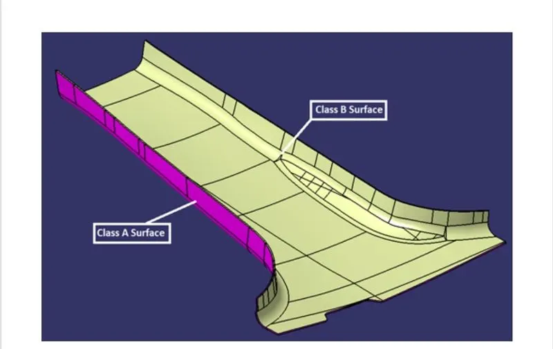
C CLASS SURFACE CREATION:
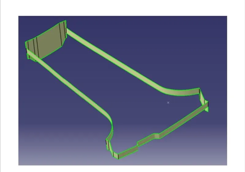
The modified class A surface to obtain the b surface. After B surface proceed creation C surface we use the class A surface boundary and sweep them in the perpendicular while providing the suitable draft along the tooling axis direction.
CLOSED BODY CREATION:
The surface are then trimmed with class B surface to form a closed surface. these surface are hollow we need to close it to from a thick solid component. using the option in part workbench a solid body from the surface can be fromed. this will give us a solid component.
DRAFT ANANLYSIS:
Draft angles are very important in thermoforming product design. if the product is fromed onto a female or negative mold it shrinks aways from the mold sidewalls. As a result true female or negavtive product can be thermoformed with vertical walls having zero draft angles.
The draft small draft angle is to be provide for each and every surface of the component from the moulds without any defects. Draft is the angle in which the part is tapered to allow it to release.
Most of the part reqiure minimum degree however degree are widely accepted in plastic component designed product are manufacturable with reqiured condition or not. the draft direction at any point corresponds to specfied values.
CREATION OF RIBS:
(+x,-x,+y,-yand -y)
* Translation Movement along X Axis
* Translation Movement along Y Axis
* Translation Movement along Z Axis
* Rotational Movement along X Axis
* Rotational Movement along Y Axis
* Rotational Movement along Z axis
DOG HOUSE:
Dog house is as use to follow the master section which we need to follow the given input. the top surface and the supported walls of the dog house on which the locator is laid is created by simply extracting the lines from the master section ina sketch and extruding it to a certain length as shown in figure.
That are mounted on the doghouse to increase their strength and avoid the sink marks.
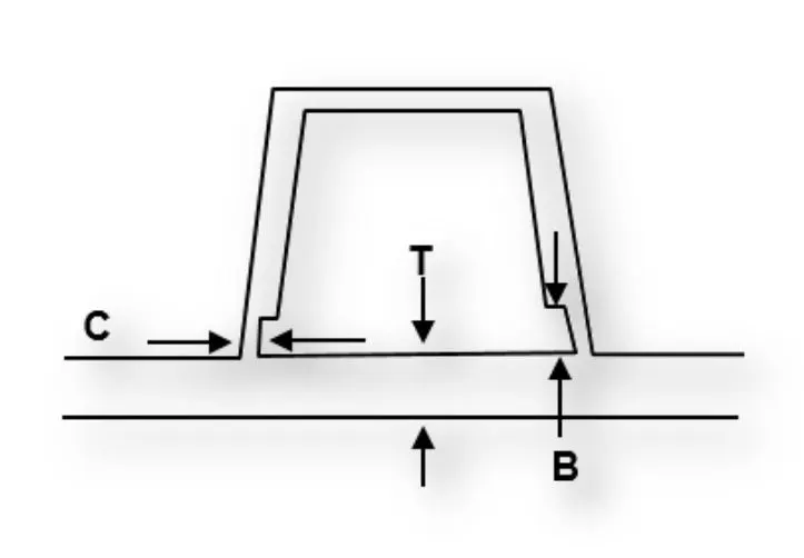
1. dog house wall thickness intersection ( C )
2. should be 40%
3. main wall stock ( T )
4. height of ( B )
5. between 3.0-6.0mm
RIBS:
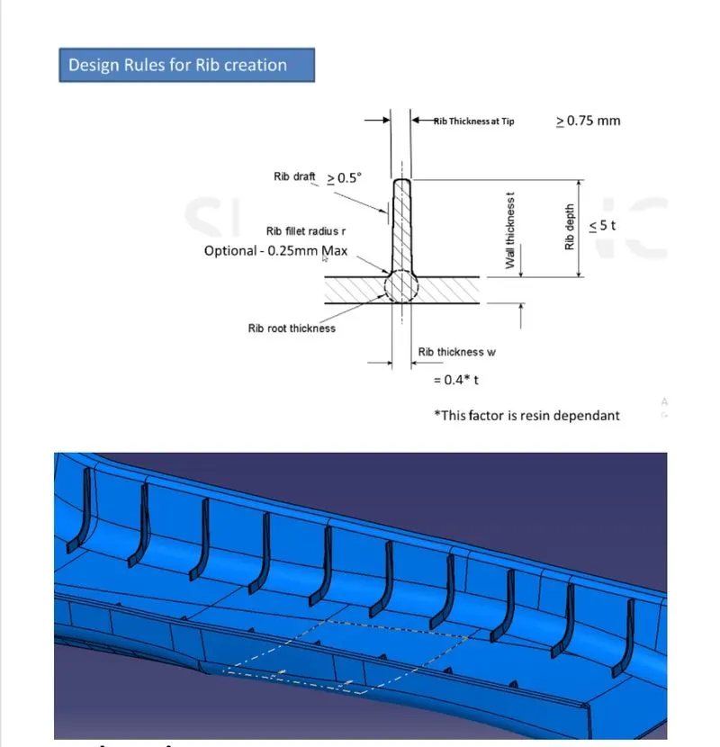
We have attached images for the draft analysis performed on the interior and the exterior of the component above. finally we create the sketch for ribs while maintaining a distance of between two ribs till the end of the component.once they are extruded the necessary draft and fillets are provided and finally a draft analysis is done on the ribs.
SIDE TOOLING AXIS:
DRAFT ANALYSIS WRT TOOLING AXIS:
CONCLUSION:
The given class A and master section with all the engineering featured with adequate design rules were respected and maintained. Draft analysis was performed for the built model and it could be seen that the draft manufactring of the component. B side features were created for the component as per the design rules. was created as per the automotive standard using catia v5 software. also check the draft for other using the main tooling axis.