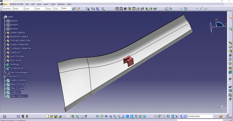
Week 9 - Project - A pillar Design with Master Section
A PILLAR DESIGN WITH MASTER SECTION
AIM :
-
Create A PILLAR DESIGN WITH MASTER-SECTION through the given Class-A surface. To begin with, the tooling axis for the given Class-A Surface should be created meeting the requirements of the draft angle and at the end perform the Draft analysis on the model.
DESIGN PROCEDURE :
- Checking Class A input for imperfections
The input class A surface is checked for discontinuities and joined together to get complete class A surface as one.
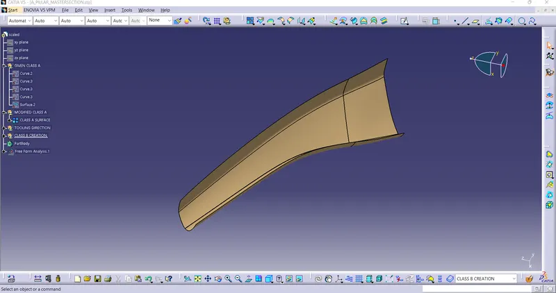
- TOOLING AXIS :
The tool axis is the parameter which decides whether the tool enters into mould or not as as it denotes the draft clearance angle where a moulded part is easily removed from the mould.
Procedure for creating tooling axis
- Firstly we will be given with a class A surface which is looked as a asthetic and a smooth finish which is created with a Alias software workbench which is also known as a free imagination surface.
- For that class A surface we need to check a boundaries first to check any unattached faces is present in that surface.
- The below is the image of a class A surface which is given as a input.
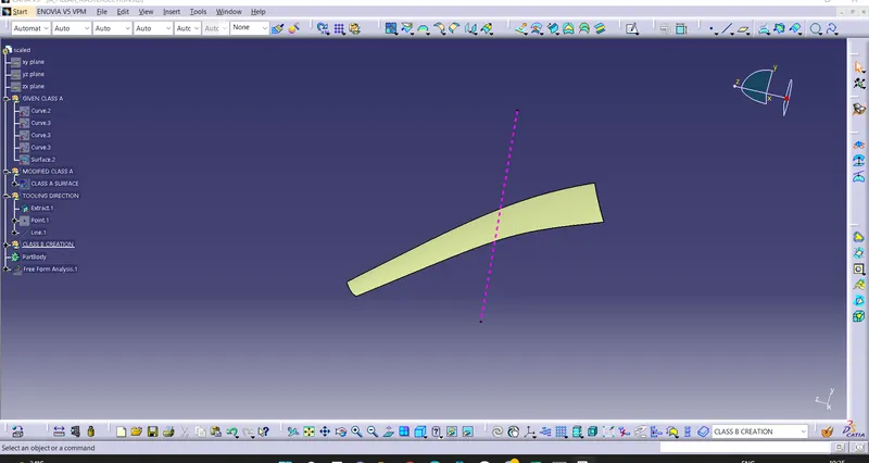
- So next we need to take a dummy tool axis to get a real tool axis.
- Next we take inclined lines to the surfaces we assume that draft is required.
- Then we intersect the both the lines and the bisecting line will be the tooling axis.
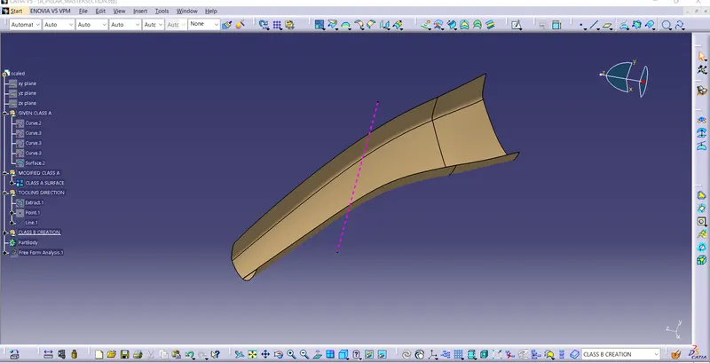
DRAFT ANALYSIS OF GIVEN CLASS A
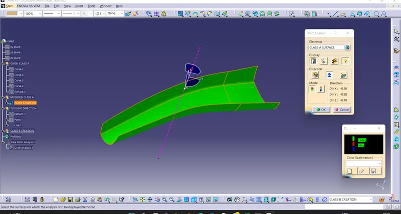
- No parts can be ejected from the tool if it is having a straight 90 degree profile from its base surface. A small draft angle is provided to each and every area of the component in order to get an easy removal of the component from the tool.
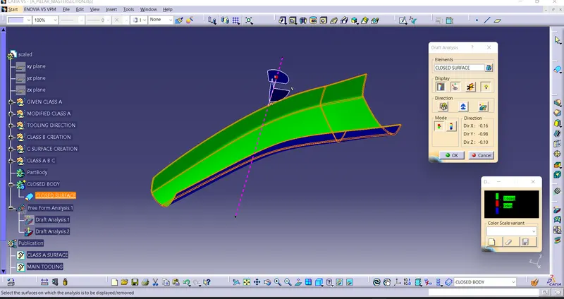
- Draft analysis technique is used to analyze whether our part model created in cad is manufacturable based on the draft condition applied. Here the part should get easily removed from the panel dies (in case of Sheet metal part) or Mold (in case of plastic).
- Here we are providing a direction in which components should eject inorder to get an easy removal of components from the tool. In other words it also lets us know whether the model is having a draft angle and how much is the draft angle from the tool direction.
- B surface creation
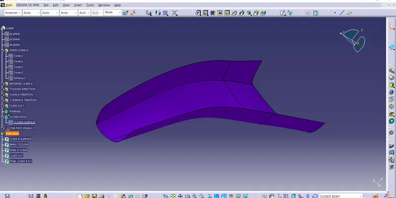
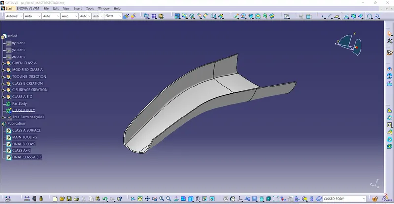
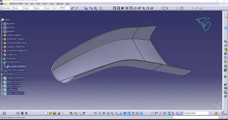
As usual, B surface is created using standard procedure by extract, untrim, extrapolate and offset commands. B surface of this coin holder is divided as base, side walls, top wall and outer surface. B surfaces of all these sub parts are created and trimmed together to join as single surface.
The offset distance is kept 2.5mm as component thickness is 2.5mm
- Class C surface creation
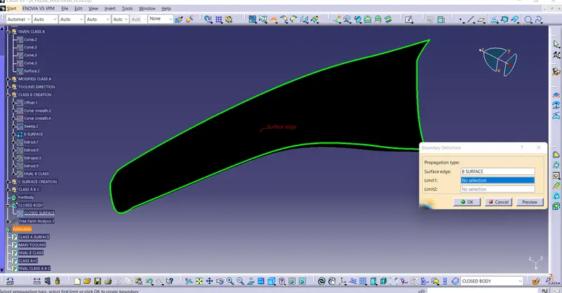
Class C surface for this component is created using sweep command. All the ends of component surface are facing downwards, so the C surface will be created perpendicular to B surface.
To create C surface, boundary of class A surface and surfaces adjacent to boundary are extracted. Then sweep with reference surface command is used and surface is created at 90 degree.
- Creating final closed volume, converting in solid body and draft analysis.
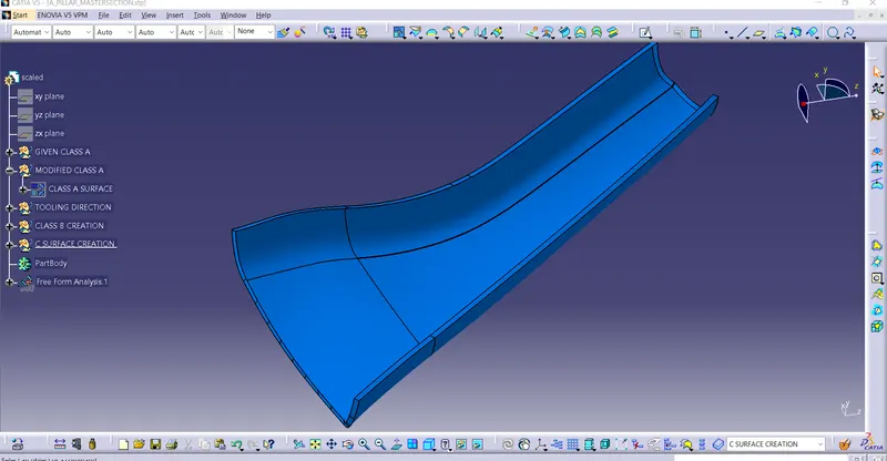
Once all surfaces are created, Class A, B and C surfaces are joined together to get the final closed volume. This closed volume is then converted into solid body using closed volume command in part design work bench.
- Draft analysis of final closed body
Draft analysis is done on final component to check manufacturing ability. The walls of the bin are having zero draft angle with tooling axis. This will be ignored since it is given in class A surface.
DOG HOUSE CREATION USING MASTER-SECTION
DOG HOUSE -
Dog house is an engineering feature used in plastic trim design. Dog houses are used as supporting feature. Sometimes other engineering features like snaps; locators etc. are mounded on them to increase their strength. Dog houses are subjected to draft analysis to prevent breakage of the component during ejection from mould cavity. Dog house and other engineering components are built on B-surface.
- IMPORTANT FUNCTION OF DOG HOUSE -
- Helps to avoid sink marks
- solves the length issues(ex: screw bosses can be formed at 100mm form B-surface)
- Always design houses perpendicular to the tooling axis
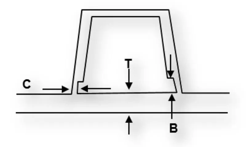
- "C" is where the doghouse contacts the backside of the surface
-
Doghouse wall thickness at the intersection of the part wall ( C ) should be 40% or less than the main wall stock ( T ).
-
Height of ( B ) should be between 3.0 – 6.0 mm
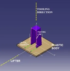
- CREATION OF PERPENDICULAR TOOLING AXIS FOR DOG HOUSE -
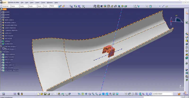
ISO-CONSTRAINED SKETCH -
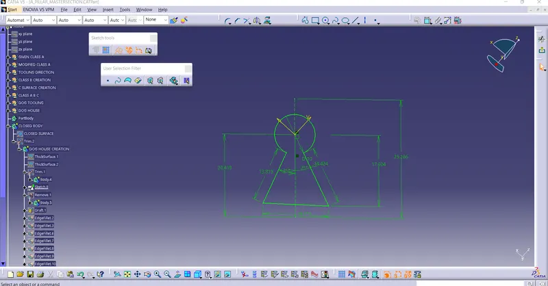
DOG HOUSE FOLLOWING MASTER-SECTION -
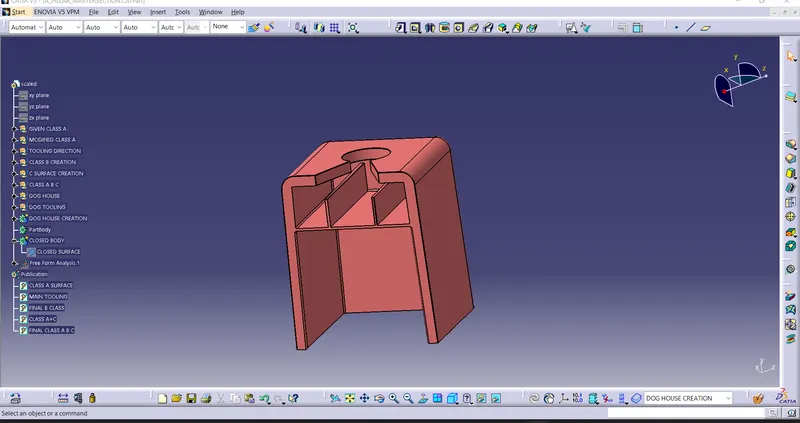
- DRAFT ANALYSIS ON DOG HOUSE -
-- For outside wall of dog house draft given is 1.5 degrees
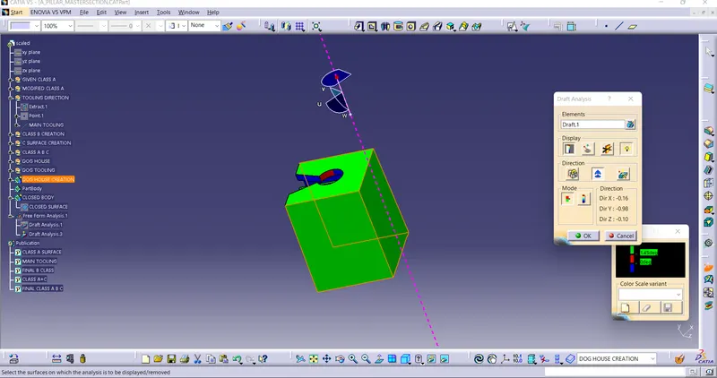
-- For inside wall of dog house draft given is 0.5 degrees
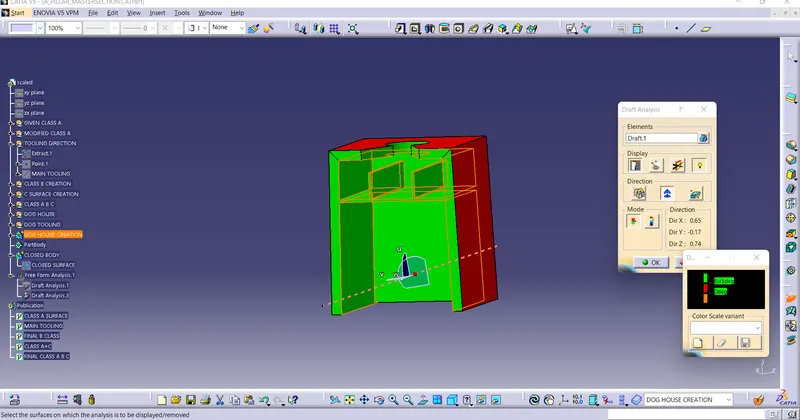
-- FINAL A PILLAR DESIGN WITH MASTER-SECTION -