Week 9 - Project_1 - Door Trim Lower with Engineering Features
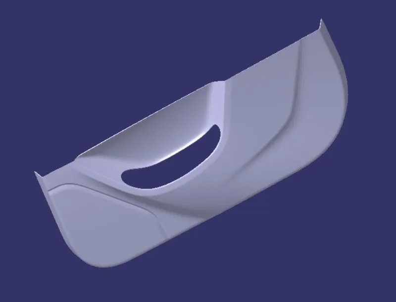
AIM :- To Create the Door Trim Lower Plastic component through the given Class-A surface. To begin with, the tooling axis for the given Class-A Surface should be created meeting the requirements of the draft angle and at the end perform the Draft analysis on the model. Also , create the Heat Stakes and the locators considering the design rules .
GIVEN :-
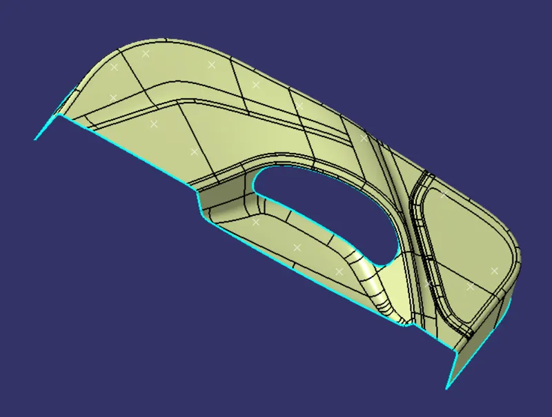
CLASS A SURFACE -
The A-surface or the styling surface is first checked for any gaps and other issues in its surfaces. This Surface acts as the input surface so any correction to be done should be with approval from the styling team or done by them. A- perfect surface is the one when a boundary is created, the lines are only on the edges of a component.
CREATION OF TOOLING AXIS -
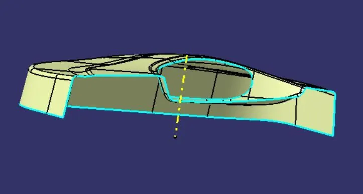
Tooling axis is the direction in which a core or cavity of mold opens. This Axis is very important to determine the orientation of the component in mold, core and cavity design.
The tooling axis is created by Bisecting line method. For that first I have drawn X and Z-direction clearing lines and then I draw bisecting line with the help of these two.
DRAFT ANALYSIS ON CLASS A SURFACE -
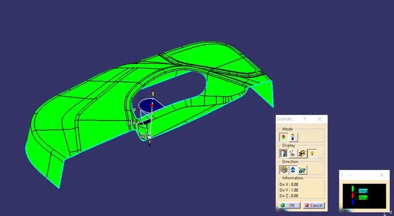
Draft analysis of the surface is carried to check if the surface or part can be manufactured with the required draft angle.
Draft angle is needed for the component to clear the core and cavity surface as it would have shrunk towards the center while cooling.
The draft angle in this design is 3 degrees. As A surface is a single surface there won't be much difference in color. The draft analysis of A-surface is shown below.
CREATION OF CLASS B SURFACE -
The A-surface is offsetted by 2.5 mm as it is the thickness required.
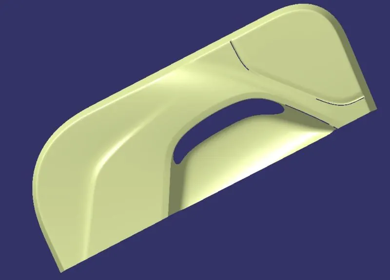
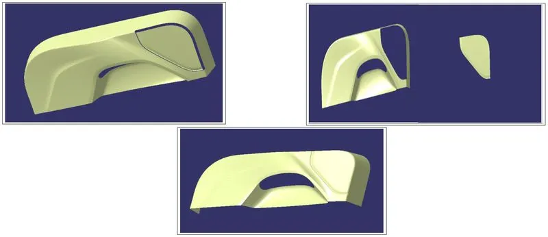
The offset surface is the B-surface but had some issues like in some areas shown in below images.
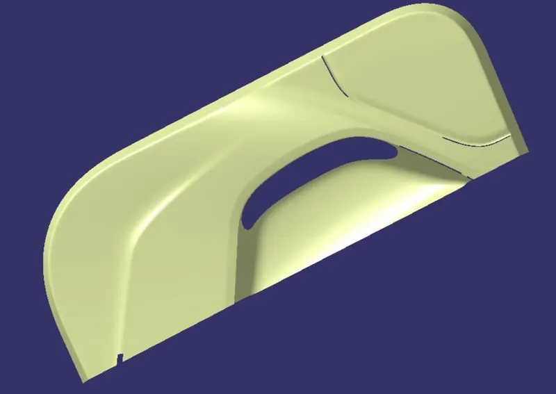
By using blend operation I close this missing surface. But for creating edge fillet I have follow proper procedure and gived edge fillet.
The following image shows the missing surfaces get closed.
Creation of edge fillet on class B -
First I have removed the edge fillet by using join operation and disambled above surface into two separate surfaces.
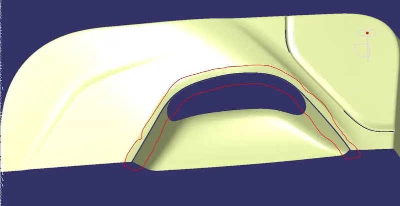
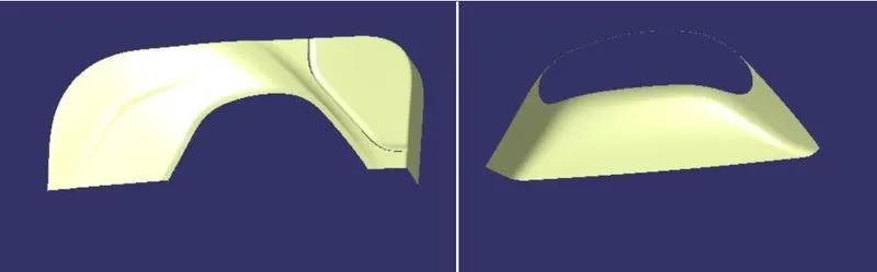
Then I have extrapolated joining boundary of these two surfaces and after trimming these two I have given edge fillet at joining.
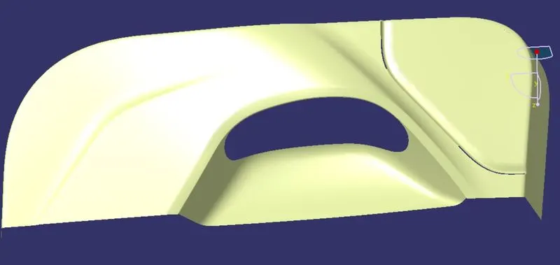
For second edge fillet I followed same procedure that shown in following image.
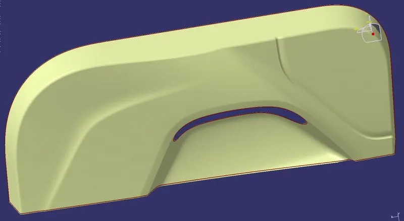
Then I have extrapolated outer boundary of Class B.
CREATION OF CLASS C SURFACE -
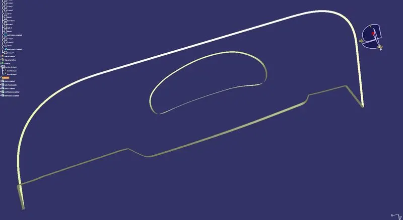
The A and B surfaces are connected by another single surface which is called the C surface.
It is created by using sweep with A surface acting as the reference surface and curve created from the boundary of the same surface.
Sweep with draft direction is also used to create A-surfaces.
CREATION OF CLOSE BODY -
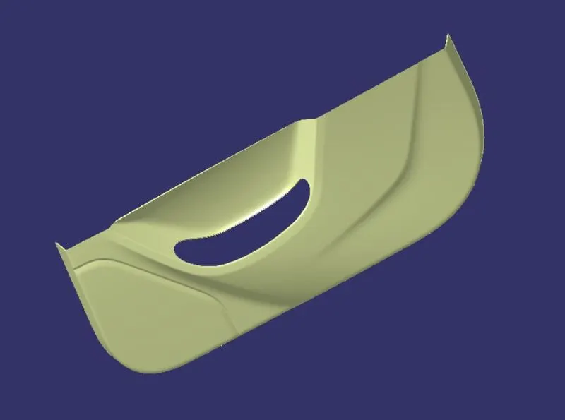
All the surfaces (A,B,C) are joined together to form a closed body.
CREATION OF SOLID BODY -
I used the Close Surface feature to make a solid body from the surface.
CREATION OF HEAT STAKES -
Heat staking also known as thermoplastic staking is the process of joining two dissimilar materials together. In heat staking we use local heating and cooling to raise the temperature of plastic components and allow plastic reforming to be carried out. This reforming can be used in a wide variety of applications.
Applications range from staking plastic bosses for assembly of car door panels to joining PCB’s to plastic housings. Benefits of this technique include; no vibration damage, no particulates, the ability to stake metalized coated applications and the capability to stake in difficult to access or restricted areas.
Advantages of Heat Staking
- Consistent, Fast & Economical Alternative to Rivets & Screws.
- Joins different materials Eg: Plastic to plastic , plastic to non-plastic or join 2 non-plastics.
- Able to handle difficult to weld plastics.
- Simple mechanism and accurate control.
Industry Applications
- Automotive : Reliable solution for interior parts, welding bumpers, tail light assemblies, dashboards & many more parts
- Textile : Creates durable seals without the need for glues, clips and yarns in product designs
- Appliances : Component welding for large or small household appliances
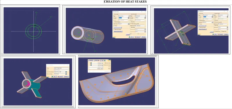
In following images I have shown how I created heat stakes.
First I have Create sketch for heat sketch on given point then that paded. Then for giving strength to heat stake I have create rib for support.Then I have given 0.5 degree draft to all surafces. Then I have transalated this heat stake to all other given point. And assembled all heat stakes in a single body and then trim it with main part body.
CREATION OF LOCATORS -
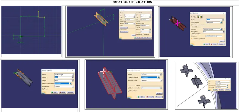
Locators are used to arrest the movement of component . Locators restrict the all movement like translational, rotational along all axes except translational movement along tooling direction for that we use heat stakes.
For creating locators I followed followimg steps that shown in below image.
DRAFT ANALYSIS ON FINAL COMPONENT -
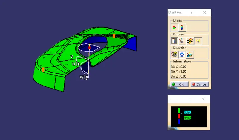
The final solid part body has to be analyzed using Draft analysis. This is done to check if all the areas of the body are satisfying the draft angle which is 3 degrees.
A draft angle is a taper applied to the vertical walls of the injection-molded component to assist with releasing the part from the mold.
Draft angles are a required feature of injection-molded custom parts. A functional part for injection molding has to have draft angles that face both the cavity and core sides. This will reduce the risk of damage to the parts and ensure that they can be ejected from the machine.