Week 9 - Project 1 - Door Trim Lower with Engineering Features
Design of Door Trim Lower with Engineering Features:
AIM: Create the Door Trim Lower Plastic component through the given Class-A surface.
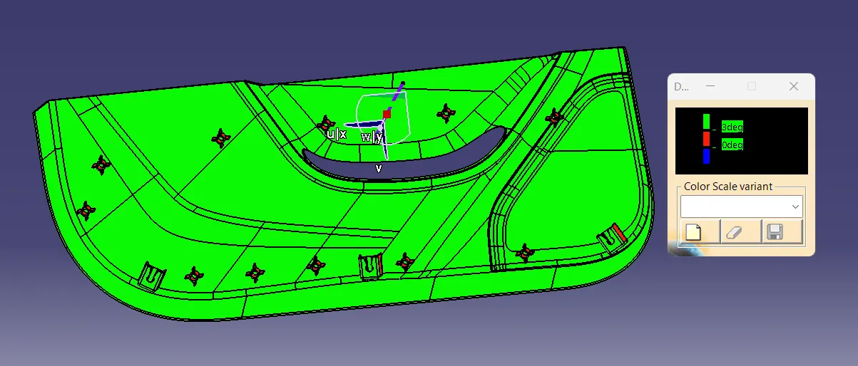
OBJECTIVE: To begin with, the tooling axis for the given Class-A Surface should be created meeting the requirements of the draft angle and at the end perform the Draft analysis on the model. Create the Heat Stakes and the locators considering the design rules mentioned in the video for the door applique.
KEY POINTS:
- Sketches
- Use Positioned sketch.
- Sketches should be Iso-Constrained.
- References
- Use the given points in the model to create the locators and Heat stakes.
- Refer to the below-given image for more details.
- Tree Structure
- Ensure Proper Tree Structure.
- Geometrical sets should have a proper name based on the sketches present inside of it.
- All the sketches should be created under the Geometrical set.
- Report
- A detailed report should be done explaining the draft analysis and the tooling axis creation.
- An explanation should be given on the way of creating the tooling axis, particularly the Bisecting method.
A Surface:
A Surface is the aethetic surface part of the model by using this as reference the other b surface and c surface is created.the aesthetic body part is part which should not go through any change in the aesthetic body itself.
Tooling axis :
Tooling axis is the the direction of tooing during manufacturing process it should be created by the means of flat surface in the direction same in y axis.
Draft analysis on the Class A Surface:
Draft report:
- Draft of 3 degree is given and the minimum draft can be given is 2.9 degree to clear all the curvatures.
- to provide aesthetic surface and the clear all undercuts draft is used in all automotive sectors.
- the draft is given over the tooling axis will give 3 degree of draft.
- the green colour shows the body is drafted fully over the surface.
Creation of B Surface :
It is the surface of offsetting A SURFACE to a minimum thickness of 2.5 mm. B Surface can be created by making some patches which are made by doing the offset.
CREATION C SURFACE:
- It is created at the edges of the given class A and Class B surface.
- from the A sURFACE given as referenced is used to create the c surface.
- and joing the C and A suface and trimming it with the b surface.
- making the closed body by using the thickening command.
img)point of view A and C surface join:
closed body:
creation of b side features:
- Heat stakes
- 4 way locators
- Dog house
HEAT STAKES creation:
sketching of hest stakes:-
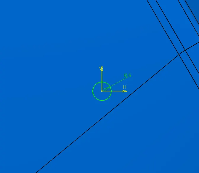
Pad is given as the thick ness of 1.5 mm:
adding ribs:
drafting of the heat stakes:
creation of 4 way locatrers:
sketching of 4 way locaters:
Padding the sketch :
drafting of 4 way locaters:
creation of dog house:
Sketching of dog house:
drafting of dog house:
drafting of closed body: